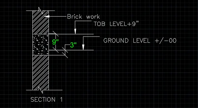
Creation of Column Schedule and Drawing Template using AutoCad
CREATION OF COLUMN SCHEDULE AND DRAWING TEMPLATE USING AUTOCAD
1.CREATING A COLUMN SCHEDULE
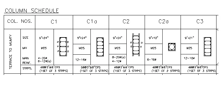
AIM-
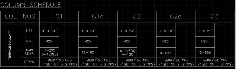
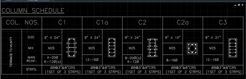
To create a column schedule as shown in the above figure in AutoCAD.
INTRODUCTION -
The column schedule is created using a AutoCAD software using many tools.The schedule is drafted with some procedure, so all the step by step procedure is mention below with diagrams and final result is given.
TOOLS USED-
- LINE
- TABLES
- TRIM
- DIMENSION
- OFFSET
- FILLET
PROCEDURE-
STEP 1
START AUTOCAD
- Go to START MENU, and select AutoCAD.
- The User Interface of AutoCAD is OPEN.
- Click the start Drawing tab
- The workspace of AutoCad is open,
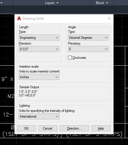
- Enter UNITS in the command box.
- Select ENGINEERING in TYPE, 0'-0.0" in PRECISION, and INCHES in UNITS TO SCALE INSERTED CONTENT.
- Select Angle type as DECIMAL DEGREE, and precision is 0 and direction are Anti-clockwise.
- Press OK.
STEP 2-
INSERT TABLE
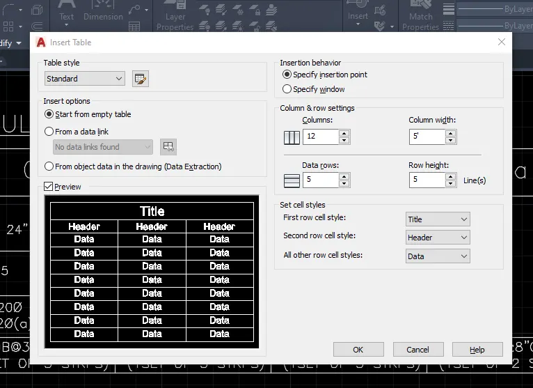
- Go to ANNOTATE > TABLE > INSERT TABLE
- Or type TABLE and press ENTER in the command line
- A dialog Box will Open
- Select a noumber of Column as 12 and column width as 5'
- Select a row as 5 and row height as 5
- Click OK.
- Now CLICK on screen , we get a table
- Now Select EXPLODE or type X and press ENTER to explod a table
- Select a TRIM command from the ribbion or Type TR and press ENTER.
- TRIM a unwanted line as per figure shown above.
STEP 3-
TEXT
- Select a single line text from HOME>TEXT>SINGL LINE
- Or type DTEXT and press ENTER.
- Specify a starting point of text
- Specify a text height as 8" and specify the rotation angle of text is 0
- Now write a text as COLUMN SCHEDULE
- Click on text and go to properties
- Select a font name as romans.shx
- click on ESC
- Agin type DTEXT and press ENTER.
- Specify a starting point of text
- Specify a text height as 8" and specify the rotation angle of text is 90
- Now write a text as TERRACE TO MUMTY'.
- Click on text and go to properties
- Select a font name as romans.shx
- click on ESC
- Agin type DTEXT and press ENTER.
- Specify a starting point of text
- Specify a text height as 8" and specify the rotation angle of text is 0
- Now write a text as COL. NOS.
- Click on text and go to properties
- Select a font name as romans.shx
- click on ESC
- Selecct a COPY or type CO and press ENTER.
- Select a COL. NOS. and make a copies
- then edit a text by command ED as C1,C1a and soo on..
- and press ESC.
STEP 4-
COLUMN DEATAILS
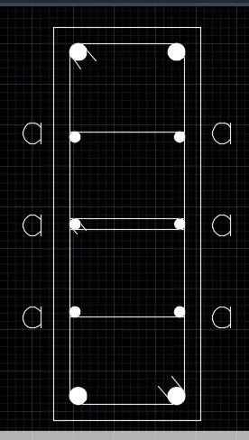
- select the Rectangle tool by entering RECTANGLE
- Specify the first point of the rectangle.
- Select Dimensions option in the command line.
- Specify length of rectangle as 9"
- Specify width of rectangle as 24"
- Select a OFFSET tool or type O and ENTER.
- Selecct a rectangle and specify a OFFSET distance as 1"
- Press ESC
- Select the Fillet tool, by entering 'F' in the command tab.
- Select the Radius option in the command line, and specify a radius as 0.5"
- Select a POLYLINE option in the command line
- Select the inner rectangle
- Press ESC
- Select a CIRCLE tool or type CO and ENTER.
- Specify radius as 0.5"(representing bars of 20 mm dia.).
- Select a CIRCLE tool or type CO and ENTER.
- and draw a circle of radius 0.3" (representing bars of 12 mm dia.).
- Select the circle of radius 0.5" and copy it to all desired locations do the same for the circle of radius 0.3"
- Draw lines to define the stirrups.
- Select a single line test or type DTEXT and press ENTER
- type the letter 'a' to highlight the bars of diameter 12 mm.
STEP 5
COLUMN DEATAILS
- select the Rectangle tool by entering RECTANGLE
- Specify the first point of the rectangle.
- Select Dimensions option in the command line.
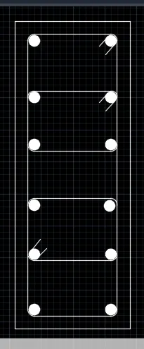
- Specify length of rectangle as 9"
- Specify width of rectangle as 24"
- Select a OFFSET tool or type O and ENTER.
- Selecct a rectangle and specify a OFFSET distance as 1"
- Press ESC
- Select the Fillet tool, by entering 'F' in the command tab.
- Select the Radius option in the command line, and specify a radius as 0.4"
- Select a POLYLINE option in the command line
- Select the inner rectangle
- Press ESC
- Select a CIRCLE tool or type CO and ENTER.
- Specify radius as 0.4"(representing bars of 16 mm dia.).
- Select the circle of radius 0.4" and copy it to all desired locations
- Draw lines to define the stirrups.
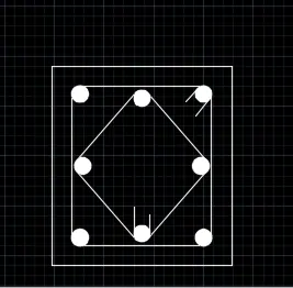
STEP 6
COLUMN DEATAILS
- select the Rectangle tool by entering RECTANGLE
- Specify the first point of the rectangle.
- Select Dimensions option in the command line.
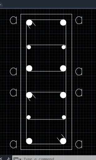
- Specify length of rectangle as 9"
- Specify width of rectangle as 24"
- Select a OFFSET tool or type O and ENTER.
- Selecct a rectangle and specify a OFFSET distance as 1"
- Press ESC
- Select the Fillet tool, by entering 'F' in the command tab.
- Select the Radius option in the command line, and specify a radius as 0.5"
- Select a POLYLINE option in the command line
- Select the inner rectangle
- Press ESC
- Select a CIRCLE tool or type CO and ENTER.
- Specify radius as 0.5"(representing bars of 20 mm dia.).
- Select a CIRCLE tool or type CO and ENTER.
- and draw a circle of radius 0.3" (representing bars of 12 mm dia.).
- Select the circle of radius 0.5" and copy it to all desired locations do the same for the circle of radius 0.3"
- Draw lines to define the stirrups.
- Select a single line test or type DTEXT and press ENTER
- type the letter 'a' to highlight the bars of diameter 20 mm.
STEP 7
COLUMN DEATAILS
- select the Rectangle tool by entering RECTANGLE
- Specify the first point of the rectangle.
- Select Dimensions option in the command line.
- Specify length of rectangle as 9"
- Specify width of rectangle as 10"
- Select a OFFSET tool or type O and ENTER.
- Selecct a rectangle and specify a OFFSET distance as 1"
- Press ESC
- Select the Fillet tool, by entering 'F' in the command tab.
- Select the Radius option in the command line, and specify a radius as 0.4"
- Select a POLYLINE option in the command line
- Select the inner rectangle
- Press ESC
- Select a CIRCLE tool or type CO and ENTER.
- Specify radius as 0.4"(representing bars of 16 mm dia.).
- Draw lines to define the stirrups.
STEP 8
COLUMN DEATAILS
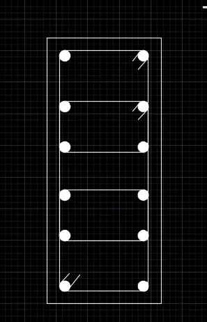
- select the Rectangle tool by entering RECTANGLE
- Specify the first point of the rectangle.
- Select Dimensions option in the command line.
- Specify length of rectangle as 9"
- Specify width of rectangle as 21"
- Select a OFFSET tool or type O and ENTER.
- Selecct a rectangle and specify a OFFSET distance as 1"
- Press ESC
- Select the Fillet tool, by entering 'F' in the command tab.
- Select the Radius option in the command line, and specify a radius as 0.4"
- Select a POLYLINE option in the command line
- Select the inner rectangle
- Press ESC
- Select a CIRCLE tool or type CO and ENTER.
- Specify radius as 0.4"(representing bars of 16 mm dia.).
STEP 9
- Place all column deatil in the table
- Enter 'CO' command in the command line.
- Select the coliumn sections created in steps 4, 5, 6, 7, 8.
- Copy the column sections to the Table cretaed in step 3.
- Press Esc.
RESULT -
2.CREATING A WINDOW SCHEDULE
AIM-
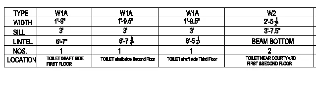
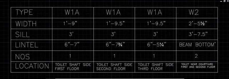
To create a window schedule as shown in above figure using AutoCAD.
INTRODUCTION -
The window schedule is draft using AutoCAD software using many tools. The plan is drafted with some procedure, so all step-by-step procedure mentionedntion below with diagrams and final result is given.
TOOLS USED-
- LINE
- TABLES
- TRIM
- DIMENSION
- OFFSET
- FILLET
PROCEDURE-
STEP 1
START AUTOCAD
- Go to START MENU, and select AutoCAD.
- The User Interface of AutoCAD is OPEN.
- Click the start Drawing tab
- The workspace of AutoCad is open,
- Enter UNITS in the command box.
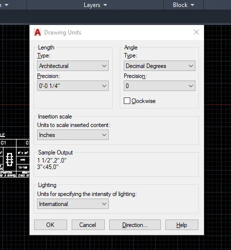
- Select ARCHITECTURAL in TYPE, 0'-0 1/4" in PRECISION, and INCHES in UNITS TO SCALE INSERTED CONTENT.
- Select Angle type as DECIMAL DEGREE, and precision is 0 and direction are Anti-clockwise.
- Press OK.
STEP 2
INSERT TABLE
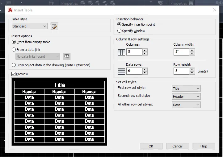
- Go to ANNOTATE > TABLE > INSERT TABLE
- Or type TABLE and press ENTER in the command line
- A dialog Box will Open
- Select a noumber of Column as 5 and column width as 5'
- Select a row as 6 and row height as 5
- Click OK.
- Now CLICK on screen , we get a table
- Now Select EXPLODE or type X and press ENTER to explod a table
- Select a TRIM command from the ribbion or Type TR and press ENTER.
- TRIM a unwanted line as per figure shown above.
STEP 3
TEXT
- Select a single line text from HOME>TEXT>SINGL LINE
- Or type DTEXT and press ENTER.
- Specify a starting point of text
- Specify a text height as 8" and specify the rotation angle of text is 0
- Now write a text as TYPE
- Click on text and go to properties
- Select a font name as romans.shx
- click on ESC
- Agin type DTEXT and press ENTER.
- Specify a starting point of text
- Specify a text height as 4" and specify the rotation angle of text is 0
- Now write a text as 1'9".
- Click on text and go to properties
- Select a font name as romans.shx
- click on ESC
- Agin type DTEXT and press ENTER.
- Specify a starting point of text
- Specify a text height as 2" and specify the rotation angle of text is 0
- Now write a text as TOILET SHAFT.
- Click on text and go to properties
- Select a font name as romans.shx
- click on ESC
RESULT-
3.CREATING A DRAWING TEMPLATE

AIM-
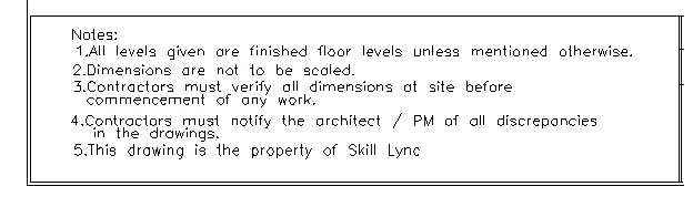
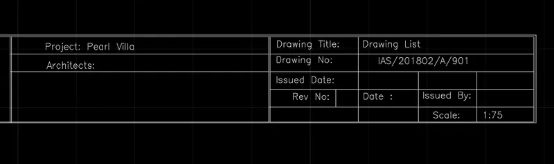
To create a drawing template as shown in above figure using AutoCAD.
INTRODUCTION -
The a drawing template is draft using a AutoCAD software using many tools.The plan is drafted with some procedure, so all the step by step procedure is mention below with diagrams and final result is given.
TOOLS USED-
- LINE
- TABLES
- TRIM
- DIMENSION
- OFFSET
- FILLET
PROCEDUR -
STEP 1
START AUTOCAD
- Go to START MENU, and select AutoCAD.
- The User Interface of AutoCAD is OPEN.
- Click the start Drawing tab
- The workspace of AutoCad is open,
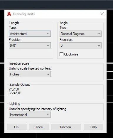
- Enter UNITS in the command box.
- Select ARCHITECTURAL in TYPE, 0'-0 " in PRECISION, and INCHES in UNITS TO SCALE INSERTED CONTENT.
- Select Angle type as DECIMAL DEGREE, and precision is 0 and direction are Anti-clockwise.
- Press OK.
STEP 2
INSERT TABLE
- Go to ANNOTATE > TABLE > INSERT TABLE
- Or type TABLE and press ENTER in the command line
- A dialog Box will Open
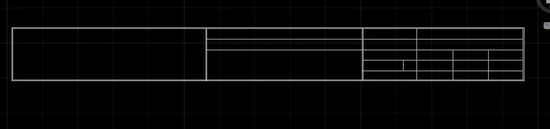
- Select a noumber of Column as 6 and column width as 5'
- Select a row as 5 and row height as 5
- Click OK.
- Now CLICK on screen , we get a table
- Now Select EXPLODE or type X and press ENTER to explod a table
- Select a TRIM command from the ribbion or Type TR and press ENTER.
- TRIM a unwanted line as per figure shown above.
STEP 3
TEXT
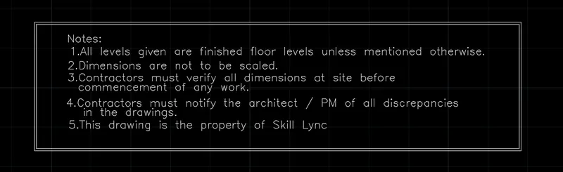
- Select a Multi line text from HOME>TEXT>MULTILINE TEXT
- Or type MTEXT and press ENTER.
- Specify a starting point of text
- Specify a text height as 10"
- Now write a text as TYPE
- Click on text and go to properties
- Select a font name as romans.shx
- click on ESC
RESULT-

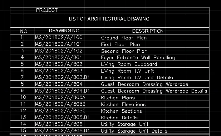
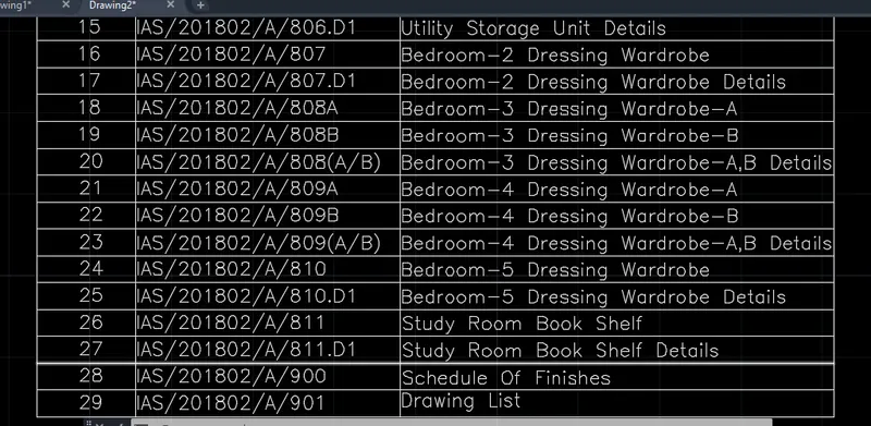
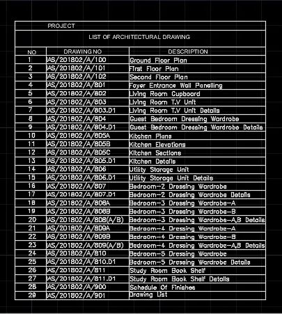
4.CREATING A LIST OF DRAWING SCHEDULE
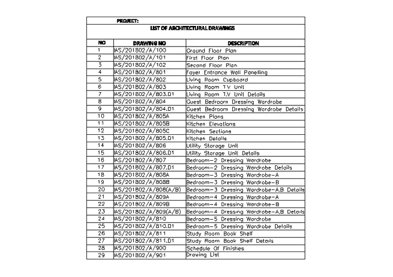
AIM-
To Create a list of drawing schedule as shown in above figure using AutoCAD.
INTRODUCTION -
The list of drawing schedule is draft using a AutoCAD software using many tools.The plan is drafted with some procedure, so all the step by step procedure is mention below with diagrams and final result is given.
TOOLS USED-
- LINE
- TABLES
- TRIM
- DIMENSION
- OFFSET
- FILLET
PROCEDUR -
STEP 1
START AUTOCAD
- Go to START MENU, and select AutoCAD.
- The User Interface of AutoCAD is OPEN.
- Click the start Drawing tab
- The workspace of AutoCad is open,
- Enter UNITS in the command box.
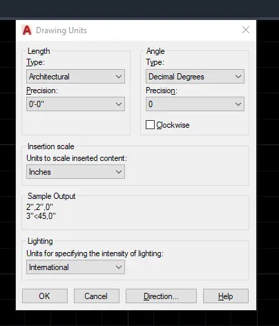
- Select ARCHITECTURAL in TYPE, 0'-0 " in PRECISION, and INCHES in UNITS TO SCALE INSERTED CONTENT.
- Select Angle type as DECIMAL DEGREE, and precision is 0 and direction are Anti-clockwise.
- Press OK.
STEP 2
INSERT TABLE
- Go to ANNOTATE > TABLE > INSERT TABLE
- Or type TABLE and press ENTER in the command line
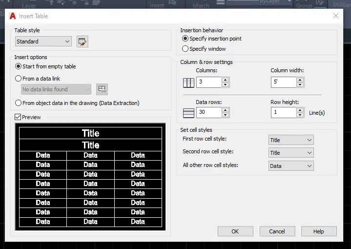
- A dialog Box will Open
- Select a noumber of Column as 3 and column width as 5'
- Select a row as 30 and row height as 1
- Click OK.
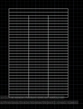
- Now CLICK on screen , we get a table
- Now Select EXPLODE or type X and press ENTER to explod a table
- Select a TRIM command from the ribbion or Type TR and press ENTER.
- TRIM a unwanted line as per figure shown above.
STEP 3
TEXT
- Select a Multi line text from HOME>TEXT>MULTILINE TEXT
- Or type MTEXT and press ENTER.
- Specify a starting point of text
- Specify a text height as 10"
- Now write a text as TYPE
- Click on text and go to properties
- Select a font name as romans.shx
- click on ESC
RESULT -
5.CREATING THE BEAM DEATIL.
AIM-
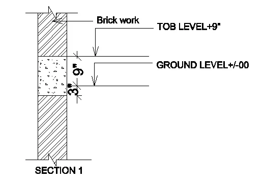
To Create a beam deatil as shown in above figure using AutoCAD.
INTRODUCTION -
The beam deatail is draft using AutoCAD software using many tools.The plan is drafted with some procedure, so all the step by step procedure is mention below with diagrams and final result is given.
TOOLS USED-
- LINE
- TABLES
- TRIM
- DIMENSION
- OFFSET
PROCEDUR -
STEP 1
START AUTOCAD
- Go to START MENU, and select AutoCAD.
- The User Interface of AutoCAD is OPEN.
- Click the start Drawing tab
- The workspace of AutoCad is open,
- Enter UNITS in the command box.
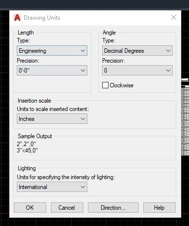
- Select ENGINEERING in TYPE, 0'-0" in PRECISION, and INCHES in UNITS TO SCALE INSERTED CONTENT.
- Select Angle type as DECIMAL DEGREE, and precision is 0 and direction are Anti-clockwise.
- Press OK.
STEP 2
- Slect a LINE tool from ribbion or type L and press ENTER.
- Specify the first point as 10,10 in the command line.
- Specify the coordinate of next point as @0',4' in the command line.
- Specify the coordinate of next point as @9",0' in the command line.
- Specify the coordinate of next point as @0',-4' in the command line.
- Click ‘Close’ on the command line.
- Slect a OFFSET tool from ribbion or type O and press ENTER.
- Enter 1' as offset distance in the command line.
- Select the top horizontal line of the above drawing.
- Specify the point on the downward side of the line to offset.
- Extend the offsetted line.
- Repeat Offset again, select the last offsetted line, specify a distance of 9", and click downwards.
- Repeat offset again, select the last offsetted line, specify a distance of 3", and click downwards.
- Press Esc.
- Slect a LINE tool from ribbion or type L and press ENTER.
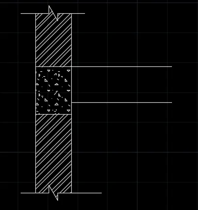
- Draw lines to represent the cut edges of the wall section.
- Press 'Esc' to cancel the Line tool.
- Select the Trim tool from the Ribbon, and trim the unwanted lines.
- Press Esc.
- Enter 'H' in the command line.
- Select STEEL Pattern, and click on the UPPER AND BELOW .
- Next select the AR-CONC Pattern and click inside the mid section.
STEP 3
- Open a dimension-style dialog box by pressing DIMSTY in the command line.
- Click on the Modify tab.
- Now go to the text and change the text heightand color as per Requirement.
- Here, I used a 3"unit for a text height
- Open a dimension-style dialog box by pressing DIMSTY in the command line.
- Click on the Modify tab.
- Now go to the text and change the arrow size and color as per Requirement.
- Here, I used a 3" ARROW SIZE
- Give the all dimension for the drawing as shown in fig.
- For liner dimension, Enter DIMLIN
- For angular dimension,Enter DIMANG
- And for diameter, Enter DIMDIA
RESULT