Creation of Column Schedule and Drawing Template using AutoCad
1.Column schedule:
Aim:
To create column schedule using Auto CAD.
Introduction:
The following commands and tools are used in this Auto CAD drawing,
- Line: It helps to create a line between two points
- Rectangle: It helps to create a four-sided geometry with a desired length and width.
- Offset: It helps to offset an object at a particular distance.
- Move: It helps to move an already existing object from one point to the other by picking a base point.
- Copy: It helps to copy an already existing object from one point to the other by picking a base point.
- Trim: It helps to trim off the extra lines or objects of a selected object which is created while using other tools.
- Break at point: It helps to break the selected object at a single point
- Erase: It helps to erase a selected object.
- Hatch: It helps to hatch a select closed objects in different patterns
- DT: single text: It helps to enter the single line text
- MT: Multi-line text: It helps to type multi line text or paragraphs
- Text edit: It helps to edit the typed texted.
Note:
- Keep Ortho on and Object snap on which are in the status bar throughout the drawing which helps to find midpoint, center point and so on.
Procedure:
- In command: units
- The drawing units dialog box appears, in that select Engineering as type and precision as 0’0.0”, intersection scale as inches and click OK.
- In command: limits
- Specify lower left corner: 0’0.0”,0’0.0”
- Specify upper right corner: 100’,100’
- Enter zoom and enter all in the command.
- Select line command and pick up a random point and move cursor to 0 angle and type 12’ and move to 90 degree and enter 5’ and move cursor to 180 and type 12’ and click close.
- Select offset and give offset distance as 1’ and select the left vertical line and move cursor to 0 degree and create 11 offset lines.
- Select the bottom horizontal line and create 4 offset lines horizontally.
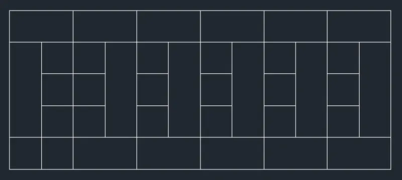
- Select Trim command and select the object as a whole and trim the lines which are not included in the table like shown below.
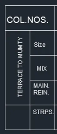
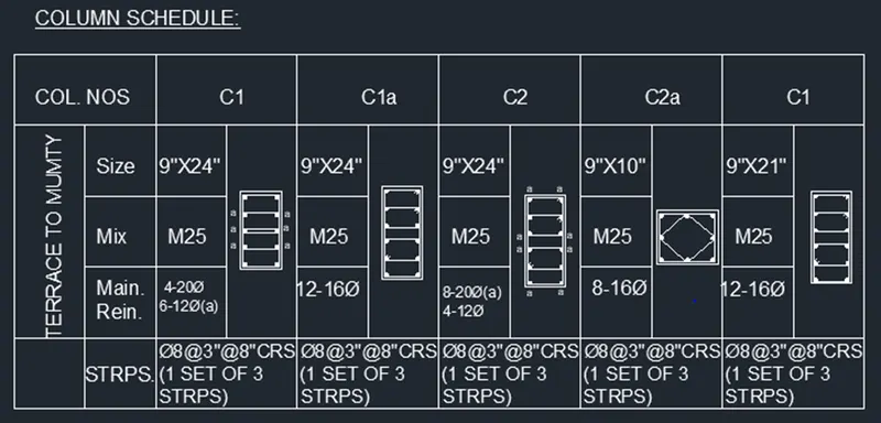
- In command enter DT and specify the starting point inside the top first row first column and give text height as 3” and angle as 0. And type COL.NOS and again click to the follow up column and type as follow

- Enter DT and specify starting point inside the second-row long column and give text height as 2” and give angle as 90 and enter TERRACE TO MUMTY.
- Click Inside second- row second- column and give text height as 2” and text angle as 0 and enter SIZE and click next following row in the same column and type as follow
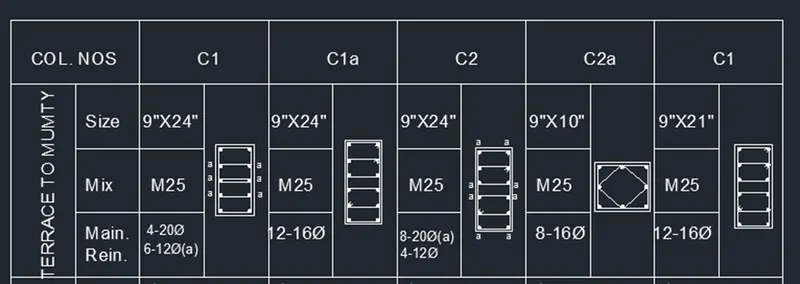
- Enter DT and specify starting point inside the first row first column under the C1 and give text angle as 0 and type 9”x24” and click the next row and type M25
- Select copy and select 9”x24” and M25 as the object and click a base point and copy it to first column under C1a, C2, C2a AND C3 respectively.
- Double click the C2a and C3 size for text edit and type 9”X10” and 9”x21” respectively
- Enter MT and click starting and end point inside the C1 first column third row and give text height as 1.5” and text style as Romans and enter 4-20Ø, 6-12Ø(a).
- For Ø go to symbol and select diameter.
- Continue the same procedure for C1a, C2,C2a,C3 and type 12-16Ø ,8-20Ø (a) 4-12Ø ,8-16Ø ,12-16Ø respectively
- Select rec command and draw random size 4 rectangles and a square and create offset of it.
- Select line command and pick mid-point of each rectangle and draw a horizontal line and again pick mid-point at the half of the rectangle and draw a horizontal line on both side for the all four rectangles.
- Select circle command and create small random circle at intersection point to create like rod.
- For Square like cross sectional column select circle command and create small random circle and place it at the four corners and two mid-point
- Select line command and pick tangent point and join circles in the midpoint.
- Enter H and select all the circles and Select pattern as SOLID and click inside the circle
- To above-mentioned cross-sectional columns are shown below
- Enter MT and click the starting and end point inside the C1 last row and select text height as 2” and text font as Romans and type Ø8@3”&8”CRS(1 SET OF 3 STRPS.)
- Select copy command and select the above text and click a base point and copy it in the last row of the C1a, C2, C2a and C1 respectively.
- Select MT and click pick a starting and end point in the top left above the table and select underline option and give text height as 3” and type COLUMN SCHEDULE
Result:
The following result is obtained by the above-mentioned steps.
2.Window schedule:
Aim:
To create window schedule using Auto CAD.
Introduction:
The following commands and tools are used in this Auto CAD drawing,
- Line: It helps to create a line between two points
- Rectangle: It helps to create a four-sided geometry with a desired length and width.
- Offset: It helps to offset an object at a particular distance.
- Move: It helps to move an already existing object from one point to the other by picking a base point.
- Copy: It helps to copy an already existing object from one point to the other by picking a base point.
- Trim: It helps to trim off the extra lines or objects of a selected object which is created while using other tools.
- Break at point: It helps to break the selected object at a single point
- Erase: It helps to erase a selected object.
- DT: single text: It helps to enter the single line text
- MT: Multi-line text: It helps to type multi line text or paragraphs
- Text edit: It helps to edit the typed texted.
Note:
- Keep Ortho on and Object snap on which are in the status bar throughout the drawing which helps to find midpoint, center point and so on.
Procedure:
- In command: units
- The drawing units dialog box appears, in that select Engineering as type and precision as 0’0.0”, intersection scale as inches and click OK.
- In command: limits
- Specify lower left corner: 0’0.0”,0’0.0”
- Specify upper right corner: 100’,100’
- Enter zoom and enter all in the command.
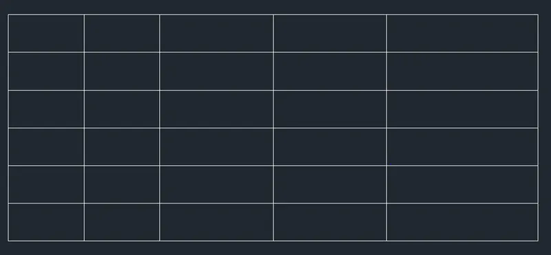
- Select line command and pick up a random point and move cursor to 0 angle and type 14” and move to 90 degree and enter 6” and move cursor to 180 and type 14” and click close.
- Select offset and give offset distance as 1’ and select the bottom line and move cursor to 90 degree and create 5 offset lines.
- Select the left vertical line and give offset distance as 2” create 2 offset lines and give offset distance as 3” and move cursor to the 0 degree and create 2 offset lines
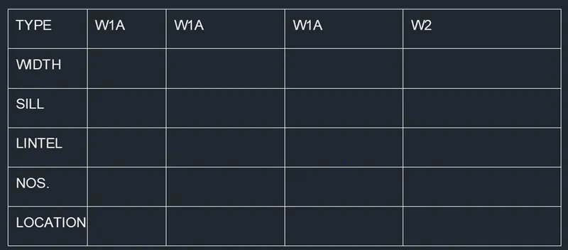
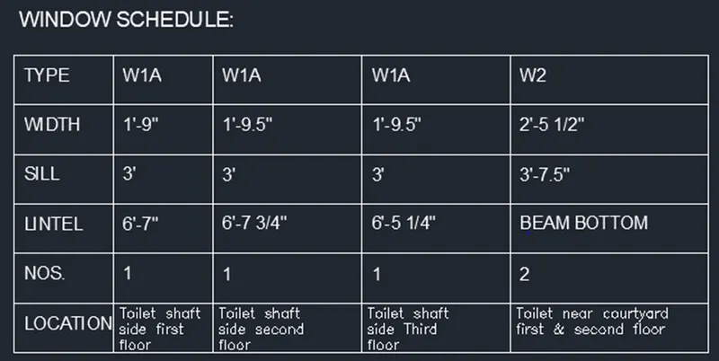
- In command enter DT and specify the starting point inside the top first row first column and give text height as 0.25” and angle as 0. And enter TYPE and again click to the follow up column and type WIDTH, SILL, LINTEL, NOS., LOCATION.
- With same setting click the first row, second column and type W1A, W1A, W1A, W2 in the next three columns respectively.
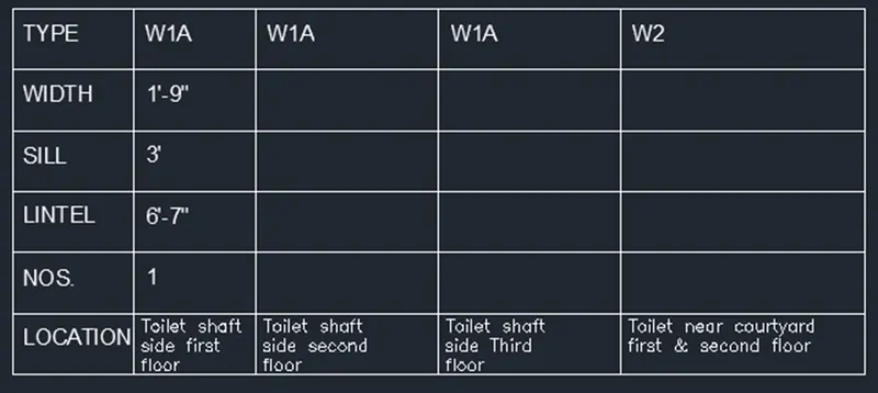
- Then click the second column second row and type 1’-9” and click inside next row in the same column and type3” and in the next two row of the same column type 6’-7” and 1 respectively
- In the same column last row enter MT and click starting and end point and give text height as 0.19” and font as Romans and type Toilet shaft side first floor.
- Select copy tool and select the above text and pick a base point and copy it in the other three columns in the same row
- Double click the copied text for text edit and type Toilet shaft side second floor, Toilet shaft side third floor and Toilet near courtyard first & second floor in the respective columns one by one as follow
- Enter DT and click the starting point inside the third column second row and give text height as 0.25” and type 1’-9.5” and click inside the next three rows and type 3’, 6’-7 3/4” and 1 respectively.
- Click inside the second row fourth column and type 1’-9.5” and inside the next three rows and type 3’, 6’-5 1/4” and 1 respectively.
- Click inside the second row fifth column and type 2’-5 1/2” and inside the next three rows and type 3’-7.5”, BEAM BOTTOM and 2 respectively.
- Select DT and Click the top left above the table and give text height as 0.3” and angle as 0. And enter WINDOW SCHEDULE:
Result:
- The following result is obtained by the above-mentioned steps.
3.Drawing template:
Aim:
To create drawing schedule using Auto CAD.
Introduction:
The following commands and tools are used in this Auto CAD drawing,
- Line: It helps to create a line between two points
- Rectangle: It helps to create a four-sided geometry with a desired length and width.
- Offset: It helps to offset an object at a particular distance.
- Move: It helps to move an already existing object from one point to the other by picking a base point.
- Copy: It helps to copy an already existing object from one point to the other by picking a base point.
- Trim: It helps to trim off the extra lines or objects of a selected object which is created while using other tools.
- Break at point: It helps to break the selected object at a single point
- Erase: It helps to erase a selected object.
- DT: single text: It helps to enter the single line text
- MT: Multi-line text: It helps to type multi line text or paragraphs
- Text edit: It helps to edit the typed texted.
Note:
- Keep Ortho on and Object snap on which are in the status bar throughout the drawing which helps to find midpoint, center point and so on.
Procedure:
- In command: units
- The drawing units dialog box appears, in that select Engineering as type and precision as 0’0.0”, intersection scale as inches and click OK.
- In command: limits
- Specify lower left corner: 0’0.0”,0’0.0”
- Specify upper right corner: 100’,100’
- Enter zoom and enter all in the command.
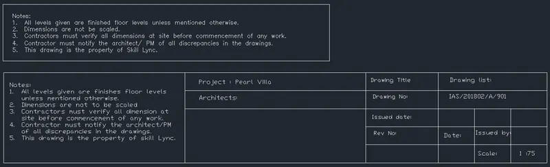
- Select rectangle command and pick a random point as start point and create the rough long rectangle.
- Enter MT and click a point inside the rectangle as a starting point and also click the end point near the end of the length of the rectangle by moving the cursor to the right.
- Give the text height as 0.2” and font as Romans
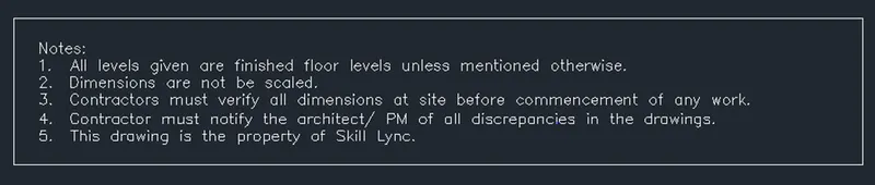
- Enter the following notes as follows below.
- Select rectangle command and pick s point below the above notes and give dimension, length as 10”and width as 5” and click.
- Select copy command and copy the above rectangle and pick a base point and copy it two times by touching the width of the rectangle.
- Enter MT and click a point inside the first rectangle as a starting point and also click the end point near the end of the length of the first rectangle by moving the cursor to the right and type the text as follow

- Select Break at a point command and select the second rectangle as object and click the top and right corners of the rectangle to form to separate lines and using same procedure break the third rectangle top length in to line
- Select offset and select the top length of the second rectangle and give offset distance as 1” and create two offset lines.
- Select the third rectangle length as object and create five offset lines
- Select the second rectangle width as object and create three offset line by giving offset distance as 4”, 1”,2” one by one
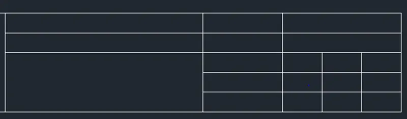
- Select Trim command and select the object as a whole and trim the excess lines in the third rectangular to for the following table.
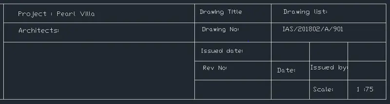
- Select DT command and give text height as 0.2” and click inside the first row of the second rectangle and type Project: Pearl villa
- Then move the cursor and click the next boxes to type the notes as follow
-
Result:
- The following result is obtained by the above-mentioned steps.
4.The list of drawing schedule:
Aim:
To create the list of drawing schedule using Auto CAD.
Introduction:
The following commands and tools are used in this Auto CAD drawing,
- Line: It helps to create a line between two points
- Rectangle: It helps to create a four-sided geometry with a desired length and width.
- Offset: It helps to offset an object at a particular distance.
- Move: It helps to move an already existing object from one point to the other by picking a base point.
- Copy: It helps to copy an already existing object from one point to the other by picking a base point.
- Trim: It helps to trim off the extra lines or objects of a selected object which is created while using other tools.
- Break at point: It helps to break the selected object at a single point
- Erase: It helps to erase a selected object.
- DT: single text: It helps to enter the single line text
- MT: Multi-line text: It helps to type multi line text or paragraphs
- Text edit: It helps to edit the typed texted.
Note:
- Keep Ortho on and Object snap on which are in the status bar throughout the drawing which helps to find midpoint, center point and so on.
Procedure:
- In command: units
- The drawing units dialog box appears, in that select Engineering as type and precision as 0’0.0”, intersection scale as inches and click OK.
- In command: limits
- Specify lower left corner: 0’0.0”,0’0.0”
- Specify upper right corner: 100’,100’
- Enter zoom and enter all in the command.
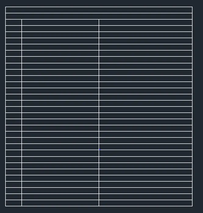
- Select line command and pick up a random point and move cursor to 0 angle and type 30” and move to 90 degree and enter 32” and move cursor to 180 and type 30” and click close.
- Select offset and give offset distance as 1’ and select the bottom line and move cursor to 90 degree and create 31 offset lines.
- Select the left vertical line and give offset distance as 2” create1 offset line and give offset distance as 12” and move cursor to the 0 degree and create 1 offset line.
- Select Trim command and trim the first two row’s vertical lines inside the table as shown below.
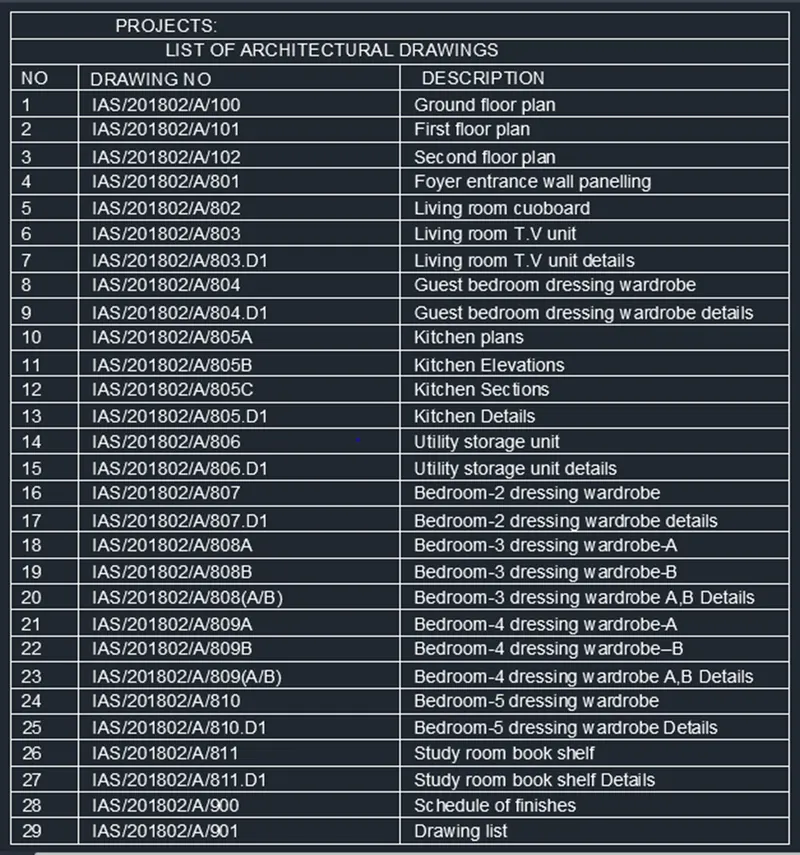
- In command enter DT and specify the starting point inside the top first row and give text height as 0.5” and angle as 0. And enter PROJECTS and again click to the next row and type LIST OF ARCHITECTURAL DRAWINGS
- Click the third row first column and type NOS. and in the same column follow up rows type numbers from 1 to 29 one by one.
- Click the third row second column and type as DRAWING NOS. and in the same row next column type as DESCRIPTION
- Click the row under DRAWING NOS and type as IAS/201802/A/100, etc., also and under DESCRIPTION type as Ground floor plan, first floor plan, etc., respectively as shown in the result.
Result:
- The following result is obtained by the above-mentioned steps.
5.The beam details with text:
Aim:
To create the beam details with text using Auto CAD.
Introduction:
The following commands and tools are used in this Auto CAD drawing,
- Line: It helps to create a line between two points
- Rectangle: It helps to create a four-sided geometry with a desired length and width.
- Offset: It helps to offset an object at a particular distance.
- Move: It helps to move an already existing object from one point to the other by picking a base point.
- Copy: It helps to copy an already existing object from one point to the other by picking a base point.
- Trim: It helps to trim off the extra lines or objects of a selected object which is created while using other tools.
- Mirror: It helps to mirror image the selected object on the other side.
- Break at point: It helps to break the selected object at a single point
- Erase: It helps to erase a selected object.
- Hatch: It helps to hatch a select closed objects in different patterns
- DT: single text: It helps to enter the single line text
- MT: Multi-line text: It helps to type multi line text or paragraphs
- Text edit: It helps to edit the typed texted.
Note:
- Keep Ortho on and Object snap on which are in the status bar throughout the drawing which helps to find midpoint, center point and so on.
Procedure:
- In command: units
- The drawing units dialog box appears, in that select Engineering as type and precision as 0’0.0”, intersection scale as inches and click OK.
- In command: limits
- Specify lower left corner: 0’0.0”,0’0.0”
- Specify upper right corner: 100’,100’
- Enter zoom and enter all in the command.
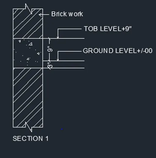
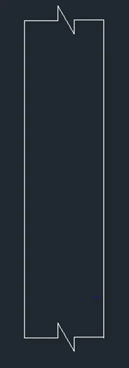
- Select line command and pick a point and move cursor to the 270 degree and enter 4’ to draw a line.
- Select offset and give offset distance as 1’ and select the above drawn line and create a single offset line.
- Select line command and pick the bottom point of the first vertical line and draw a line, zig-zag line and a line by touching the other end of the line.
- Select mirror command and select the object which is created and pick a center point and create a mirror image of the object
- Select line command and pick the first point as the bottom line of the left vertical line and move cursor up and give distance as 2’ and move cursor to the left click and join the other end of the line
- Select offset and select the previously drawn horizontal line and give offset distance as 1’ and create an offset line
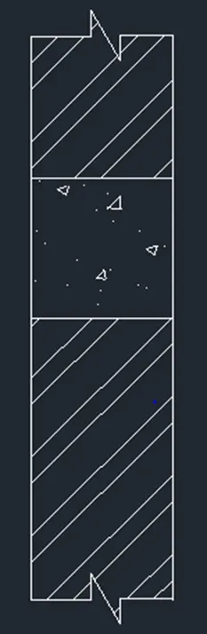
- Enter H and select the pattern as ANSI32 and scale as 0.05 and pick internal point as the bottom 2’ segment and click it and move cursor and click the top 1’ segment to form the same hatch.
- With the same procedure change the hatch pattern to AR CONC and pick the internal point inside the middle segment to form hatch as shown below
- Select line command and extend the second horizontal line outside with random distance.
- Select offset and pick the previous drawn line as object and give offset distance as 3” and again give offset distance as 9” and create another offset line.
- Enter DT and select a point between the bottom offset line which created previously and give text height as 2” and rotation as 90 degree and type 3”
- Click a point between top offset lines and with same setting type 9”
- Pick a point away from the offset lines and near 3” text and give rotation as 0 and enter GROUND LEVEL+/-00
- Now pick a point near 9” text and with above setting type TOB LEVEL+9”
- Again, click a point near the top segment and type Brick work like shown belo
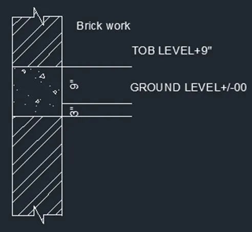
- Click the point under the drawing and type SECTION 1
- Select line command and form arrow lines to pinpoint the text to the respective objects.
Result:
- The following result is obtained by the above-mentioned steps.