Creation of Column Schedule and Drawing Template using AutoCad
1
AIM:
Sketch of the table of the column schedule
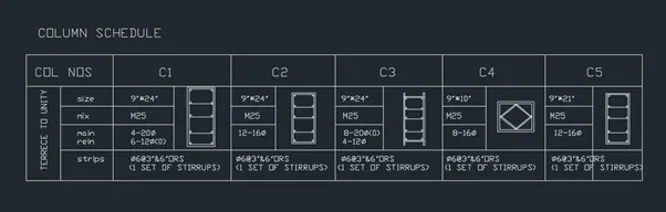
- In command prompt type (startup:1)
- Then file>new
- Then create new drawing window select metric in default settings
- In advanced setup in units check on the architectural, angle in degrees, then ok
- In command prompt type (xl enter h enter v) construction line horizontal and vertical respectively is obtained
- Next, in command prompt type(mtext) and write the texts by leaving the spaces for the diagrams and complete all the small sized text that was to written and enter
- Select the craeted horizontal construction line and copy to the desired positions
- Similarlly, Select the craeted vertical construction line and copy to the desired positions
- In command prompt type (tr enter) select all the lines and trim off all the unwanted lines and form the desired sha[pe of the table
- For the heading use DTEXT and type at the required points
- Similarly type dtext and rotate the ‘terrace of unity text’ for 90 degrees
- Draw all the diagrams with help of the line and circle commands and
- Scale the m to required sizes and move them to their respective positions
Result:
Table of the column schedule was obtained
2
AIM:
Sketch of the table of reqired fields
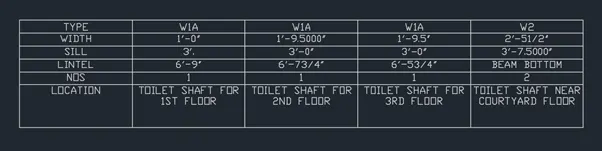
- In command prompt type (startup:1)
- Then file>new
- Then create new drawing window select metric in default settings
- In advanced setup in units check on the architectural, angle in degrees, then ok
- In the annotation folder select the table and create the table of the desired number of the rows and columns as we can also see the preview as shown in the figure below
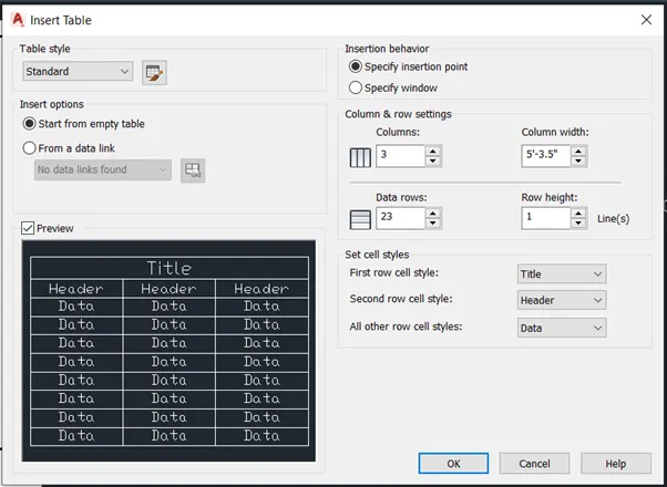
- Here, also we can specify the row and column width in the above table.
- Fill all the rows and columns with the required data and justify the position of the text in the cells
- We can delete the extra cells if any of them are not required.
Result:
Required table was sketched in the AutoCAD
3
Aim:
How to write the text in the AutoCAD
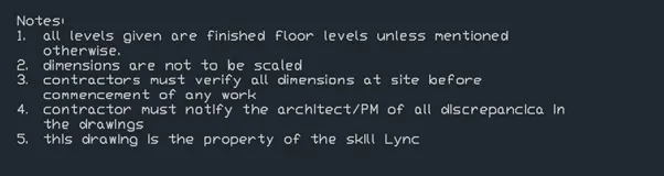
- In command prompt type (startup:1)
- Then file>new
- Then create new drawing window select metric in default settings
- In advanced setup in units check on the architectural, angle in degrees, then ok
- In command prompt type (mtext)
- Where multi line text will be popped and writes notes
- Then switch on the bulletins and numbering in the text editor and type all the text
- And by typing dims in the command prompt we can change or modify the size of the text and save
Result:
Required notes were written.
4
AIM:
Sketch of the table of reqired fields
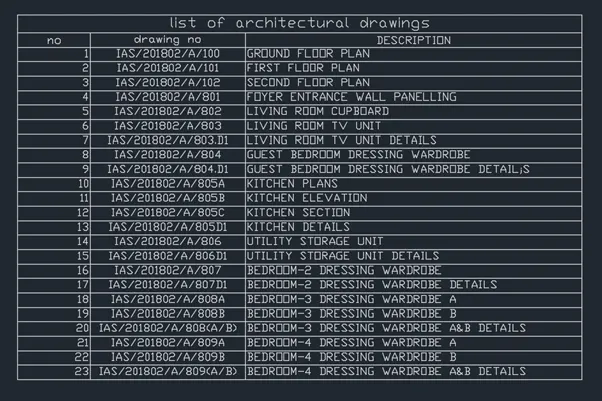
- In command prompt type (startup:1)
- Then file>new
- Then create new drawing window select metric in default settings
- In advanced setup in units check on the architectural, angle in degrees, then ok
- In the annotation folder select the table and create the table of the desired number of the rows and columns as we can also see the preview as shown in the figure below
- Here, also we can specify the row and column width in the above table.
- Fill all the rows and columns with the required data and justify the position of the text in the cells
- We can delete the extra cells if any of them are not required.
- Select the required fields to justify and justify them to required positions.
Result:
Required table was sketched in the AutoCAD
5
Aim:
Sketch the Section of the beam the specification was provided
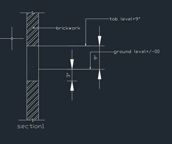
- In command prompt type (startup:1)
- Then file>new
- Then create new drawing window select metric in default settings
- In advanced setup in units check on the architectural, angle in degrees, then ok
- In command prompt type (xl enter v) construction line horizontal and vertical respectively is obtained
- Offset the vertical line for required width of the beam and
- Use line to trim the section for required measurements
- In command prompt type(h) and hatch the area required and by selecting teem resize it to the required scale in the properties tab
- By the detext section 1 was written
- By selecting the leader tool indicate the brick work and the ground and top level
- With the linear dimension tool measure the both dimensions and display them
- And by typing dims in the command prompt, we can change or modify the size of the text and save
- By selecting the leader, we can change the landing distance of the text in the leader
Result
Given beam section was sketched.