Creation of Column Schedule and Drawing Template using AutoCad
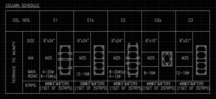
1) COLUMN SCHEDULE
AIM:
To create the column schelude using autocad
INTRODUCTION:
The column schelude using autocad is created by lines and circles. the procedure and result should be written after creating yhe column schelude
PROCEDURE:
STEP1:
- open the autocad softwareand click start drawing tab
- enter units in commnd box
- select ENGINEERING in TYPE, 0'0" in precision and INCHES in UNITS TO SCALE INSERTED CONTENT. press ok
- switch on ortho mode
- enter L and type 0,0 in command box
- type 60',0' in command box
- type 0',20' in command box
- type @-60',0' in command box
- type @0,-20' in command box
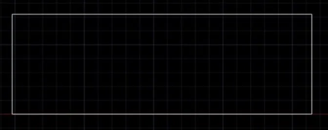
STEP2:
- enter O in command box
- type 5' as offset distnce and select the upper line and drag it downwards
- enter O in command box
- type 3' as offset distance and select the lower line and drag it upwards
- enter O in command box and type 10' as offset distance, select the left line and drag it inwards
- repeat this step for 4 more times
- enter O in command box and type 5' as offset distance, select the left line and drag it inwards
- repeat this step for 5 more times
- enter O in command box and type 5' as offset distance, select the 5' OFFSET LINE AND DRAG DOWNWARDS
- enter O in command box and type 3'6" as offset distance, select the 5' OFFSET LINE AND DRAG DOWNWARDS
- repeat this step one more time
- enter TR in command box
- trim all the unwanted lines
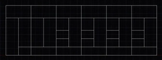
STEP3:
- Enter ST in command box
- select romans.shx in font name and height as 8", click ok
- click annotation tab and select single line and ribbon
- enter the text height as 8" and rotationn angle as 0
- for terrace to mumty, enter rotation angle as 90
- select multiline text in ribbon
- click symbol and select others
- click arial as font and select latin small letter alpha (U+0251)
- select it and press enter
- enter CO in command box and copy it in the required place
- select multiline text in ribbon
- click symbol and select others
- click arial as font and select latin small letter O with stroke (U+00F8)
- select it and press enter
- enter CO in command box and copy it in the required place
- enter textedit in command box to edit the text
- enter M in command box to move the text and diagram
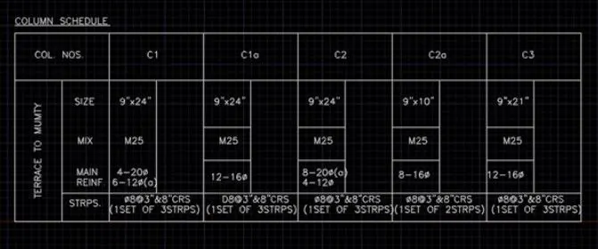
STEP4:
- enter REC in command box
- click the first corner point in C1 column
- click DIMENSIONS in command box
- enter 9" as length and 24" as width
- enter O in command box
- enter 1" as offset distance
- click the rect and drag it inside
- enter c in command box and type 1" as radius
- enter CO in command box
- copy the circle and place it at the dist of 6" and 5"
- place 5 circles in the single column of rectangle
- enter L and click at the two circles down side
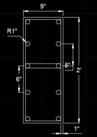
- enter O in command box
- type 3.5",1" and 4.8" as offset ddist and place it in the appropriate position
- enter F in command box
- select the corners and make the curve
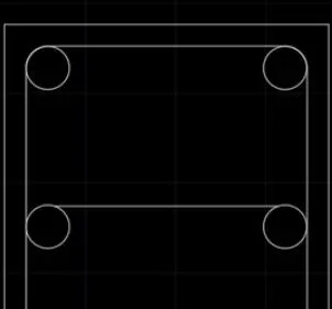
- enter F in command box
- select line and circle to make the curve
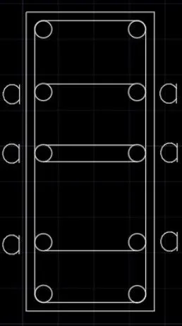
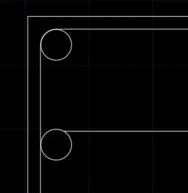
- enter CO in command box
- select the latin small letter alpha (U+0251) and place it in the outside of the rect
STEP5:
- Enter rec in the command box
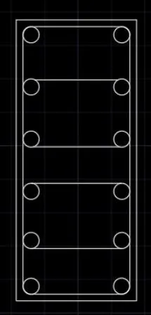
- click the first corner point as C1a column
- click DIMENSIIONS in command box
- enter 9" as length and 24" s width
- enter O in command box
- enter 1" as offset distance
- click the rec and drag it inside
- enter C in command box and type 1" as radius
- enter CO in command box
- copy the circles and place it in the corners
- enter CO in command box
- copy the circles at the dist of 2.5"
- place 6 circles at one column
- enter L in command box
- click at the two circles downside
- enter O in command box
- enter 4.5", 3" and 4.8" as offset dist and place all at the appropriate place
- switch off orthomode
- enter L and click theh nesrest point in circle
- type 3" as length of line
- enter O and type 3" as offset dist and drag at the opposite side
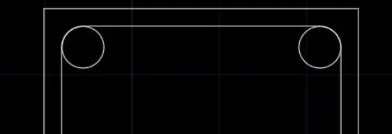
- enter F in command box
- select the corner to make the curve and give 1" as fillet radius
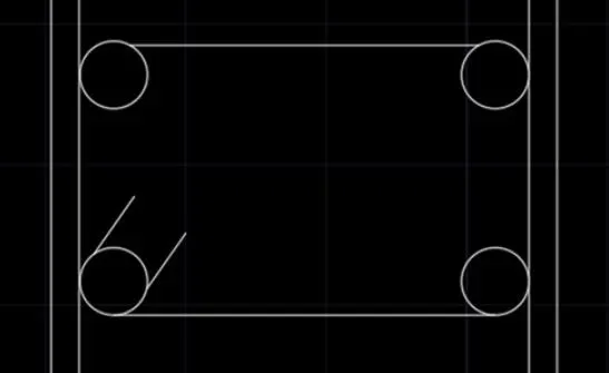
- enter F in command box
- select the line and circle to make a curve
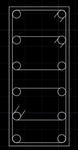
- repeat the same step fir other two bars at the top
STEP6:
- Enter REC in command box
- click the first corner ppoint in C2 column
- click DIMENSIONS in command box
- enter 9" as length and 24" as width
- enter O in command box
- enter 1" as offset distance
- click the rectangle and drag it inside
- enter C in command box and type 1" as radius
- enter CO in command box
- copy the circles and place it in the corners
- enter CO in command box
- copy the circles at the dist of 2.5"
- place 6 circles at one column
- enter L in command box
- click at the 2 circles downside
- enter O in command box
- entr 4.5",3" and 4.8" as offset dist and place all at the appropriate place
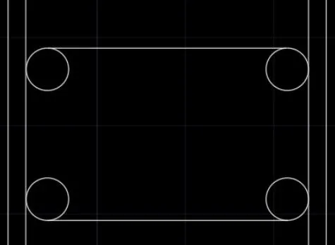
- enter F in command box
- enter 1" as fillet radius
- select the coorners of the rect
- enter F in the command box
- select the line and circle to make the curve
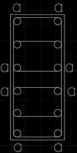
- enter CO in command box
- select the latin small letter alpha(U+0251) and place it in the outside of the rect

STEP7:
- Enter REC in command box
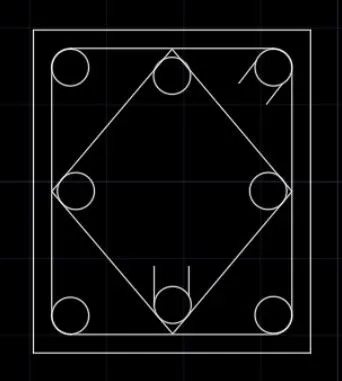
- click the first cornere point in c2a column
- click DIMENSIONS in command box
- enter 9" as length and 10" as width
- enter O in command box
- enter 1" as offset distance
- click the rectangle and drag it inside
- enter C in command box and type 1" as radius
- enter CO in command box
- copy the circles and place it in the corners
- enter CO in command box
- copy the circles at the dist of 3.5"
- place 3 circles at one column
- switch off ortho mode
- enter L and click at the midpoint of line
- connect the line as a diamond structure
- enter F in command box
- enter 1" as offset radius
- click the corners to make curve
- enter L and click the nearest point in circle
- type 3" as length of line
- enter O and type 3" as offset dist and drag at the opposite side
STEP8:
- Enter REC in command box
- click the first corner ppoint in C3 column
- click DIMENSIONS in command box
- enter 9" as length and 24" as width
- enter O in command box
- enter 1" as offset distance
- click the rectangle and drag it inside
- enter C in command box and type 1" as radius
- enter CO in command box
- copy the circles and place it in the corners
- enter CO in command box
- copy the circles at the dist of 2.5"
- place 6 circles at one column
- enter L in command box
- click at the 2 circles downside
- enter O in command box
- entr 4.5",3" and 4.8" as offset dist and place all at the appropriate place
- enter F in command box
- enter 1" as fillet radius
- select the coorners of the rect
- enter F in the command box
- select the line and circle to make the curve
RESULT:
the column schedule is created by lines using Autocad. the step by step procedure for creating the column schedule is also explained. the dimension is also entered in the diagram
2)WINDOW SCHEDULE:
AIM:
to create the window schedule using autodcad
INTRODUCTION:
The window schedule using autocad is created by lines, the procedure and result should be written after creatingthe window schedule
PROCEDURE:
STEP1:
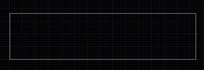
- Open the autocad software and click start drawing tab
- enter UNITS in command box
- select engineering in type 0'0" in precision and inches in units to scale inserted content, press ok
- switch on ortho mode
- enter L in command box
- enter 60'0" as first point
- enter 0',20' as next point
- enter @-60',0' as next point
- enter @0',-20' as next point
STEP2:
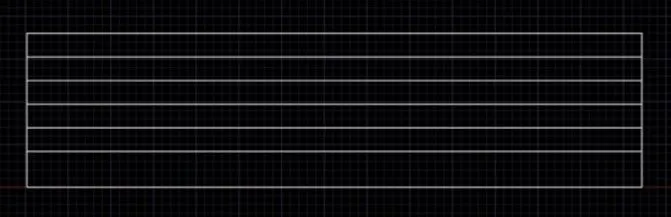
- enter O in command box
- enter 2.3' as offset distance
- select the upper horizontal line
- drag it downwards
- repeat the same step four more times
STEP3:
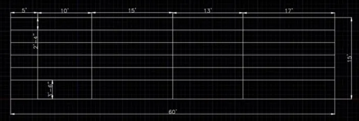
- Enter O in command box
- type 5' as offset dist
- select the left line and drag inwards
- Enter O in command box
- type 10' as offset dist
- select the 5' line and drag inwards
- Enter O in command box
- type 15' as offset dist
- select the 10' line and drag inwards
- Enter O in command box
- type 13' as offset dist
- select the 15' line and drag inwards
- Enter O in command box
- type 17' as offset dist
- select the 13' line and drag inwards
STEP4:
- Enter ST in command box
- select romans.shx in font name and height as 8", click ok
- click annotation tab and select single line in ribbon
- enter the text height as 8" and rotation angle as 0
- select multi line text in ribbon
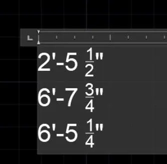
- enter the dimension
- click tab after entering 1/2, 1/4, 3/4
- enter textedit in command box to edit the text
- enter M in command box to move the text
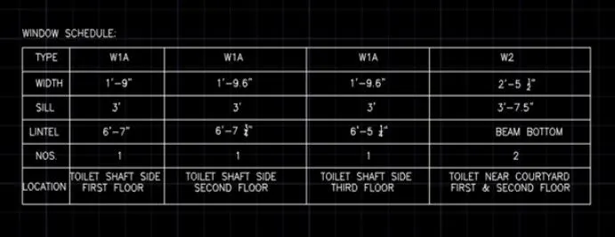
RESULT:
The window schedule is created bylines using autocad, the step by step procedure for creating window scgedule is also explained. the dimension is also entered in the diagram.
3) DRAWING TEMPLATE:
AIM:
To create the drawing template by using autocad
INTRODUCTION:
The drawing template using autocad is created by lines. the procedure and result should be written after creating the drawing template
PROCEDURE:
STEP 1:
- Open the autocad software and click start drawing tab
- enter units in command box
- select engineering in type 0'0" in precision and inches in units to scale inserted content, press ok
- switch on ortho mode
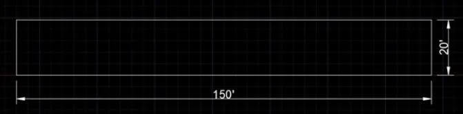
- enter L and type 0,0 in command box
- enter 150',0' as firsrt point
- enter 0',20' as next point
- enter @-150',0' as next point
- enter @0',-20' asa next point
STEP2:
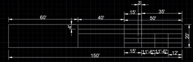
- enter O in command box
- enter 60' as offset distance
- select the left line and drag it inwards
- enterO in command box
- enter 40' as offset distance
- select the 60' line and drag it inwards
- enter O in command box
- entere 50' as offset distannce
- select the 40' line and drag it inwards
- enter O in command box
- enter 4' as offset distance
- select the upper line and drag it inwards
- repeat the same steps four more times
- enter O in command box
- enter 15' as offset distance
- select the 40' line and drag it in wards
- enter O in coammand box
- enter 11'6" a offset distance
- select the 15' line and drag it inwards
- repeat the same step one more time
- enter O in command box
- enter 12' as offset distance
- select the 11'6" line and drag it inwards
- enter O in command box
- enter 3' as offset distance
- select the 15' line and drag it left side
STEP3:
- enter ST in command box
- select romans.shx in font name and height as 8". click ok
- click annotation tab and select single line in ribbon
- enter the text height as 8" and rotation angle as 0
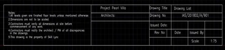
- enter the text in the drawing template
- enter textedit in the command box and edit the text
- enter M in the command box and move the text
RESULT:
The drawing template is created by lines using autocad. the step by step procedure for creating the drawing template is also created. the dimension is also entered in the diagram.
4) LIST OF DRAWING SCHEDULE:
AIM: To create the list of drawing schedule using autocad
INTRODUCTION: the list of drawing schedule using autocad is created by lines. the procedure and result should be written after creating the list of drawing schedule
PROCEDURE:
STEP1:
- open the autocad software and click start drawing tab
- enter units in command box
- select engineering in type, 0'0" in precision and inches in units to scale inserted content. press ok
- switch on orthomode
- enter L and type 0,0 in command box
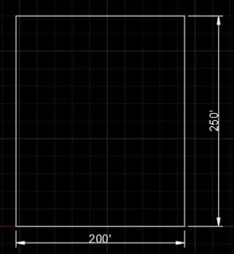
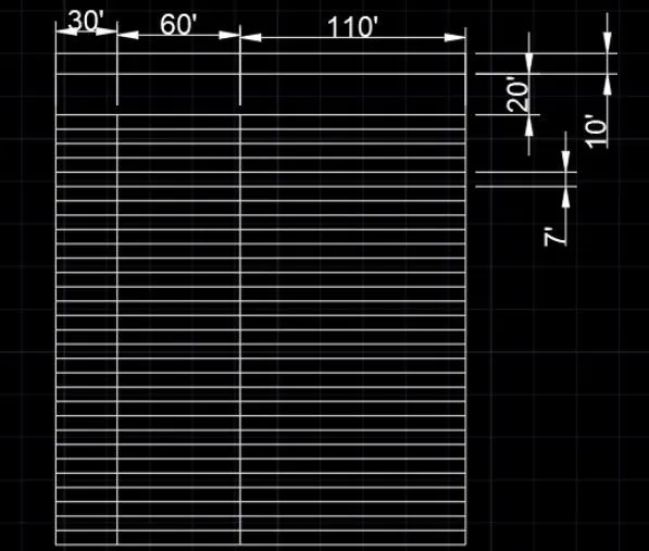
- type 200',0' in command box
- type 0',250' in command box
- type @-200',0' in command box
- type @0',-250' in command box
STEP2:
- Enter O in command box
- enter 30' as offset distance
- select the left line and drag it inwards
- enter O in command box
- enter 60' as offset distance
- select the 30' line and drag it inwards
- enter O in command box
- enter 110' as offset distance
- select the 60' line and drag it inwards
- enter O in the command box
- enter 10' as offset distance
- select the upper line and drag it inwards
- enter O in command box
- entere 20' as offset distance
- select the 10' line and drag it inwards
- enter O in the command box
- enter 7' as offset disrance
- select the 20' line and drag it inwards
- repeat the same step for 29 times
STEP3:
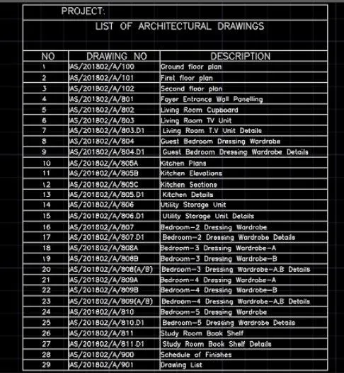
- enter ST in command box
- select romans.shx in font name and height as 8". click ok
- click annotation tab and select single line in ribbon
- enter the text height as 8" and rotation angle as 0
- enter the text in the drawing template
- enter CO in command box
- click array and enter 29
- select the text and press enter
- enter textedit in the command box and edit the text
- enter M in the command box and move the text
RESULT:
The list of drawing schedule is created by lines using autocad. the step by step procedure for creating the list of drawing schedule is also created. the dimension is also entered in the diagram.
5)BEAM DETAIL
AIM: To create beam detail using autocad
INTRODUCTION:
the beam detail using autocad is created by lines. the procedure and result should be written after creating the beam detail
PROCEDURE:
STEP1:
- open the autocad software and click start drawing tab
- enter units in command box
- select engineering in type, 0'0" in precision and inches in units to scale inserted content. press ok
- switch on orthomode
- enter L and type 0,0 in command box
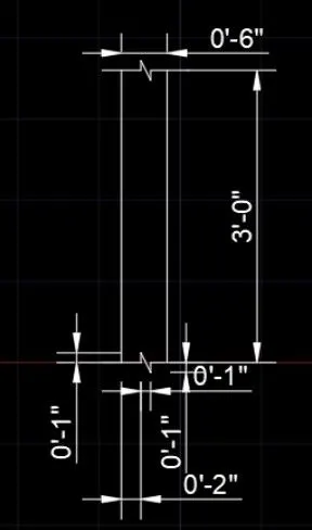
- type 6",0" as first point in command box
- type @0",1" as next point
- type @2",0" as next point
- type @0",-2" as next point
- type @6",0" as next point
- switch off ortho mode
- connect the upper and lower corner in the rect
- enter TR in command box
- delete the unwanted lines
- enter CO in command box
- enter 3' as distance and copy it
- enter L and enter 0,0
- enter @0',3' as next point
- enter O in command box
- enter 6" as offset distance
- select the tedt line and drag it right side
STEP2:;
- Enter REC in command box
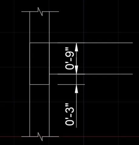
- enter 1.2" as first corner point
- click dimensions
- enter 6" as length and 1' as width
- extend the upper line of rectangle and enter 2' as next point
- enter O in command box
- enter 9" as offset dist and select the 2' line as next point
- enytter O in command box
- enter DIMS in command box
- click modify
- click line. enter 2" in extend beyond lines and 5" in offset from origin
- click symbols and arrows. enter 3" as arrow size
- clcik text. enter 3" as text height
- click primary units
- enter engineering in unit format and 0'0" in precision
- click set current. click close
STEP3:
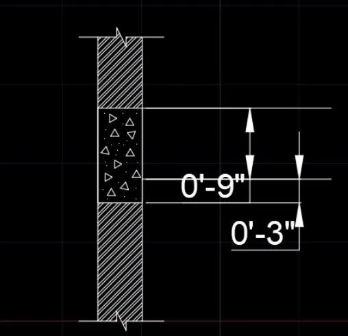
- Enter H in command box
- click the steel pattern in pattern panel in ribbon
- select the upper and lower rect and hatch the pattern
- click H in command box
- click the AR-CONC PATTERN in PATTERN panel in ribbon
- select the rect and hatch
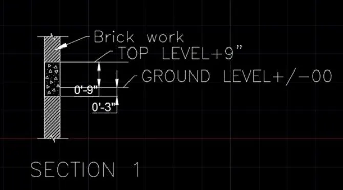
STEP4:
- Enter DT in command box
- enter 5" as text height and rotation angle as 0
- type the text
- enter MULTILEADER in command box
- click the object and type the text
- enter textedit in the command box and edit the text
- enter M in the command box and move the text
- save the file ctrl+s
RESULT:
The BEAM DETAIL is created by lines using autocad. the step by step procedure for creating the BEAM DETAIL is also created. the dimension is also entered in the diagram.