CREATION OF BASE BRACKET
Aim:
To create a Base Bracket Plastic Component through a given Class A Surface and perform Draft Analysis on the final plastic component.
Objectives:
Creation of Tooling Axis.
Creation of Class B and Class C surface.
Creating a solid part out of surface modeling
Draft Analysis of Class A surface and final plastic component.
Tool Used:
CATIA V5
Introduction:
In this project we are designing a base bracket using given class A surface. The approach includes creation of Class B surface keeping 2.5 mm thickness in mind for the complete component. The design also included Class C creation from the given parent surface.
Class A:
Class A surface are primary used in the automotive environment and rrefer to these surfaces which are visible to outside world or to the humans..Class A surfaces are those surfaces ,which are vivible to us (interior/exterior) and have an shape and high surface quality
Class B
class B are secondary surfaces that goes fee sometimes ,but are less impoortant sucha s the inside of your glovebox,ash tray etc., these must be smooth and as well ,but aare not held to the standard thst class A surfaces
- CREATE POINT WITH THE HELP OF CIRCLE ELIPSE COMMAND IN POINT OPTION
- TAKE A LINE DRAW LINE WITH THAT CIRCLE AND MAKE IT BOLD AND DOTTED..
- First ensure the class-A surface is properly joined and has no discontinuity on it. For this we can use boundary command or join command.
- Analyze the model manually or visually to see which direction is most suitable for tooling axis.
- As in 3D view we can see 2 holes and a flat surface, we can directly take the tooling axis perpendicular to that. But to be sure,let us analaze from all the views. The below images of the front side and top views shows the areas that we have to keep in mind while choosing tooling axis. As from X we cannot see one hole so we cannot take axis along this. In Y we cannot see any holes so here too we cannot take tooling axis. But in Z we can see 2 holes and flat surface so we can take tooling axis.
- Intersect the ZX plane of the axis system with the input and we can see that there is no surface that can create problem during tooling in this direction.
- Intersect ZY plane and we are unsure of these two surfaces, so we make a line and bisect them both and this will be our tooling axis which, not so surprisingly, is the same as our guessed tooling axis.
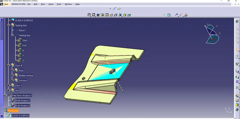
-
CLASS-A Surface
- Class-A surface means visible surface. It gives the aesthetic of the component which is created by the styling team and gives to the part design engineer to create the part with all engineering aspects.
CLASS-B Surface- Class-B surface means the thickness of a part it is not visible and is inside part. In other words, the Class-B surface is a surface below a certain thickness from the class-A surface. This is the surface that contains engineering aspects of a model.
CLASS-C Surface- The surface that joins class-A and class-B surfaces are class-C surfaces. Class C is often specified for interior surfaces not readily visible, surfaces that will be covered by another part when assembled
- Tooling axis: The direction in which the mold or core and cavity opens is the tooling axis.
-
PERFORM THE DRAFT ANALYSIS-1:-Make sure the view mode of the part is in material shadingThen do to insert the menu and insert the featured draft analysis toolPick the compass and align it with the tooling axis by dragging it.Then lock the draft direction and perform draft analysis by clicking on the component.The green color shows the positive daft tooling direction and the given surface passes the draft analysis.Click on the analyses under the running point to check the draft analysis on the individual faces. It shows how much draft on specific points when we move the cursor point.Representation of Color variations in the draft analysisGREEN COLOR - Positive Draft (3 degrees)RED COLOR - 0-degree draftBLUE COLOR - Negative Draft
- Extract the ribs from the class-A surface one by one.
- Untrim the extracted surfaces
- Extrapolate the untrimmed surfaces with a required length
- Trim the extrapolated surfaces to achieve the desired rib shape
- Then offset the trimmed surface to 2.5mm downwards
- Extract the slant surface from the class-a surface
- Untrim the extracted surface
- Extrapolate the untrimmed surface
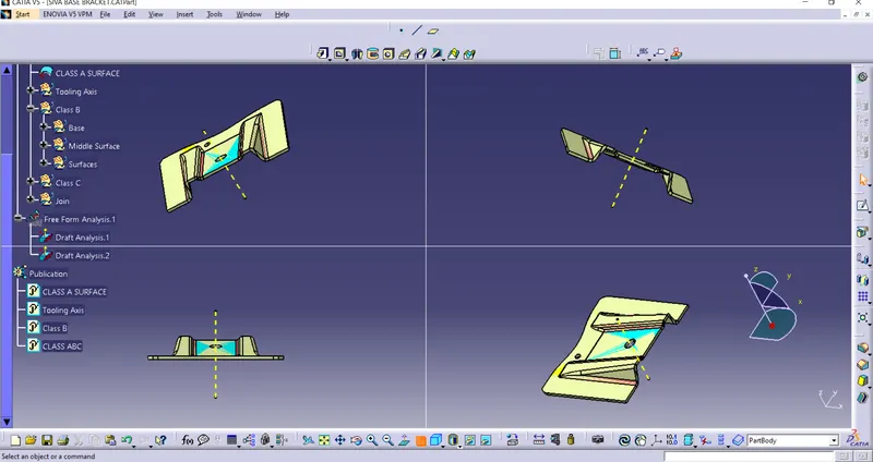
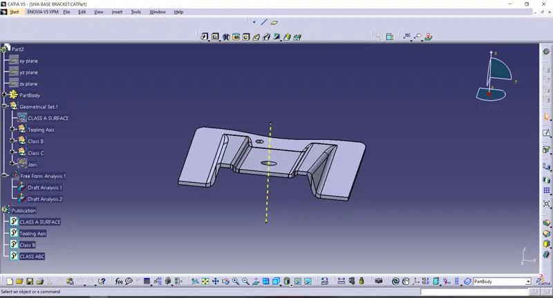
- Go to insert,analysis, feature draft analysis.
- Align the tooling axis with the compass.
- Click on the surface and see that the surface is within the permissible limit of the draft values.
- The surface should be green and in the column proper value (2.9deg) should be inserted.
- Changee the colurs red as blue and blue as red.
- Extract
- Un-trim
- Trim
- Extrapolate
- Offset
- Edge fillet
- Boundary
- Sweep
- Join
- Close (part design)
TREE STRUCTURE:
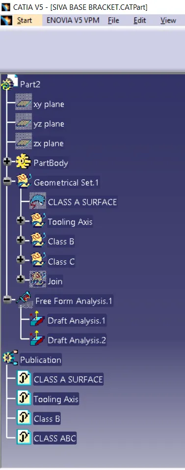
CONCLUSION:
Creation of base bracket using catia V5 was completed as per the required standards.