CREATION OF A BASE BRACKET
AIM: To create a Base Bracket Plastic Component through a given Class A Surface and perform Draft Analysis on the final plastic component.
OBJECTIVES:
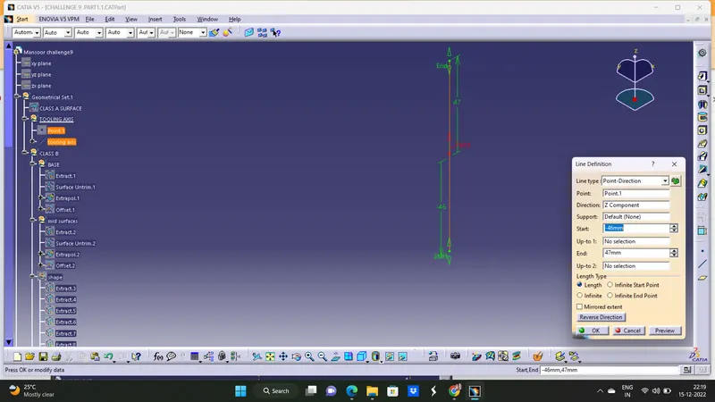
Creation of Tooling Axis.
Creation of Class B and Class C surface.
Creating a solid part out of surface modeling
Draft Analysis of Class A surface and final plastic component.
SOFTWARE USED: CATIA V5
INTRODUCTION: In this project we are designing a base bracket using given class A surface. The approach includes creation of Class B surface keeping 2.5 mm thickness in mind for the complete component. The design also included Class C creation from the given parent surface.
TOOLING AXIS:
These tooling axes are used for creation of tooling axis by bisecting method where the two lines and point will be selected as inputs.
DRAFT ANALYSIS:
To perform draft analysis, click on Insert >>Analysis >> Feature Draft Analysis.
Draft analysis is done after determining the tooling axis, draft analysis is used to check whether the minimum draft (3 degrees) is maintained or not. Compass is used to define the draft direction. If the minimum draft 3 degree is provided the whole component changes in to green colour.
Class A:
Class A surface are primary used in the automotive environment and rrefer to these surfaces which are visible to outside world or to the humans..Class A surfaces are those surfaces ,which are vivible to us (interior/exterior) and have an shape and high surface quality
CLASS B :
class B are secondary surfaces that goes fee sometimes, but are less impoortant sucha s the inside of your glovebox,ash tray etc., these must be smooth and as well ,but aare not held to the standard thst class A surfaces.
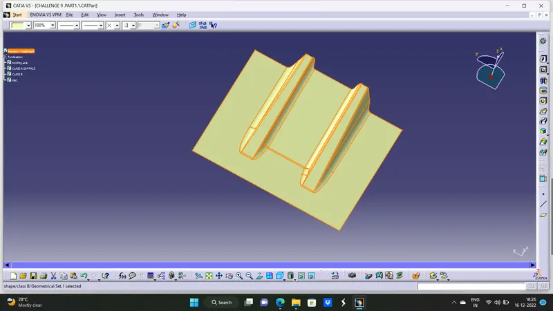
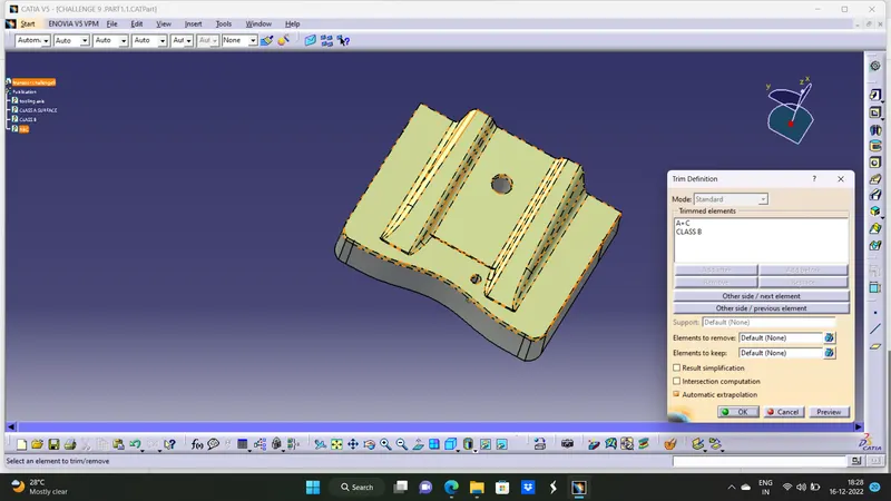
creation of ABC
click on insert geometrical set AC under input and then click on ok
--Define the ABC
join everything(class A,class C,class B) using join command
after joing all publish class c
CONCLUSION
The base bracket was sucessfully completed as per the standards.
Submitted By
SHAIK. MANSOOR