Creating Walls, Partition walls and Floors for a residential layout using REVIT
Q1. Use the project file created from Week 2. Use it for this assignment. Based on your layout from week 2, using floor tool under architecture tab and select the floor with appropriate material and thickness using the property browser create a layout in the Ground floor Level Align the floor plan with grids created from week 2.
STEPS FOR CREATING A FLOOR
Click Architecture tab Build panel Floor drop-down (Floor: Architectural). • Draw the floor boundaries, using one of the following methods:
Pick walls: By default, Pick Walls is active. If it is not active, click Modify | Create Floor Boundary Tab Draw panel (Pick Walls). Select walls in the drawing area to use as floor boundaries.
Sketch boundaries: To sketch the profile of the floor, click Modify | Create Floor Boundary Tab Draw panel, and select a sketching tool. See Sketching.
The floor boundary must be a closed loop (profile). To create an opening in the floor, you can sketch another closed loop where you want the opening to appear.
• On the Options Bar, for Offset, specify an offset for the floor edges
• Note: When you are using Pick Walls, select Extend into wall (to core) to measure the offset from the wall's .core. Click Finish
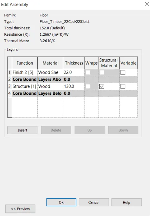
• Select the flooring type as wooden flooring and thickness of flooring as 152mm.
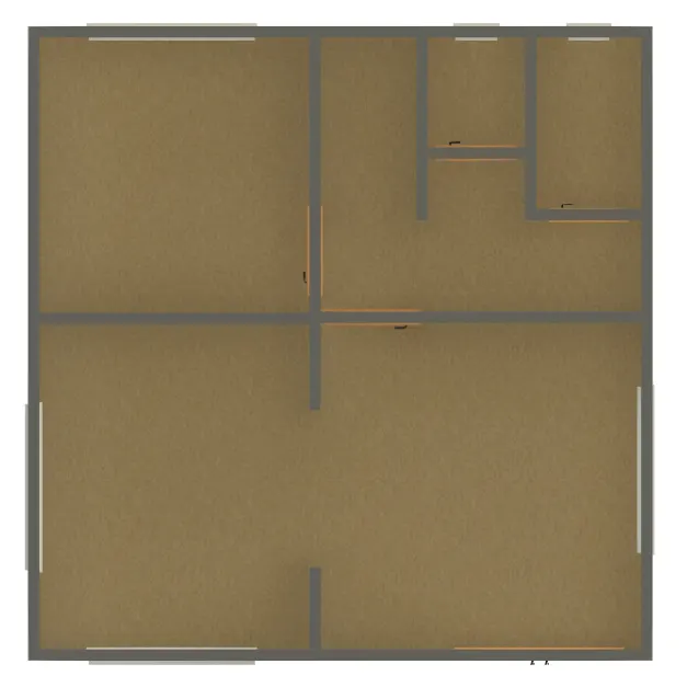
PROPERTIES OF FLOOR.
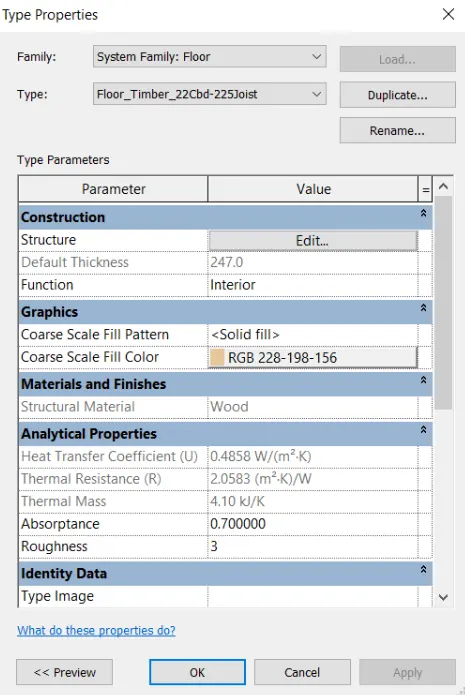
DETAILS OF FLOORING
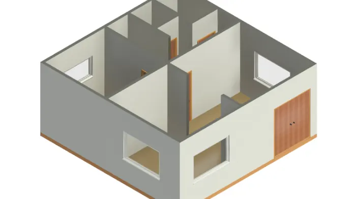
TOP VIEW
STEPS FOR ALIGNING THE GRIDS
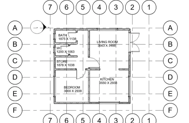
Navigate to Architecture > Grid or Structure > Grid. Now click once at the start and again at the end of the grid you wish to set up. This should snap to a vertical. Set up however many you need, at approximate spacings this way. Revit labels them 1, 2, 3... Now draw a horizontal grid line. Double click the number and enter the letter "A" instead and hit Enter. Now when you create further horizontal grids they will be labelled A,B,C... Now select each and modify the spacing between them.
GRIDS ALIGNED TO FLOOR
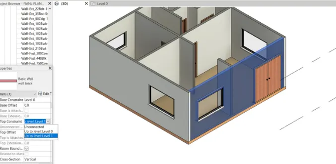
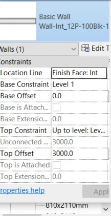
Q2. Add walls based on the floor layout. Pick lines or use the draw tool to modify the boundary of walls. Use the property browser to select appropriate material and thickness for walls. After creating the walls verify using the property browser to see if the top and bottom of the walls are constrained.
MODIFICATION OF WALLS
• To modify the wall, select the wall and use tools on the Modify | Walls tab. To change its underlying shape, click Model panel (Edit In
Place).
• To change its instance properties, select the wall and edit the values on the Properties palette.
• To change its type properties, select the wall and click Modify tab Properties panel (Type Properties). To duplicate an in-place wall, select the wall, and copy it.
• When you copy an in-place wall, a new wall type is created for the copy. Some type properties are not carried forward to the new
wall type.
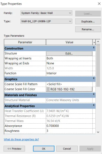
• Select wall type and structure as concrete masonry units.
WALL CONSTRAINTS
TYPE OF WALL CONCRETE MASNORY UNITS
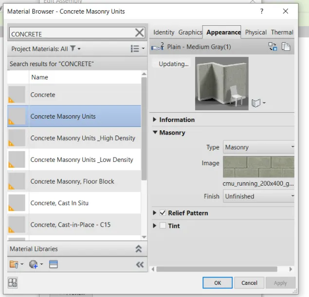
WALL DETAILS
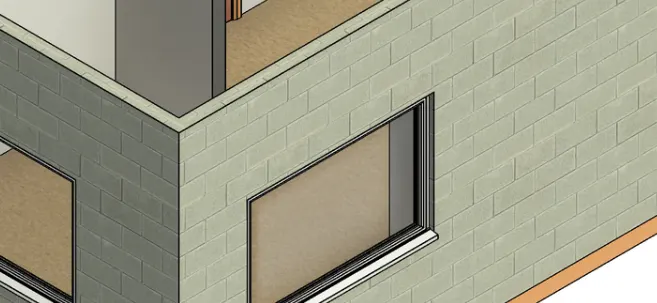
LEVEL OF WALLS
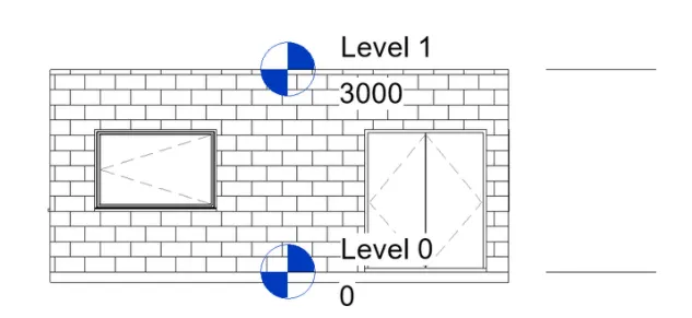
Q3. Copy the model elements (wall, floor) modelled to Ground Floor Level and paste it aligned to First Floor Level. Use modify tab to utilize copy and paste options to align elements to a different level.
Select elements to be copied in the active view (plan, section/elevation or 3D view).
Copy to Clipboard (CTRL+C) or from the Modify ribbon-Clipboard panel, choose Copy . On the Modify ribbon > Clipboard, click the drop-down arrow under the Paste command
• Select "Aligned to Selected Levels™
• Choose the Target level (i.e., Level 2)
• Switch to a 3D View to see the results
COPIED PLAN IN 3D
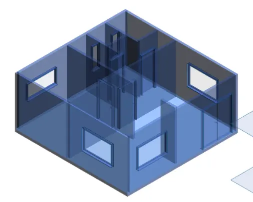
ALIGNING PLAN TO UPPER FLOOR
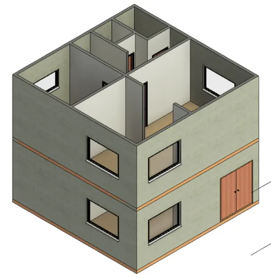
Q.4Use interior partition walls to create separate rooms within your residential unit. The model must include the following rooms
a. Living Room/ Drawing Room ( 15’ X 18’)
b. Dining Room (9’ X 11’)
c. Bed Room ( 9’ X 12’ and 15’ X 11’)
d. Rest Room ( 10’ X 12’ )
e. Kitchen (8’ X 10’)
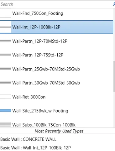
DETAILS OFINTERIOR WALL
Q5. Placing the components to residential unit.
- Adding the roof to building
- Display a floor plan view or a reflected ceiling plan view.
- Click Architecture tab Build panel Roof drop-down (Roof by Footprint).
- On the Draw panel, select a sketch or pick tool. To edit roof properties before sketching, use the Properties palette.
- Sketch, or pick, a closed loop for the roof..
- Specify slope defining lines. To change the slope definition of a line. select the line and, on the Properties palette, click Defines Roof Slope. You can then change the slope value.
- When a roof line is set to slope defining this symbol appears adjacent to it.
- Click (Finish Edit Mode), and then open a 3D view
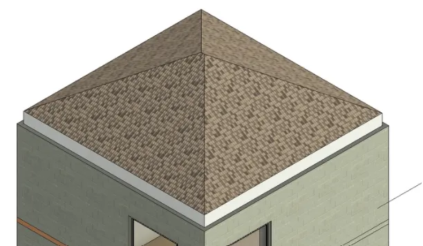
Placing of components in residential building
- Go to the load families option in the insert tab.
- Insert various types of families.
- Place the various components in the building.
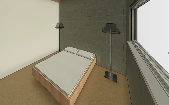
BEDROOM VIEW
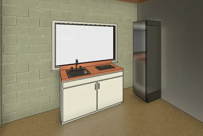
KITCHEN VIEW
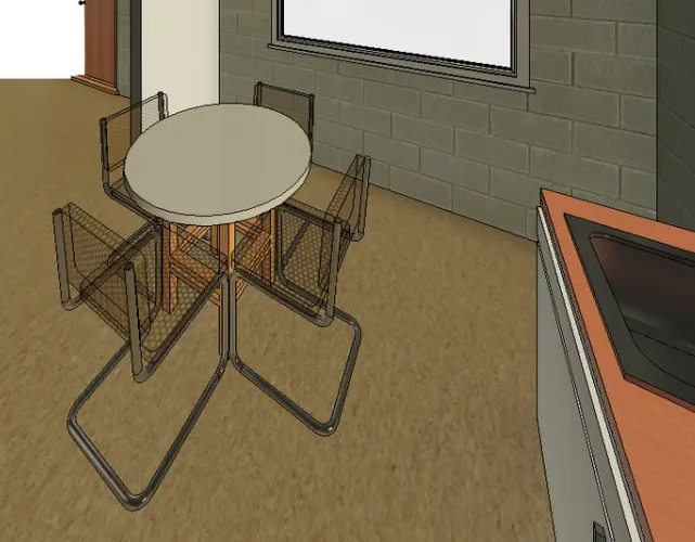
DINING VIEW
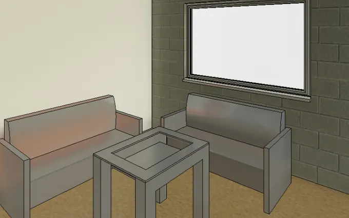
LIVING ROOM
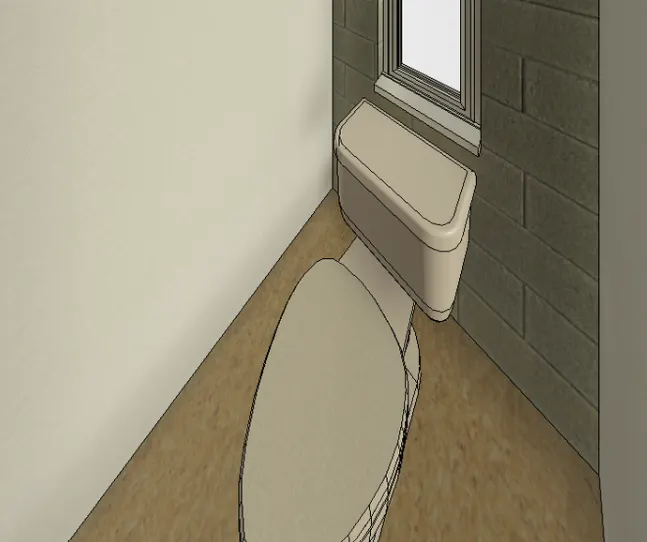
WC