Creating Walls, Partition walls and Floors for a residential layout using REVIT
CREATING WALLS, PARTITION WALLS, AND FLOORS FOR A RESIDENTIAL LAYOUT USING REVIT
AIM -
- TO STUDY THE CREATION OF WALLS, PARTITION WALLS, AND FLOORS FOR A RESIDENTIAL LAYOUT USING REVIT
- THE TARGET OF THESE PROJECTS IS TO SOLVE ALL THE TASKS GIVEN.
INTRODUCTION -
Autodesk Revit is a building information modeling software tool for architects, landscape architects, structural engineers, mechanical, electrical, and plumbing (MEP) engineers, designers, and contractors. The original software was developed by Charles River Software, founded in 1997, renamed Revit Technology Corporation in 2000, and acquired by Autodesk in 2002. The software allows users to design a building and structure and its components in 3D, annotate the model with 2D drafting elements, and access building information from the building model's database. Revit is 4D building information modeling capable with tools to plan and track various stages in the building's lifecycle, from concept to construction and later maintenance and/or demolition
Tools and their function -
- Navigation - we can use the mouse wheel, Project Browser, or View Cube to open a view and navigate to different areas of the model.
- The Project Browser - Located on the lower left of your Revit screen, the Project Browser acts as a table of contents for your project. Use it to navigate and open views of the model. You can organize, sort, filter, and customize the Project Browser to support your workflow.
- The Properties - The Properties palette lets you view and modify parameters for selected elements. If no element is selected, it displays the properties of the current view. The palette appears by default to the left of the drawing area above the Project Browser.
- Temporary Dimensions - As you create or select geometry, Revit displays temporary dimensions around the element. You can use temporary dimensions to dynamically control the placement of elements. Learn more about Temporary Dimensions
- Levels – Levels are finite horizontal planes that act as references for level-hosted elements, such as roofs, floors, and ceilings.
- WALL - Use a Wall tool to create a non-bearing wall or a structural wall in the building model. Like other basic elements in a building model, walls are instances of predefined system family types, which represent standard varieties of wall function, composition, and thickness
OBJECTIVE -
THE MAIN OBJECTIVE OF THESE PROJECTS IS TO UNDERSTAND HOW TO CREATE A WALL AND PARTITION WALLS AS WELL AS FLOORS IN A RESIDENTIAL LAYOUT.
TASK 1 - Use the project file created from Week 2. Use it for this assignment. Based on your layout from week 2, use the floor tool under the architecture tab and select the floor with appropriate material and thickness using the property browser to create a laYOUT on the Ground floor Level. Align the floor plan with grids created from week 2
PROCEDURE -
STEP 1-
- Go to the Window search box to open a Revit workspace.
- In the window search bar type REVIT, and the icon of the Revit application will show on the screen
- Click on the icon of REVIT, the application of Revit will open and the user interface of Revit will show on the screen.
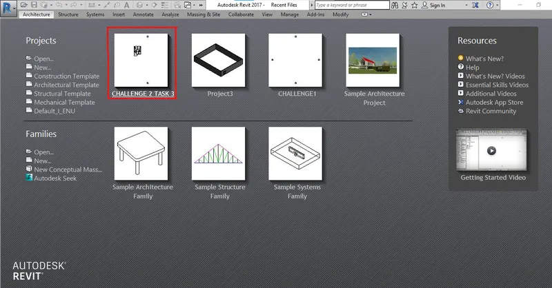
- Click on the existing project created in week 2 challenges [ project shown in the red box in the picture].
STEP 2-
- The existing project will open
- Click on 3D view to see the building in all directions.
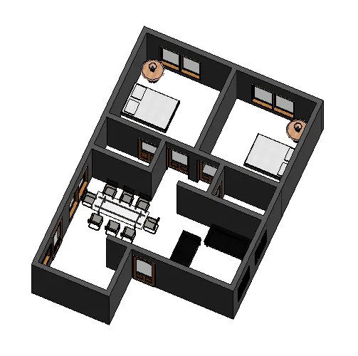
STEP 3-
- In the ribbon architecture tab is present
- In the architecture drop down there is an icon of the floor tab as shown in the picture.
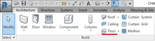
STEP 4-
- Click on the FLOOR TAB
- A new dialog box will open to modify the toolbar
- Click on the rectangular symbol as shown in the picture.
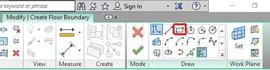
STEP 5-
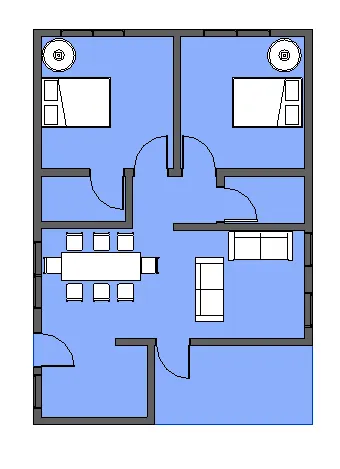
- Go to the ground plan level and draw the rectangle further to om corner of the building and specify the second point of the rectangle as the boundary of the floor and press enter.
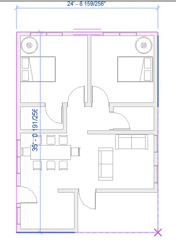
STEP 6-
- The floor is created as shown in the picture in blue color.
STEP 7-
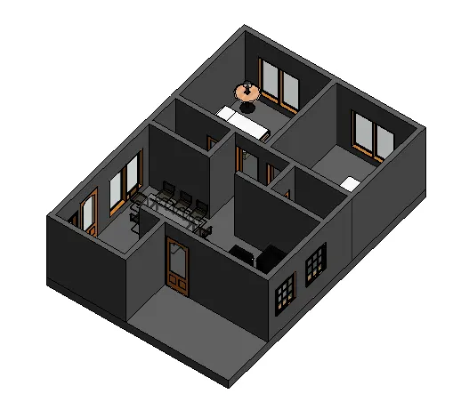
- Go to the 3d view to see the floor.
STEP 8-
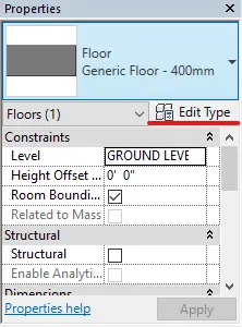
- To change the material and thickness of the floor go the properties.
- In the properties there is a tab of EDIT TYPE.
- Click on edit type
STEP 9-
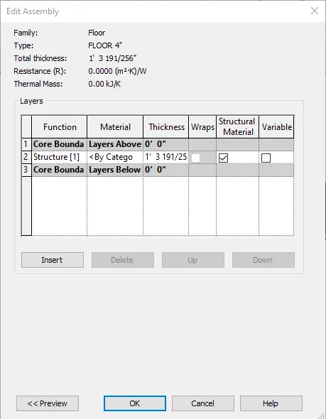
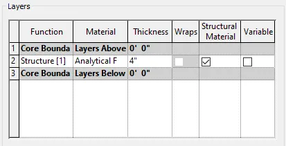
- A new dialog box will open name as Edit Assembly
- in the edit assembly dialog box there is a tab for material and thickness.
STEP 10-
- Click on the material tab a new dialog box will open and select the material as per required. Here, I choose Analytical flooring
- Now click on the thickness and choose the thickness size as 4".
STEP 11-
- Press OK and Click on APPLY
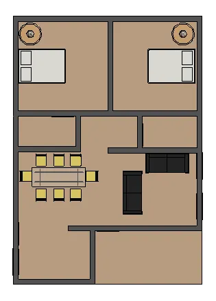
- The material and thickness are applied to the floor.
STEP 12 -
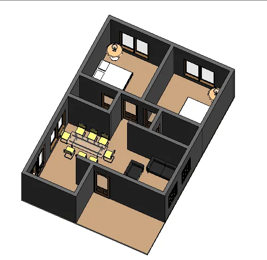
- Click on the 3D view to see the floor in a different view.
STEP 13 -
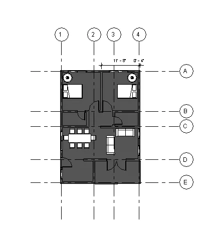
- Go to the architecture tab and click on GRID
- Select the line from the modify that and create the one horizontal grid name as A and one vertical line name as 1
- Now again select a grid and select the pick line option from the modify tab and specify distance as and select horizontal line and create a grid from A to E
- again select a grid and select the pick line option from the modify tab and specify the distance and select a vertical line and create a grid from 1 to 4.
TASK 2 - Add walls based on the floor layout. Pick lines or use the draw tool to modify the boundary of walls. Use the property browser to select the appropriate material and thickness for walls. After creating the walls verify using the property browser to see if the top and bottom of the walls are constrained.
PROCEDURE -
STEP 1-
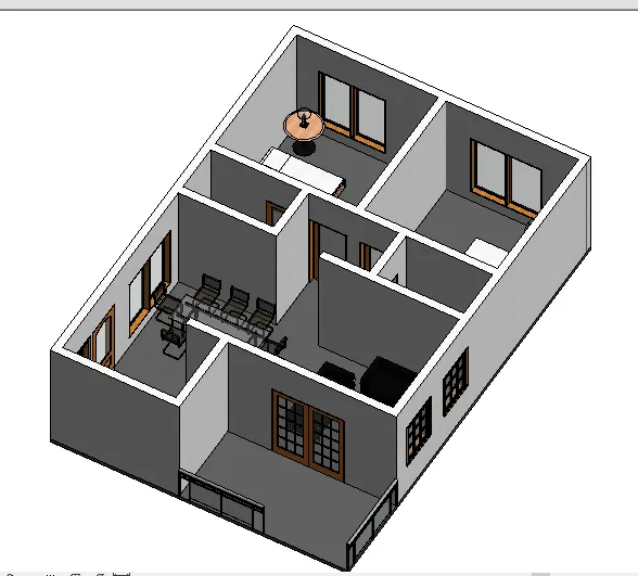
- Open the existing project created in the last task where we already created the wall as shown in the picture.
STEP 2-
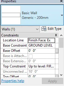
- Select the wall
- To change the material and thickness of the floor go the properties.
- In the properties there is a tab of EDIT TYPE.
- Click on edit type
STEP 3-
- A new dialog box will open name as Edit Assembly
- in the edit assembly dialog box there is a tab for material and thickness.
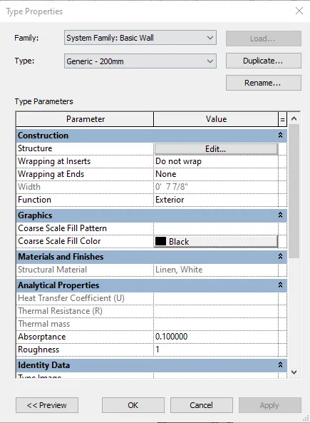
STEP 4-
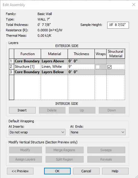
- Click on the material tab a new dialog box will open and select the material as per required. Here, I choose LINEN, WHITE
- Now click on the thickness and choose the thickness size as 9".
RESULT -
a. Based on your observation, what is beneficial for connecting walls with associated levels rather than being Unconnected
b. Which option is convenient for modeling walls, By Height or By Depth?
TASK 3 - Copy the model elements ( wall, floor ) modeled to Ground Floor Level and paste it aligned to First Floor Level. Use modify tab to utilize copy and paste options to align
elements to a different level
PROCEDURE -
STEP 1-
- Open the last model created as shown in the picture.
- And select the complete model with wall and floor and all the components.
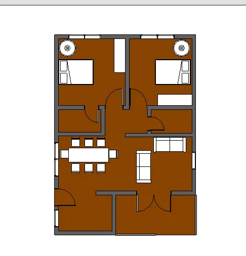
STEP 2-
- After selecting the complete model a modify tab will open
- There is an icon of COPY TO CLIPBOARD as shown in the picture in the red line.
- Click on the icon.

STEP 3-
- Now click on the PASTE drop down there is a tab of ALIGNED TO SELECTED LEVEL
- click on that tab a new dialog box will open
- Select the floor level as The IRST FLOOR
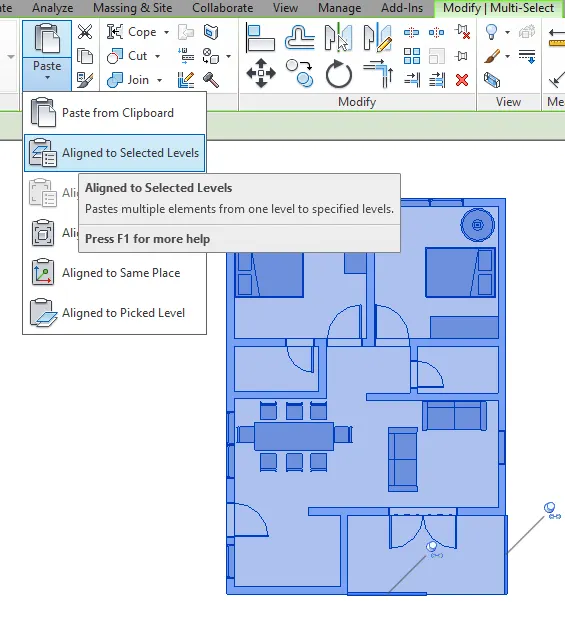
STEP 4-
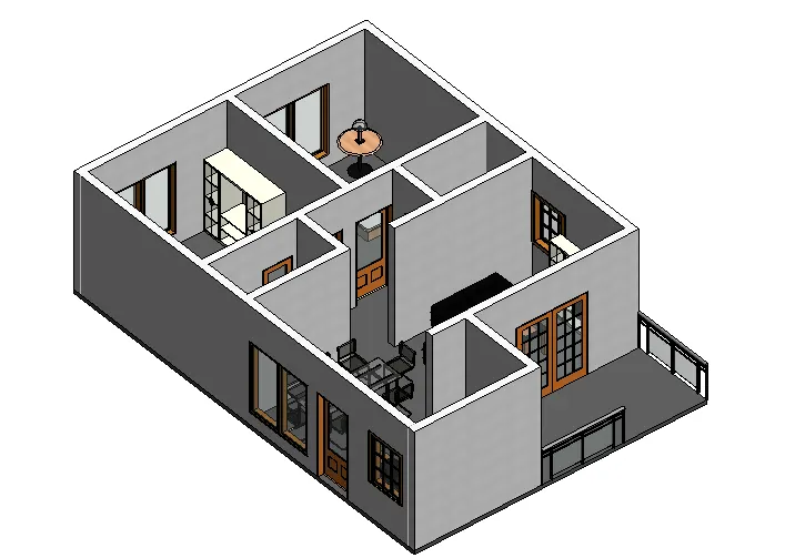
- Go to the 3D view to see the elevation of the building where you can the ground level plan is copied to the o first floor.
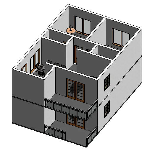
TASK 4 - Use interior partition walls to create separate rooms within your residential unit. The model must include the following rooms. The above is for examples. You can use them or use your measured entities to create your model based on your layout. You may include entran y walkway, Patios, or Guest
rooms based on your creativity and purpose of modeling. Convert units if you are using the metric system
PROCEDURE -
STEP 1-
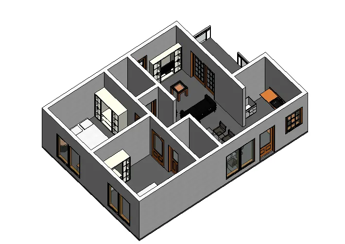
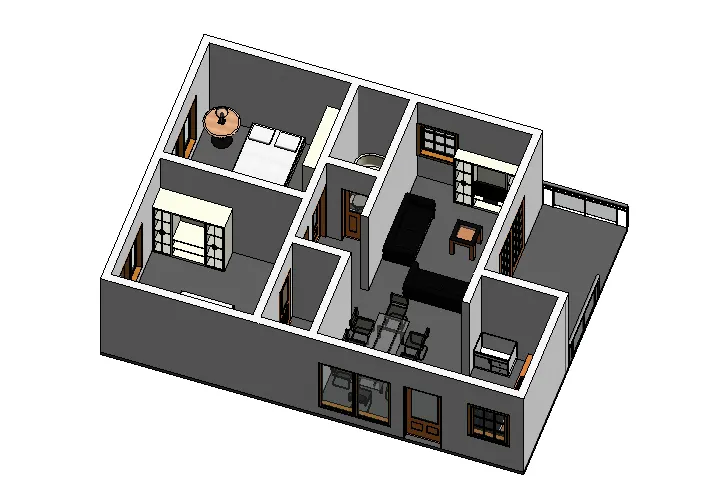
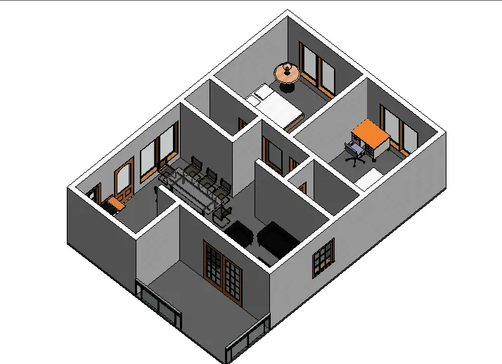
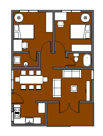
- The plan is created with a witbedroomsroom, 2toilets, a kitchen, a dining room, and a living hall.
- All the room name is provided with dimension.
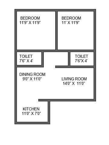
STEP 2-
- Go to the 3D view to see the elevation of the building
TASK 5 - Based on the week 2 assignment, the components to be included in a residential unit were inserted to intone the Revit file. Place these components in appropriate locations to add details to your residential model
a. Place Doors and windows on the wall at appropriate locations
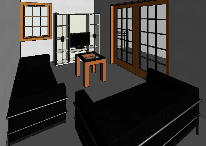
b. The Living Room must include a furniture set, couch table and TV desk, and shelf cabinets
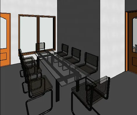
c. The Dining Room must include a table and chairs serving the purpose of eating
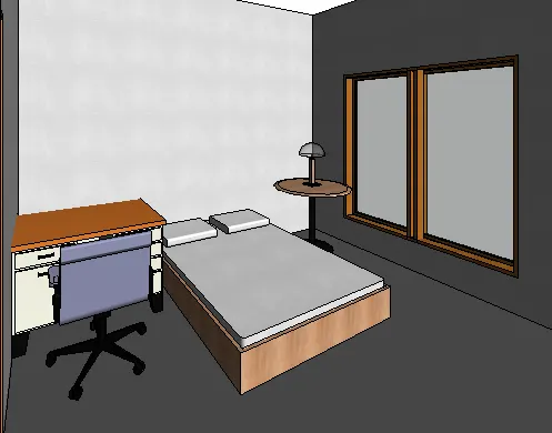
d. Bed Room must include a bed set, shelf, lighting, individual study desk, and chair
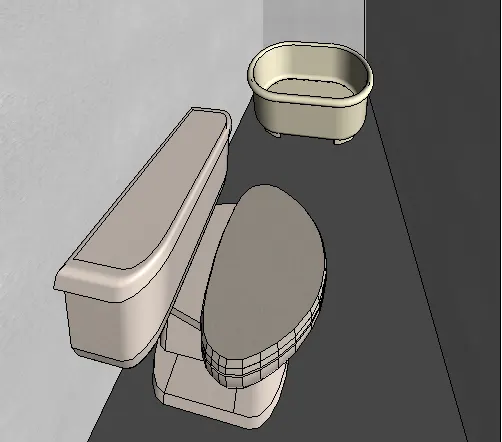
e. The restroom should include an ude bathtub and plumbing fixtures discussed in class
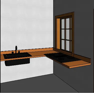
f. The kitchen should include countertops, a gas stove cabinet, and shelves to store food items
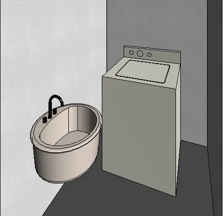
g. The wash/storage room can include washing machines and shelves to store clothes
All the components are available in Revit Library. Use them to place at appropriate locations to add details to your model. Use 3D navigation to check the model and its authenticity on an areal-time basis to verify the model
PROCEDURE -
STEP 1-
- Go to the ribbon there is an INSERT toolbar
- Click on insert toolbar where LOAD FAMILY is present
- Click on load family a new window will open and select the families that we need for our project
- Such as door, window, furniture set, couch table, tv desk, and self cabinet and all the furniture mentioned in the task.

STEP 2-
- All the furniture is placed from the property's browser as shown in the layout.
- Now click on 3d view and Camera to check every element and component of each room present in the palm.
DOOR AND WINDOW
LIVING ROOM -
DINING ROOM-
BEDROOM -
WASH ROOM -
KITCHEN -
WASH AND STORAGE ROOM
FINAL RESULT -