Creating various 3D Models like Furniture, Footing, Girder, Column drop with panel and Gable Wall in AutoCad
1)
AIM:
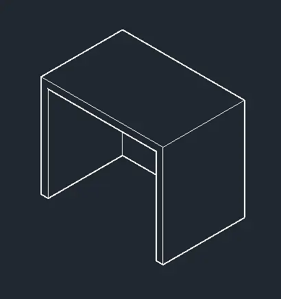
- To create a 3D Furniture element as shown in the Figure.
- Assume dimensions which are missing.
PROCEDURE:
- Using Worskspace switching icon 3D Basics workspace is set.
- Using LINE tool the outline is formed.
- Inside the outline a rectangle is created using RECTANGULAR command.
- Using BOUNDARY a surface is created within the outline.
- It is then extruded to form a solid using EXTRUDE command.
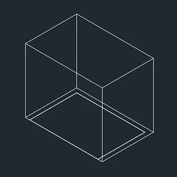
- The inner rectangle is also created as a region using REGION command and selecting it as the object.
- It is extruded using ECTRUDE command to the required height.
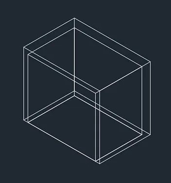
- The inner solid is then subtracted off using SUBTRACT command to get the required solid.
- It is displayed using HIDE option from Visual styles dropdown.
FINAL RESULT:
The required 3D furniture element has been created as per dimensions.
2)
AIM:
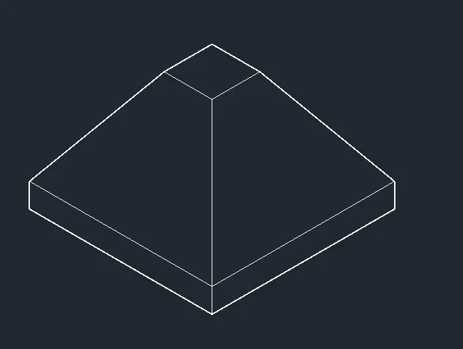
- To create the 3d Model of an Isolated footing as shown in Figure.
PROCEDURE:
- UN command is given and units are set to engineering.
- The precision is set to 0'-0'0".
- A rectangle of given dimensions is drawn using RECTANGULAR command.
- It is then offsetted using OFFSET command and copied and moved in the Z axis using COPY command.
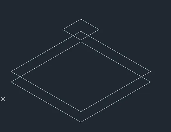
- The edges are then joined using LINE command.
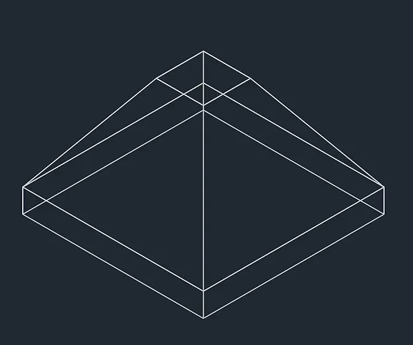
- They are then created into a solid by using #DFACE command and selecting the edges.
- It is displayed using HIDE option from the visual styles dropdown.
FINAL RESULT:
The required Footing has been created.
3)
AIM:
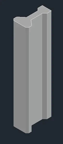
- To create the 3D view of the AASTHO Type Girder.
PROCEDURE:
- The outline is created using Top view from view cube.
- It is created as per the given dimensions with LINE, OFFSET and TRIM tools.
- The Home icon is clicked on the view cube.
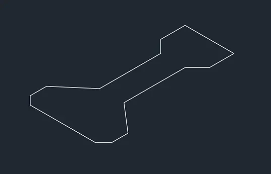
- BOUNDARY command is used to create a region within the outline.
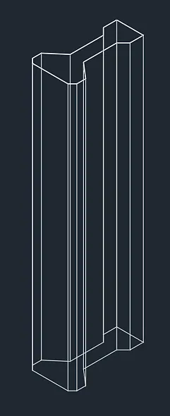
- It is then extruded as per dimensions using EXTRUDE command.
FINAL RESULT:
The required 3D view of the AASTHO Type Girder has been created and represented in the Shaded visual style.
4)
AIM:
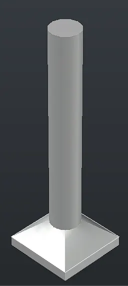
- To create a 3d Model of a drop column with panel as shown in section and isometric view.
PROCEDURE:
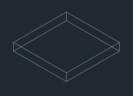
- A rectangle is created of required dimensions using RECTANGULAR command.
- It is then converted into region by REGION command and selecting it as object.
- It is then extruded using EXTRUDE command for required dimensions.
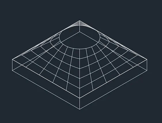
- Another rectangle of same imensions is drawn using RECTANGULAR.
- A circle is drawn from the geometric center of the rectangle using CIRCLE command and moved for required distance in Z axis using MOVE command.
- LOFT is selected from ribbon and the surface is created using the shapes.
- It is then placed on the previously created cuboid using MOVE command.
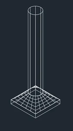
- A circle is created on top of the previous circle using CIRCLE command.
- It is extruded using EXTRUDE command for required dimensions.
FINAL RESULT:
A 3d Model of a drop column with panel as shown in section and isometric view has been created and is displayed in the Shaded visual style.
5)
AIM:
- To create the 3d model of a wall as shown in Figure.
- Consider wall thickness as 9”.
PROCEDURE:
- Using LINE and TRIM commands the outline of the Wall is created.
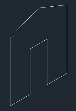
- BOUNDARY command is used to create a region within its boundaries.
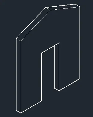
- It is then Extruded using EXTRUDE command.
FINAL RESULT:
The 3d model of a wall as shown in Figure of wall thickness as 9” is created and displayed in the Shaded visual style.