Creating various 3D Models like Furniture, Footing, Girder, Column drop with panel and Gable Wall in AutoCad
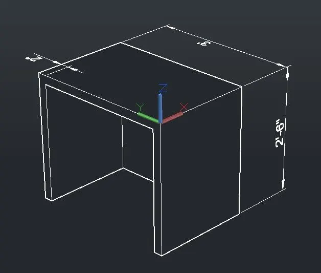
1. Create a 3D Furniture element as shown in the Figure. Assume dimensions which are missing.
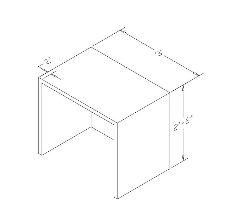
AIM: A 3D furniture element is created in AutoCAD as given in figure
INTRODUCTION: The 3D model is created in 3D modeling workspace by using 2D and 3D tools. The procedure of the drawing is explained in detail with the figure and final result is given
PROCEDURE:
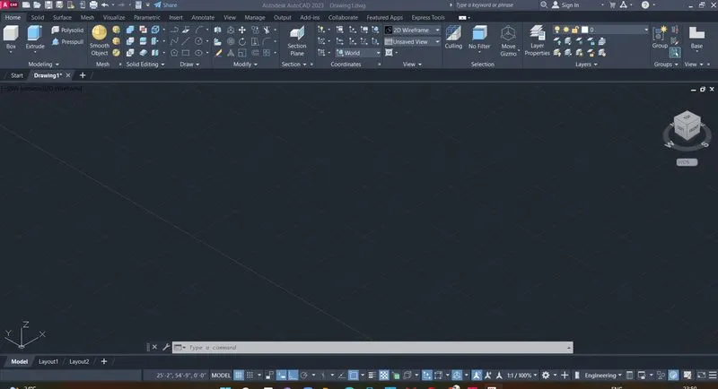
STEP 1) SELECTION OF DRAWING MODEL
- Open AutoCAD software
- Enter command STARTUP for new drawing
- Enter new value for STARTUP 1
- Create NEW file from quick access menu bar
- Click on IMPERIAL (Start from Scratch dialog box)
- Change the workspace in 3D MODELING from status bar (gear icon)
- Set unit, UN enter for unit command
- Type Engineering, Precision 0’-0” and Insertion Scale INCHES
- Set limit, LIM enter for limit command
- Specify lower left corner 0,0 enter
- Specify upper right corner 100’,100’ enter
- Z enter A enter for zoom ALL
- Change the view as SW ISOMETRIC from view cube or view control for 3D XYZ plane
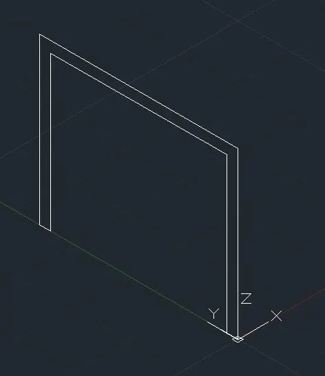
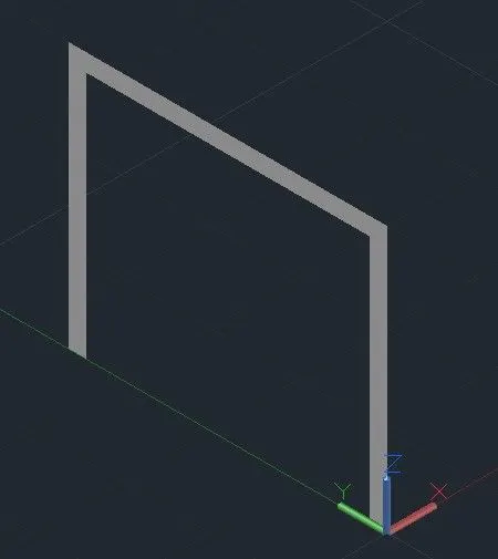
STEP 2) LINE CREATES FOR TABLE
- L enter for line command
- Specify the first point 0, 0, 0 enter
- Specify next point @0, 0, 2’6” enter
- Specify next point @0, 3, 0 enter
- Specify next point @0, 0, -2’6” enter
- Specify next point @0, -2”, 0 enter
- Specify next point @0,0,2’4” enter
- Specify next point @0, -2’8”, 0 enter
- Specify next point @0,0, -2’4” enter
- Specify next point @0,-2”,0 or C enter
STEP 3) REGION CREATES
- REG enter for region command
- Select object left click to select all lines, ENTER
- Change the visual style as REALISTIC from visual style control
STEP 4) EXTRUDE CREATES
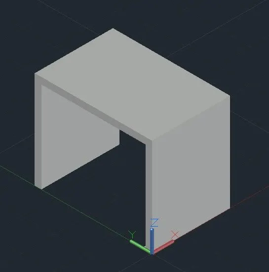
- EXT enter for extrude command
- Select object to Extrude click on the object at any point, enter
- Specify the height of extrusion 2’ enter
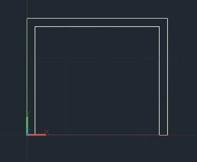
STEP 5) RECTANGLE CREATES IN Z PLANE OF THE OBJECT
- Change the view from view cube or 3D orbit
- Change the visual style as HIDDEN from visual style control
- Move the UCS icon and place in Z axis of the object
- Change the X-Y plane of the UCS icon to draw a rectangle
- Change the view and visual style
- Now extrude the rectangle inside 2” enter
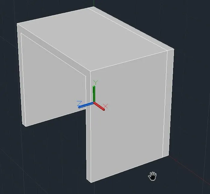
STEP 6) UNION THE CREATED OBJECT
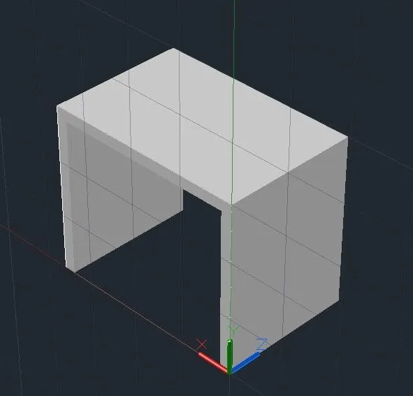
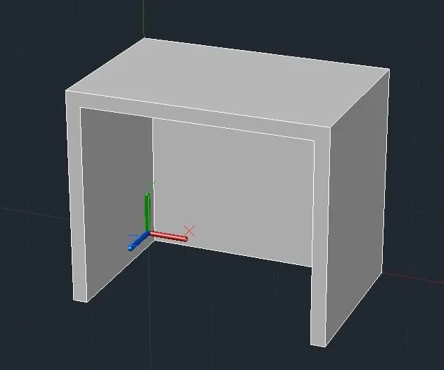
- UNI enter for the union command
- Select first object
- Select 2nd object, enter
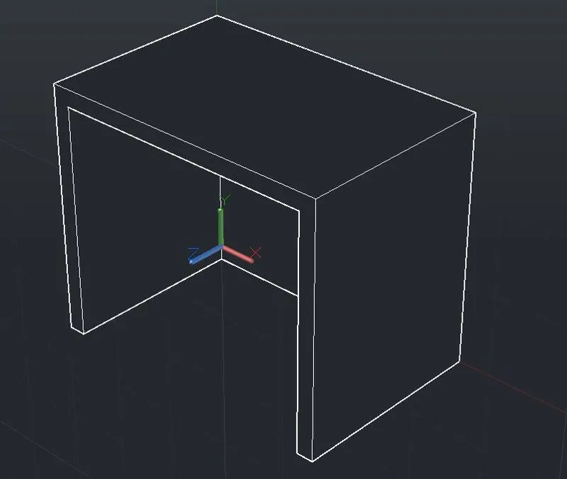
- Change the visual style as HIDDEN from visual style control
STEP 7) DIMENSION
- D enter for Dimension Style Manager, click on Modify
- Ensure unit format set as Engineering from primary unit tab
- Change over all scale as 10 from the fit tab OK, set current
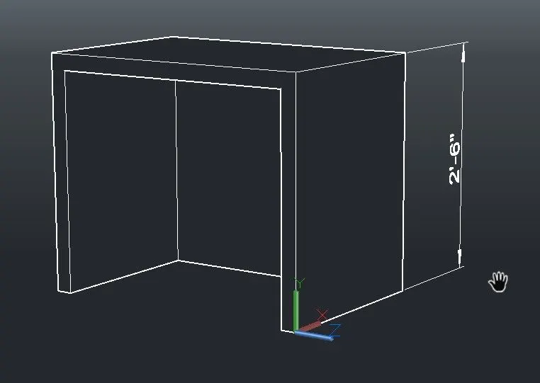
- To measure the vertical height of the table, place the UCS as X-Y position where the dimension required
- From Annotate ribbon go to dimension tool, select LINEAR
- Select first point and second point of the object to be measured
- Repeat for all the required object
RESULT:
Following above procedure and obtained the final result
2. Create the 3d Model of an Isolated footing as shown in Figure.
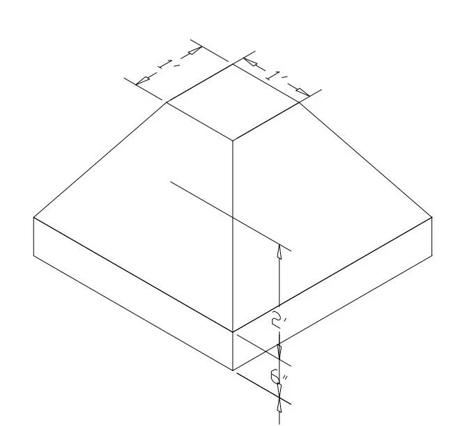
AIM: A 3D isolated footing is created in AutoCAD as given in figure
INTRODUCTION: The 3D model of isolated footing is created in 3D modeling workspace by using 2D and 3D tools. The procedure of the drawing is explained in detail with the figure and final result is given
PROCEDURE:
STEP 1) SELECTION OF DRAWING MODEL
- The isolated footing is created in above drawing file where the table is created
STEP 2) FOOTING CREATION
- Change the UCS as world
- Click on the TOP VIEW form view cube or view controls for 2D X-Y Plane
- REC enter for the rectangle command
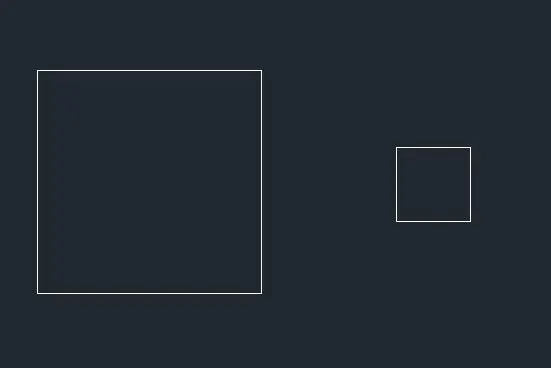
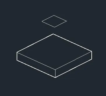
- Two rectangles of the size 3’x3’ and 1’x1’ is created
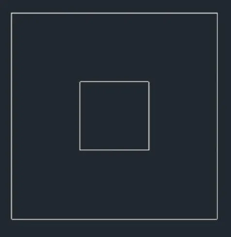
- Move the small rectangle from the center point and place above the center of the big rectangle
- Now move the small rectangle towards the z axis at 2’6” distance
- Change the view as isometric from view cube/view control or 3D orbit
- EXT enter for the extrude command
- Select the bottom rectangle enter
- Specify the height of extrusion 6” enter
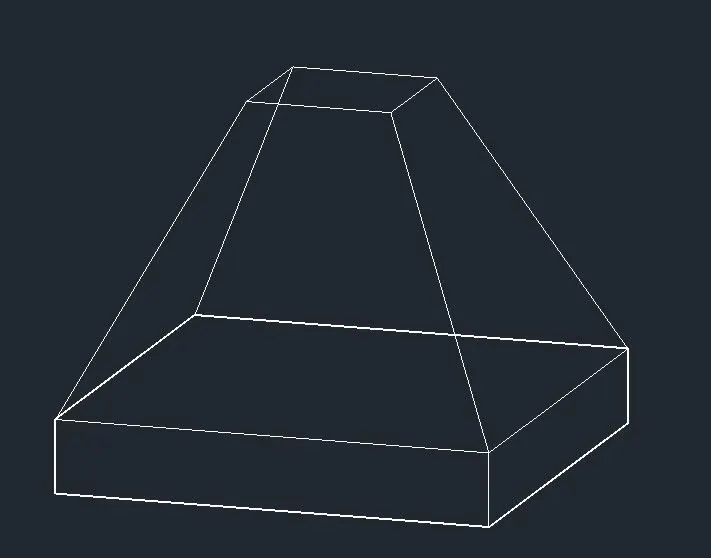
- Create lines connected to the corners of the top rectangle and cuboid
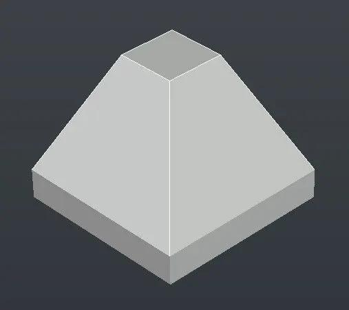
- Now create the 3DFACE for all tapered and top side
- Change the visual style as REALISTIC from visual style control

STEP 3) DIMENSION
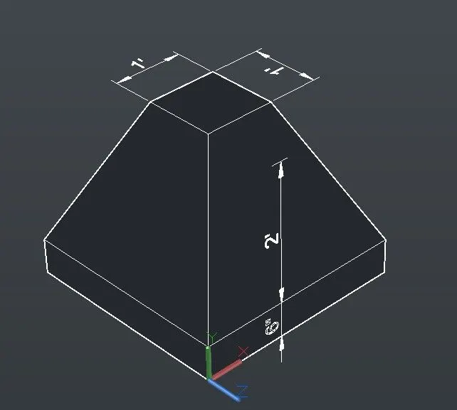
- Change the visual style as HIDDEN from visual style control
- Before measuring the any object, place the UCS on the plane and change the UCS direction as X-Y
- From Annotate ribbon go to dimension tool, select LINEAR
- Select first point and second point of the object to be measured
- Repeat for all the required object
RESULT:
Following above procedure and obtained the final result
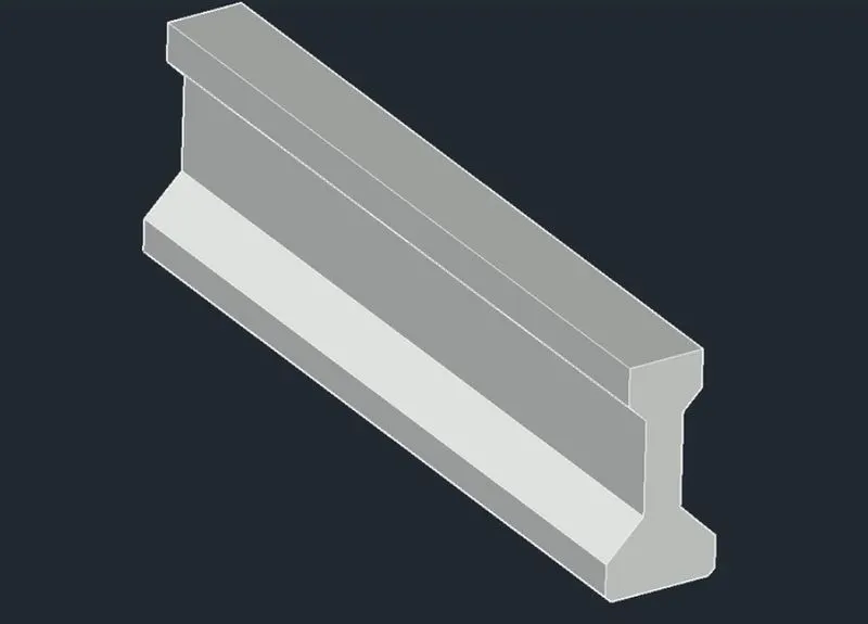
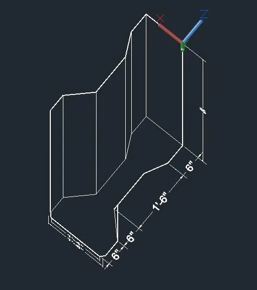
3. Create the 3D view of the AASTHO Type Girder.
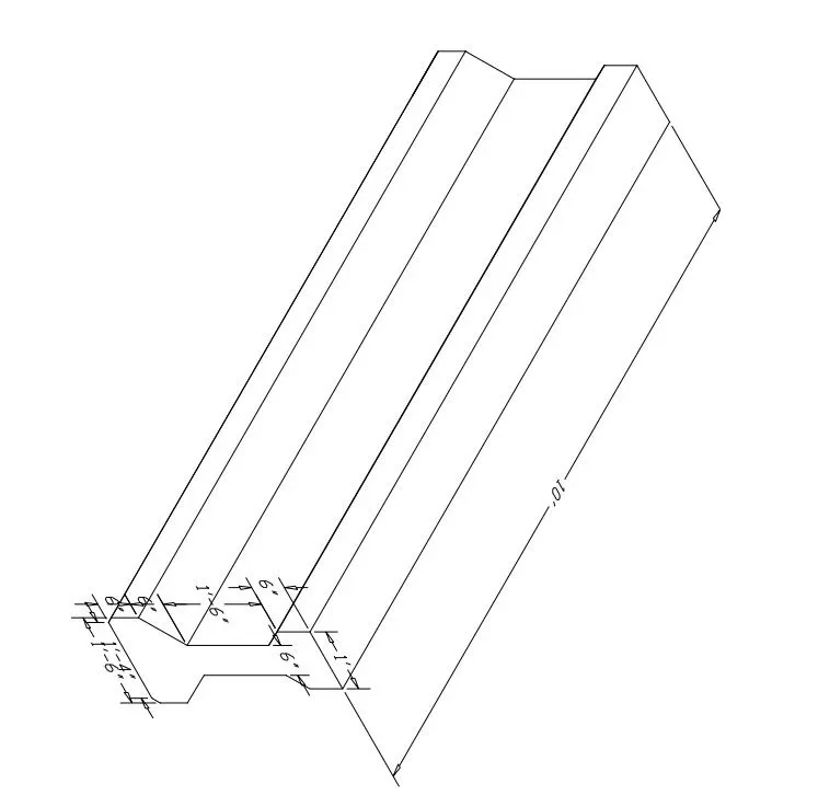
AIM: To create the 3D view of the AASTHO type girder as shown in the figure
INTRODUCTION: The 3D model of GIRDER is created in 3D modeling workspace by using 2D and 3D tools. The procedure of the drawing is explained in detail with the figure and final result is given
PROCEDURE:
STEP 1) SELECTION OF DRAWING MODEL
- The Girder is created in above drawing file
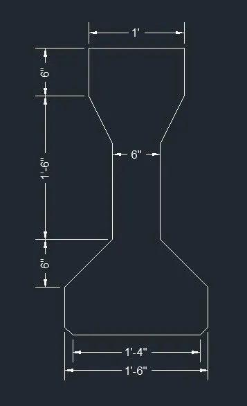
STEP 2) CREATE 2D PLAN OF GIRDER
- Change the UCS as world
- Click on the TOP VIEW form view cube or view controls for 2D X-Y Plane
- L enter for the line command
- Create a line of 1’6”
- Take the offset of this line at 6” distance for twice
- Again, offset the offseted line at 1’6” and 6” distance
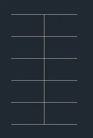
- Create a perpendicular line at the mid of the bottom and top horizontal line
- Take an offset of 6” from the both side of vertical line
- Trim and erase command used to remove unwanted line
- Take an offset of 3” from the both side of vertical line
- Trim and erase command used to remove unwanted line
- Draw a line as it as from the given drawing.
- CHA enter for chamfer command
- Select Distance then select first and second distance for chamfer distance as 1”
- Now select first line and second line for chamfer the corner
- Measure to ensure the 2D plan is accurate
STEP 3) CREATE GIRDER IN 3D
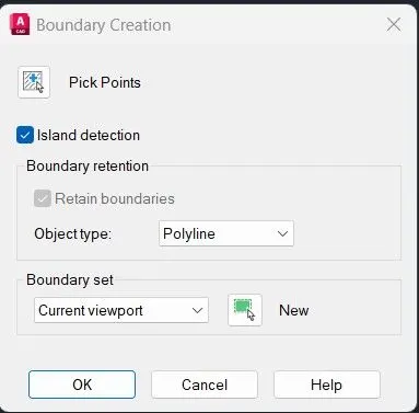
- BOUNDRY enter in command bar
- Click on Pick point in the popup
- Pick the internal point, place the cursor inside the object enter
- EXT enter in command bar for extrude
- Select object to extrude click on the object enter
- Specify the height of the extrusion 10’ enter
- Change view from view control or view cube or 3D orbit
- 3DROTATE command used to rotate at given position
- Change the visual style as REALISTIC from visual style control
STEP 4) DIMENSION
- Change the visual style as HIDDEN from visual style control
- Place the UCS on the plane and change the UCS direction as X-Y
- From Annotate ribbon go to dimension tool, select LINEAR
- Select first point and second point of the object to be measured
- Repeat for all the required object
RESULT:
Following above procedure and obtained the final result
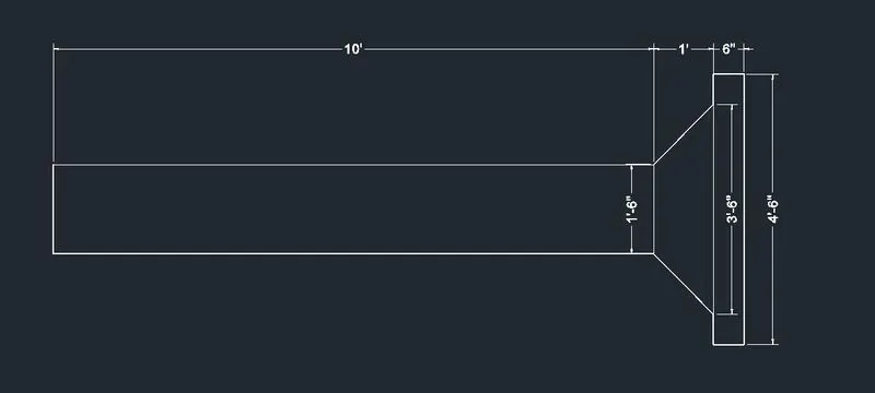
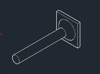
4. Create a 3d Model of a drop column with panel as shown in section and isometric view.
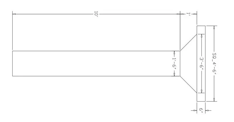
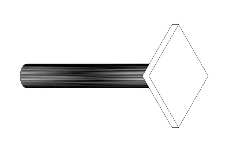
AIM: To create the 3D model of a drop column with panel in section and isometric view
INTRODUCTION: The 3D model of a drop column with panel is created in 3D Modeling workspace by using 2D and 3D tools. The procedure of the drawing is explained in detail with the figure and final result is given
PROCEDURE:
STEP 1) SELECTION OF DRAWING MODEL
- The column is created in above drawing file
STEP 2) CREATE DROP PANEL COLUMN
- Change the UCS as world
- Click on the TOP VIEW form view cube or view controls for 2D X-Y Plane
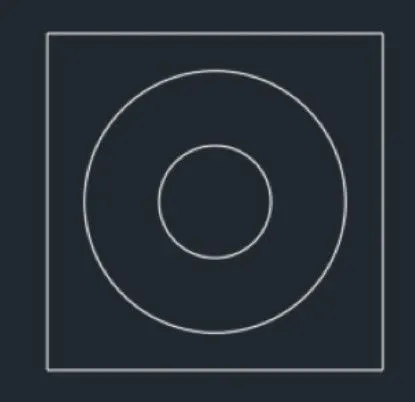
- Create a circle of diameter is 1’6”
- Again, circle created of diameter 3’6” at same center point of the 1st circle
- Create a rectangle of size 4’6”x 4’6”
- The center point for all object is same
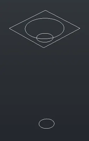
- Move the bigger circle and rectangle at 11’ distance towards z axis
- Shift + middle button of the mouse is used to 3D orbit the object
- COPY the smaller circle at 10’ distance towards the z axis
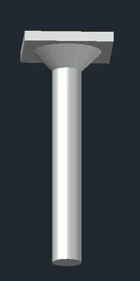
- LOFT command used to create tapered face between circles
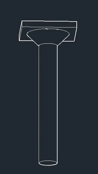
- EXTRUDE the upper rectangle towards the Z axis at the height of 6”
- Again, extrude the circle towards the Z axis at the height of 10’
- Change the visual style as REALISTIC and HIDDEN from visual style control
STEP 3) DIMENSION
- Change the visual style as 2DWIREFRAME from visual style control
- Place the UCS on the plane and change the UCS direction as X-Y
- From Annotate ribbon go to dimension tool, select LINEAR
- Select first point and second point of the object to be measured
- Repeat for all the required object
RESULT:
Following above procedure and obtained the final result
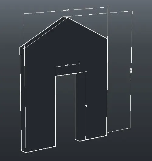
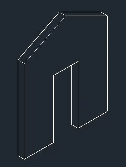
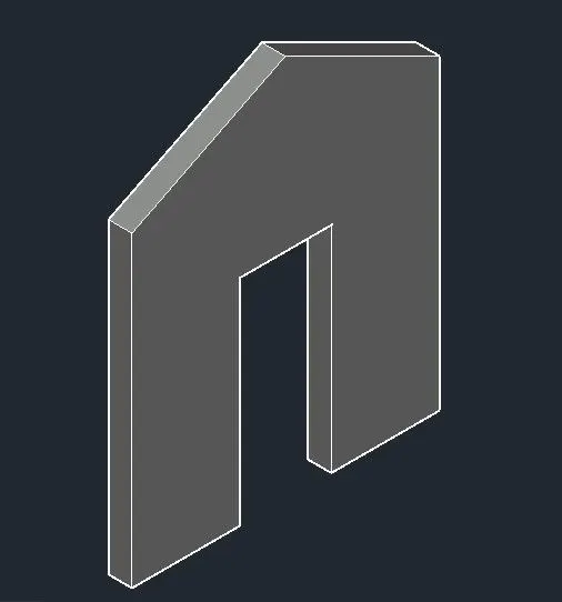
5. Create the 3d model of a wall as shown in Figure. Consider wall thickness as 9”.
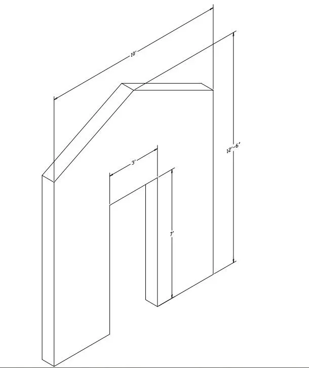
AIM: To create the 3D model of wall as shown in figure
INTRODUCTION: The 3D model of wall is created in 3D Modeling workspace by using 2D and 3D tools. The procedure of the drawing is explained in detail with the figure and final result is given
PROCEDURE:
STEP 1) SELECTION OF DRAWING MODEL
- The wall is created in above drawing file
STEP 2) CREATE WALL
- Change the UCS as world
- Click on the SW ISOMETRIC VIEW form view cube or view controls for 3D XYZ Plane
- L enter for line command
- Specify first point click on empty screen
- Specify next point @3’6”, 0, 0 enter
- Specify next point @0, 0, 7’ enter
- Specify next point @3’, 0, 0 enter
- Specify next point @0, 0, -7’ enter
- Specify next point @3’6”, 0, 0 enter
- Specify next point @0, 0, 10’ enter
- Specify next point @-10’, 0, 0 enter
- Specify next point @0, 0, -10’ enter, Esc
- Create a temporary line of 2’6” line at mid of top horizontal line and connect to left and right corners point of the wall
- Select to erase temporary lines
- REG enter for region
- Select whole object create above enter
- EXT enter for extrusion
- Select the object, enter
- Specify the height of extrusion 9”
- Change the visual style as SHADES OF GRAY from visual style control

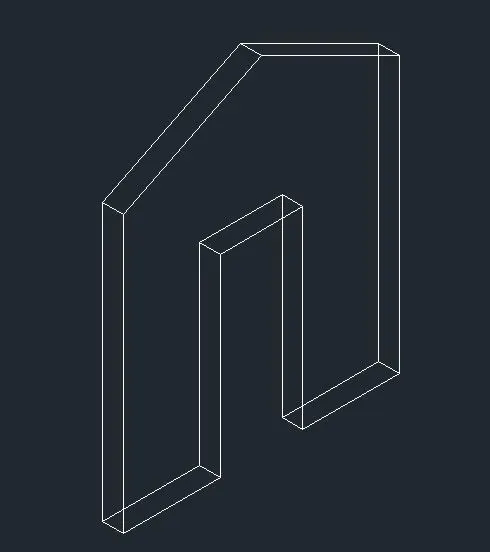
STEP 3) DIMENSION
- Change the visual style as HIDDEN from visual style control
- Place the UCS on the plane and change the UCS direction as X-Y
- From Annotate ribbon go to dimension tool, select LINEAR
- Select first point and second point of the object to be measured
- Repeat for all the required object
RESULT:
Following above procedure and obtained the final result