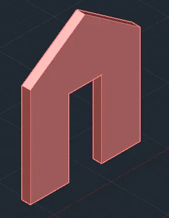
Creating various 3D Models like Furniture, Footing, Girder, Column drop with panel and Gable Wall in AutoCad
CREATING VARIOUS 3D MODELS LIKE FURNITURE, FOOTING, GRIDER, COLUMN DROP WITH PANEL AND GABLE WALL IN AUTOCAD
1. FURNITURE ELEMENT
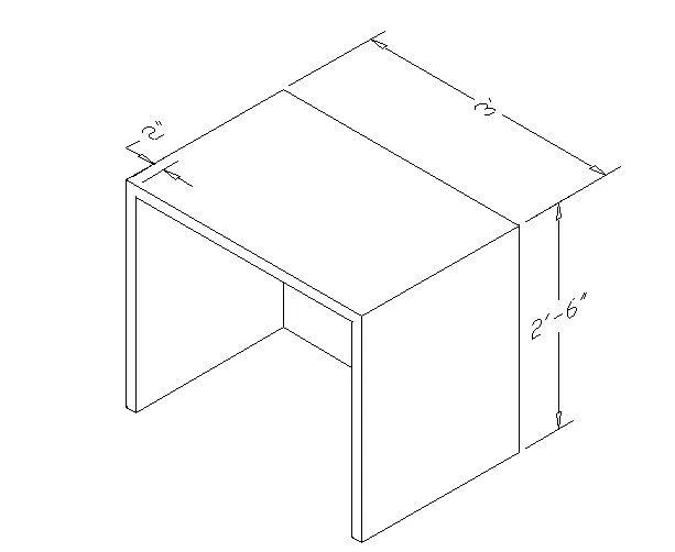
AIM-
TO DRAFT A FURNITURE ELEMENT USING AUTOCAD
INTODUCTION -
The main objective of this project is to understand about AutoCAD 3D.
AutoCAD is three-dimensional CAD software that is used commercially across the world. Developed by Autodesk in the year 1982. AutoCAD is also available as a mobile and web app, which is marketed as AutoCAD 360. AutoCAD offers an exclusive range of commands and functions both for 3D and 2D modeling and drawing with an amazing set of tools. 3D is all about the third Z coordinate. While working in 2D, the user only cares for the X and Y axis, and most of the time, coordinates are not used. Whereas, while working with 3D, the user uses all the coordinates, which can even make their work quite easier.
Today, technology has made it possible to link our imagination a bit closer to the reality, and it can be done by 3D modeling, printing, rendering and more. A huge number of software is available in the market that offers the users to bring their imagination into reality. Some of the software is freeware, while some are priced. With every update and with continuous new discoveries, people are more attracted to the technology offering them to make and create vivid designs. The need for 3D is a necessary part of the designing world. Without it, the design almost looks like a sketch.
TOOL USED FOR MAKING 3D MODEL
EXTRUDE-Creates a 3D solid from an object that encloses an area, or a 3D surface from an object with open ends. Objects can be extruded orthogonally from the plane of the source object, in a specified direction, or along a selected path. - HOME > MODELING > EXTRUDE
SWEEP - The 2D sub-object or object is swept along an open or closed path to create a 3D surface or solid using the sweep command. The object enclosing the area is swept to create a 3D solid or surface, but an open-ended object is swept to create only a 3D surface. - HOME > MODELING > SWEEP
UNION -The Union command is used to combine the selected 2D regions or 3D solids by the addition. The selected parts are combined to form a single region, surface, or solid. But, we are required to select the parts of the same object. We can select two or more parts to combine them into a single region, solid or surface.- Click Solids > Solid Editing > UNION
SUBTRACT - Creates as a new object by subtracting one overlapping region or 3D solid from another. With SUBTRACT, you can create a 3D solid by subtracting one set of existing 3D solids from another, overlapping set - Click Solids > Solid Editing > Subtract
PROCEDURE -
STEP 1 -
- Go to START MENU, and select AutoCAD.
- The User Interface of AutoCAD is OPEN.
- Click the start Drawing tab
- The workspace of AutoCad is open,
- Enter UNITS in the command box.
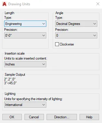
- Select ENGINEERING in TYPE, 0'-0" in PRECISION, and INCHES in UNITS TO SCALE INSERTED CONTENT.
- Select Angle type as DECIMAL DEGREE, and precision is 0 and direction are Anti-clockwise.
- Press OK.
STEP 2 -
- Set a LIMITS by command limits specify lower limit as 0,0 and upper limit as 100',100'
- Click on Customization at the botton of the Model space and click on workspace switching tab to show in the bar
- Now click on the Workspace switching and seleect a 3d Modeling
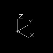
- and set a UCS
STEP 3 -
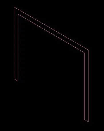
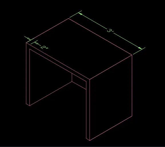
- Selet a Line command from the draw toolbar or type L and press ENTER in the command line
- Specify a first point as 0,0
- Specify the next coordinate point as @0,0,2'6".
- specify the next coordinate point as @3',0,0.
- Specify the next cordinate points as @0,0,-2'6"
- Specify the next coordinate point as @-2",0,0.
- Specify the next coordinate point as @0,0,2'4".
- Specify the next coordinate point as @-2'8",0,0
- Specify the next coordinate point as @0,0,-2'4".
- Specify the next coordinate point as @-2",0,0
STEP 4 -
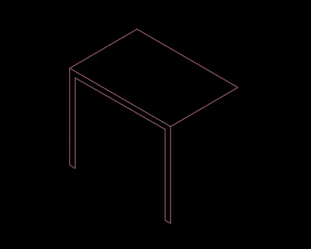
- Selet a Line command from the draw toolbar or type L and press ENTER in the command line
- Specify the first cordinate point as the top corner
- Specify the next coordinate point as @0,2',0.
- Specify the next coordinate point as @3',0,0
- Specify the next coordinate point as @0,-2',0.
STEP 5 -
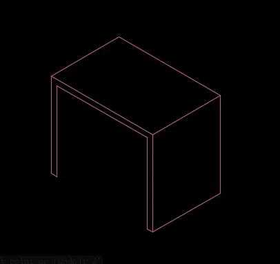
- Selet a Line command from the draw toolbar or type L and press ENTER in the command line
- Specify the first cordinate point as the top corner
- Specify the next coordinate point as @0,0,-2'6".
- Specify the next coordinate point as @0,-2',0.
STEP 6 -
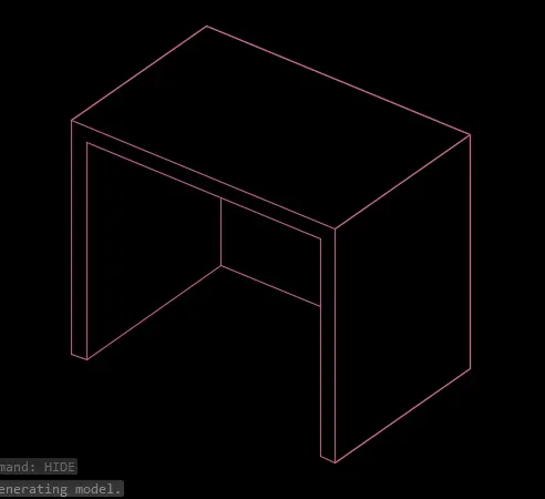
- Selet a Line command from the draw toolbar or type L and press ENTER in the command line
- Specify the first cordinate point as the bottom corner
- Specify the next coordinate point as @0,1'10",0.
- Specify the next coordinate point as @2'8",0,0.and from same point
- Specify the next coordinate point as @0,0,2'6".
RESULT -
2. ISOLATED FOOTING
AIM-
TO DRAFT A FISOLATED FOOTING USING AUTOCAD
INTODUCTION -
The main objective of this project is to understand about AutoCAD 3D.
AutoCAD is three-dimensional CAD software that is used commercially across the world. Developed by Autodesk in the year 1982. AutoCAD is also available as a mobile and web app, which is marketed as AutoCAD 360. AutoCAD offers an exclusive range of commands and functions both for 3D and 2D modeling and drawing with an amazing set of tools. 3D is all about the third Z coordinate. While working in 2D, the user only cares for the X and Y axis, and most of the time, coordinates are not used. Whereas, while working with 3D, the user uses all the coordinates, which can even make their work quite easier.
Today, technology has made it possible to link our imagination a bit closer to the reality, and it can be done by 3D modeling, printing, rendering and more. A huge number of software is available in the market that offers the users to bring their imagination into reality. Some of the software is freeware, while some are priced. With every update and with continuous new discoveries, people are more attracted to the technology offering them to make and create vivid designs. The need for 3D is a necessary part of the designing world. Without it, the design almost looks like a sketch.
TOOL USED FOR MAKING 3D MODEL
EXTRUDE-Creates a 3D solid from an object that encloses an area, or a 3D surface from an object with open ends. Objects can be extruded orthogonally from the plane of the source object, in a specified direction, or along a selected path. - HOME > MODELING > EXTRUDE
SWEEP - The 2D sub-object or object is swept along an open or closed path to create a 3D surface or solid using the sweep command. The object enclosing the area is swept to create a 3D solid or surface, but an open-ended object is swept to create only a 3D surface. - HOME > MODELING > SWEEP
UNION -The Union command is used to combine the selected 2D regions or 3D solids by the addition. The selected parts are combined to form a single region, surface, or solid. But, we are required to select the parts of the same object. We can select two or more parts to combine them into a single region, solid or surface.- Click Solids > Solid Editing > UNION
SUBTRACT - Creates as a new object by subtracting one overlapping region or 3D solid from another. With SUBTRACT, you can create a 3D solid by subtracting one set of existing 3D solids from another, overlapping set - Click Solids > Solid Editing > Subtract
PROCEDURE -
STEP 1 -
- Go to START MENU, and select AutoCAD.
- The User Interface of AutoCAD is OPEN.
- Click the start Drawing tab
- The workspace of AutoCad is open,
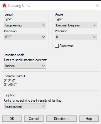
- Enter UNITS in the command box.
- Select ENGINEERING in TYPE, 0'-0" in PRECISION, and INCHES in UNITS TO SCALE INSERTED CONTENT.
- Select Angle type as DECIMAL DEGREE, and precision is 0 and direction are Anti-clockwise.
- Press OK.
STEP 2 -
- Set a LIMITS by command limits specify lower limit as 0,0 and upper limit as 100',100'
- Click on Customization at the botton of the Model space and click on workspace switching tab to show in the bar
- Now click on the Workspace switching and seleect a 3d Modeling
- and set a UCS
STEP 3 -
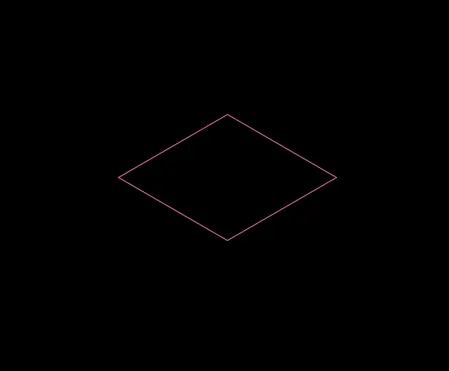
- Select a rectangle command from thee draw tool or type REC and press ENTER in the command line
- Click on DIMENSION in the command line
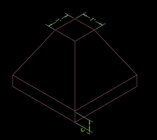
- Specify the length of the rectangle as 1'
- Specify the width of rectangle as 1'
- Click on th screen as a direction of the rectangle
- press ESC.
STEP 4 -
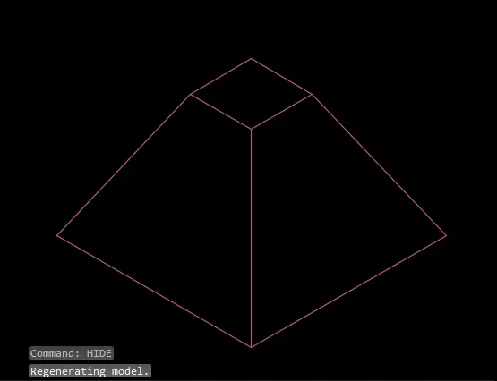
- Select the rectangle and type REGION and press ENTER for create a region
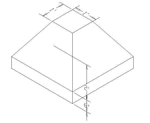
- Select a EXTRUDE command from the draw modeling tool or type EXTRUDE and press ENTER in the command line.
- Click on taper angle in the command line
- And specify the taper angle as b and press enter
- Specify the height of depth as 2'and press enter
STEP 5 -
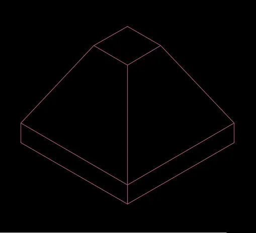
- Select a pushpull tool from the home modeling and click on bottom of the rectangle and
- specify the width as 6"
RESULT -
3. GRIDER
AIM-
TO DRAFT A GRIDER USING AUTOCAD
INTODUCTION -
The main objective of this project is to understand about AutoCAD 3D.
AutoCAD is three-dimensional CAD software that is used commercially across the world. Developed by Autodesk in the year 1982. AutoCAD is also available as a mobile and web app, which is marketed as AutoCAD 360. AutoCAD offers an exclusive range of commands and functions both for 3D and 2D modeling and drawing with an amazing set of tools. 3D is all about the third Z coordinate. While working in 2D, the user only cares for the X and Y axis, and most of the time, coordinates are not used. Whereas, while working with 3D, the user uses all the coordinates, which can even make their work quite easier.
Today, technology has made it possible to link our imagination a bit closer to the reality, and it can be done by 3D modeling, printing, rendering and more. A huge number of software is available in the market that offers the users to bring their imagination into reality. Some of the software is freeware, while some are priced. With every update and with continuous new discoveries, people are more attracted to the technology offering them to make and create vivid designs. The need for 3D is a necessary part of the designing world. Without it, the design almost looks like a sketch.
TOOL USED FOR MAKING 3D MODEL
EXTRUDE-Creates a 3D solid from an object that encloses an area, or a 3D surface from an object with open ends. Objects can be extruded orthogonally from the plane of the source object, in a specified direction, or along a selected path. - HOME > MODELING > EXTRUDE
SWEEP - The 2D sub-object or object is swept along an open or closed path to create a 3D surface or solid using the sweep command. The object enclosing the area is swept to create a 3D solid or surface, but an open-ended object is swept to create only a 3D surface. - HOME > MODELING > SWEEP
UNION -The Union command is used to combine the selected 2D regions or 3D solids by the addition. The selected parts are combined to form a single region, surface, or solid. But, we are required to select the parts of the same object. We can select two or more parts to combine them into a single region, solid or surface.- Click Solids > Solid Editing > UNION
SUBTRACT - Creates as a new object by subtracting one overlapping region or 3D solid from another. With SUBTRACT, you can create a 3D solid by subtracting one set of existing 3D solids from another, overlapping set - Click Solids > Solid Editing > Subtract
PROCEDURE -
STEP 1 -
- Go to START MENU, and select AutoCAD.
- The User Interface of AutoCAD is OPEN.
- Click the start Drawing tab
- The workspace of AutoCad is open,
- Enter UNITS in the command box.
- Select ENGINEERING in TYPE, 0'-0" in PRECISION, and INCHES in UNITS TO SCALE INSERTED CONTENT.
- Select Angle type as DECIMAL DEGREE, and precision is 0 and direction are Anti-clockwise.
- Press OK.
STEP 2 -
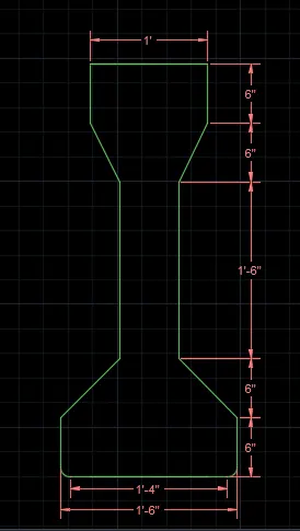
- Selet a Line command from the draw toolbar or type L and press ENTER in the command line
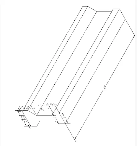
- Specify a first point as 0,0
- Specify the next coordinate point as @1'6",0
- specify the next coordinate point as @0,6"
- Specify the next cordinate points as @-3",6"
- Specify the next coordinate point as @,0,1'6''.
- Specify the next coordinate point as @3",6".
- Specify the next coordinate point as @0,6"
- Specify the next coordinate point as @-1',0
- Select a MIRROR command and select a complete object
- Specify the base point as mid point of 1' mirrior it and press enter
STEP 3 -
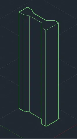
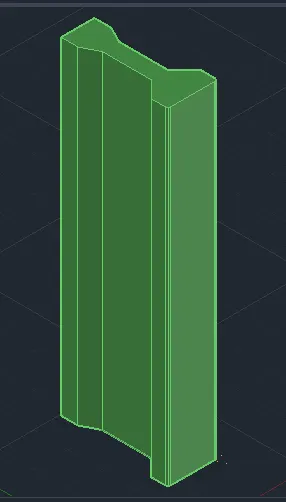
- Select the complete object and press REGION and enter
- Select a EXTRUDE command from the draw modeling tool or type EXTRUDE and press ENTER in the command line.
- Specify the height as 10'
RESULT -
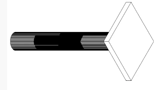
4. COLUMN WITH PANEL
AIM-
TO DRAFT A COLUMN WITH PANEL USING AUTOCAD
INTODUCTION -
The main objective of this project is to understand about AutoCAD 3D.
AutoCAD is three-dimensional CAD software that is used commercially across the world. Developed by Autodesk in the year 1982. AutoCAD is also available as a mobile and web app, which is marketed as AutoCAD 360. AutoCAD offers an exclusive range of commands and functions both for 3D and 2D modeling and drawing with an amazing set of tools. 3D is all about the third Z coordinate. While working in 2D, the user only cares for the X and Y axis, and most of the time, coordinates are not used. Whereas, while working with 3D, the user uses all the coordinates, which can even make their work quite easier.
Today, technology has made it possible to link our imagination a bit closer to the reality, and it can be done by 3D modeling, printing, rendering and more. A huge number of software is available in the market that offers the users to bring their imagination into reality. Some of the software is freeware, while some are priced. With every update and with continuous new discoveries, people are more attracted to the technology offering them to make and create vivid designs. The need for 3D is a necessary part of the designing world. Without it, the design almost looks like a sketch.
TOOL USED FOR MAKING 3D MODEL
EXTRUDE-Creates a 3D solid from an object that encloses an area, or a 3D surface from an object with open ends. Objects can be extruded orthogonally from the plane of the source object, in a specified direction, or along a selected path. - HOME > MODELING > EXTRUDE
SWEEP - The 2D sub-object or object is swept along an open or closed path to create a 3D surface or solid using the sweep command. The object enclosing the area is swept to create a 3D solid or surface, but an open-ended object is swept to create only a 3D surface. - HOME > MODELING > SWEEP
UNION -The Union command is used to combine the selected 2D regions or 3D solids by the addition. The selected parts are combined to form a single region, surface, or solid. But, we are required to select the parts of the same object. We can select two or more parts to combine them into a single region, solid or surface.- Click Solids > Solid Editing > UNION
SUBTRACT - Creates as a new object by subtracting one overlapping region or 3D solid from another. With SUBTRACT, you can create a 3D solid by subtracting one set of existing 3D solids from another, overlapping set - Click Solids > Solid Editing > Subtract
PROCEDURE -
STEP 1 -
- Go to START MENU, and select AutoCAD.
- The User Interface of AutoCAD is OPEN.
- Click the start Drawing tab
- The workspace of AutoCad is open,
- Enter UNITS in the command box.
- Select ENGINEERING in TYPE, 0'-0" in PRECISION, and INCHES in UNITS TO SCALE INSERTED CONTENT.
- Select Angle type as DECIMAL DEGREE, and precision is 0 and direction are Anti-clockwise.
- Press OK.
STEP 2 -
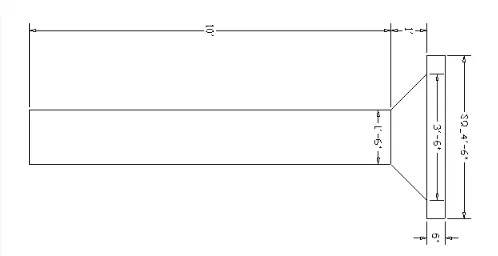
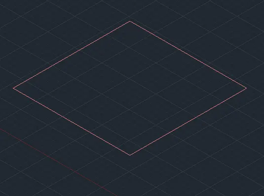
- Select a rectangle command from thee draw tool or type REC and press ENTER in the command line
- Click on DIMENSION in the command line
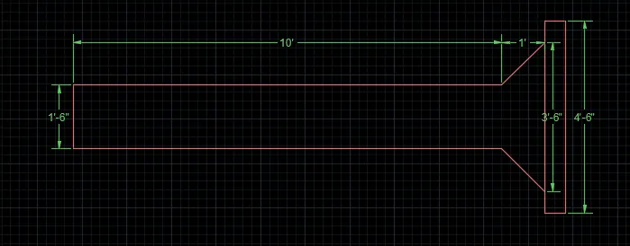
- Specify the length of the rectangle as 4'6"
- Specify the width of rectangle as 4'6"
- Click on th screen as a direction of the rectangle
- press ESC.
STEP 3 -
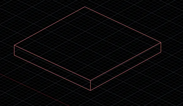
- Select a rectangle and press REGION to make a region
- Select a EXTRUDE command from the draw modeling tool or type EXTRUDE and press ENTER in the command line.
- Specify the height as 6"
STEP 4 -
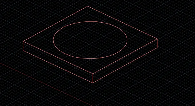
- Select a CIRCLE command from the draw pannel or type C and press ENTER
- Specify a circle point as geometric center and
- Specify the diameter of circle s 3'6"
STEP 5 -
- Select a CIRCLE command from the draw pannel or type C and press ENTER
- Specify a circle point as geometric center and
- Specify the diameter of circle s 1'6"
- Select a MOVE command from the draw panel or type M and press ENTER
- Specify base point as center of a circle
- and enter the new cordinates as 0,0,1'
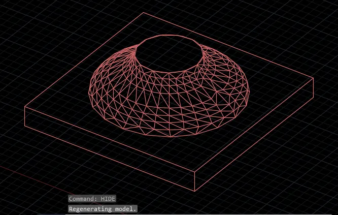
- Select a LOFT command from the draw modeling tool or type LOFT and press ENTER in the command line.
- Select both the circle and press enter.
STEP 6 -
- Create a region on the top of the circle and
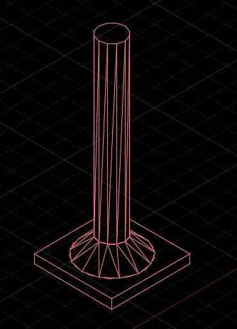
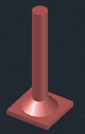
- Select a EXTRUDE command from the draw modeling tool or type EXTRUDE and press ENTER in the command line.
- Specify the height as 10'
RESULT -
5. WALL
AIM-
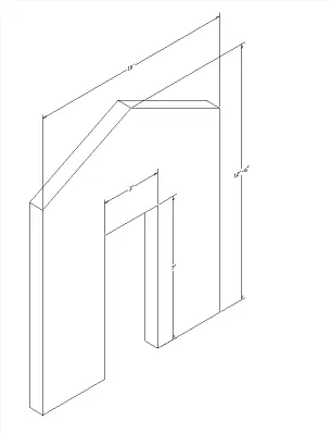
TO DRAFT A WALL USING AUTOCAD
INTODUCTION -
The main objective of this project is to understand about AutoCAD 3D.
AutoCAD is three-dimensional CAD software that is used commercially across the world. Developed by Autodesk in the year 1982. AutoCAD is also available as a mobile and web app, which is marketed as AutoCAD 360. AutoCAD offers an exclusive range of commands and functions both for 3D and 2D modeling and drawing with an amazing set of tools. 3D is all about the third Z coordinate. While working in 2D, the user only cares for the X and Y axis, and most of the time, coordinates are not used. Whereas, while working with 3D, the user uses all the coordinates, which can even make their work quite easier.
Today, technology has made it possible to link our imagination a bit closer to the reality, and it can be done by 3D modeling, printing, rendering and more. A huge number of software is available in the market that offers the users to bring their imagination into reality. Some of the software is freeware, while some are priced. With every update and with continuous new discoveries, people are more attracted to the technology offering them to make and create vivid designs. The need for 3D is a necessary part of the designing world. Without it, the design almost looks like a sketch.
TOOL USED FOR MAKING 3D MODEL
EXTRUDE-Creates a 3D solid from an object that encloses an area, or a 3D surface from an object with open ends. Objects can be extruded orthogonally from the plane of the source object, in a specified direction, or along a selected path. - HOME > MODELING > EXTRUDE
SWEEP - The 2D sub-object or object is swept along an open or closed path to create a 3D surface or solid using the sweep command. The object enclosing the area is swept to create a 3D solid or surface, but an open-ended object is swept to create only a 3D surface. - HOME > MODELING > SWEEP
UNION -The Union command is used to combine the selected 2D regions or 3D solids by the addition. The selected parts are combined to form a single region, surface, or solid. But, we are required to select the parts of the same object. We can select two or more parts to combine them into a single region, solid or surface.- Click Solids > Solid Editing > UNION
SUBTRACT - Creates as a new object by subtracting one overlapping region or 3D solid from another. With SUBTRACT, you can create a 3D solid by subtracting one set of existing 3D solids from another, overlapping set - Click Solids > Solid Editing > Subtract
PROCEDURE -
STEP 1 -
- Go to START MENU, and select AutoCAD.
- The User Interface of AutoCAD is OPEN.
- Click the start Drawing tab
- The workspace of AutoCad is open,
- Enter UNITS in the command box.
- Select ENGINEERING in TYPE, 0'-0" in PRECISION, and INCHES in UNITS TO SCALE INSERTED CONTENT.
- Select Angle type as DECIMAL DEGREE, and precision is 0 and direction are Anti-clockwise.
- Press OK.
STEP 2 -
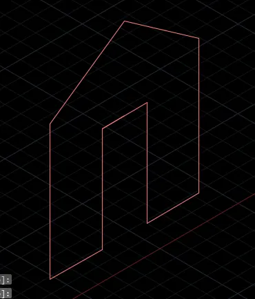
- Selet a Line command from the draw toolbar or type L and press ENTER in the command line
- Specify a first point as 0,0
- Specify the next coordinate point as @0,0,9'
- specify the next coordinate point as @5',0,3'6"
- Specify the next cordinate points as @5',0,-3'6"
- Specify the next coordinate point as @0,0,-9'
- Specify the next coordinate point as @-41",0,0
- Specify the next coordinate point as @0,0,7'
- Specify the next coordinate point as @-3',0,0.
- Specify the next coordinate point as @0,0,-7'
- Specify the next coordinate point as @-41",0,0
STEP 3 -
- Select a rectangle and press REGION to make a region
- Select a EXTRUDE command from the draw modeling tool or type EXTRUDE and press ENTER in the command line.
- Specify the height as 9"

RESULT -