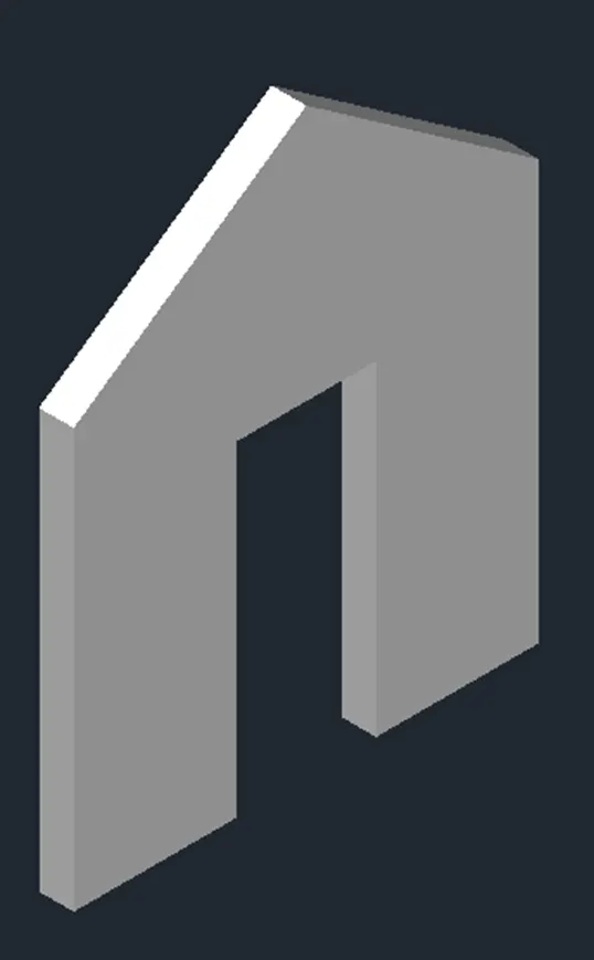
Creating various 3D Models like Furniture, Footing, Girder, Column drop with panel and Gable Wall in AutoCad
- 3D MODEL OF A FURNITURE:
AIM:
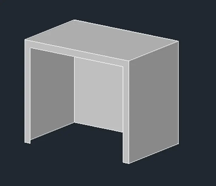
To create 3D model of a furniture as shown below using AutoCAD.
INTRODUCTION:
The following commands and tools are used in this Auto CAD drawing,
- Line: It helps to create a line between two points
- Rectangle: It helps to create a four-sided geometry with a desired length and width.
- Offset: It helps to offset an object at a particular distance.
- Move: It helps to move an already existing object from one point to the other by picking a base point.
- Copy: It helps to copy an already existing object from one point to the other by picking a base point.
- Trim: It helps to trim off the extra lines or objects of a selected object which is created while using other tools.
- Erase: It helps to erase a selected object.
- 3DFace: It helps to create 2D wireframe into 3DFace
- 3DOrbit: It helps to view the 3Dobject in all direction.
PROCEDURE:
- In the status bar set the setting as 3D modeling
- Enter Units and select type as Engineering and units as Inches
- Enter LIMMAX as 50’
- Enter rec and create 2’x3’ rectangle
- Using line command create a line of height 2’6”
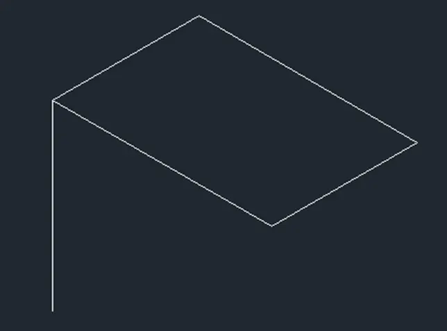
- Enter co and copy the rectangle on top of the line
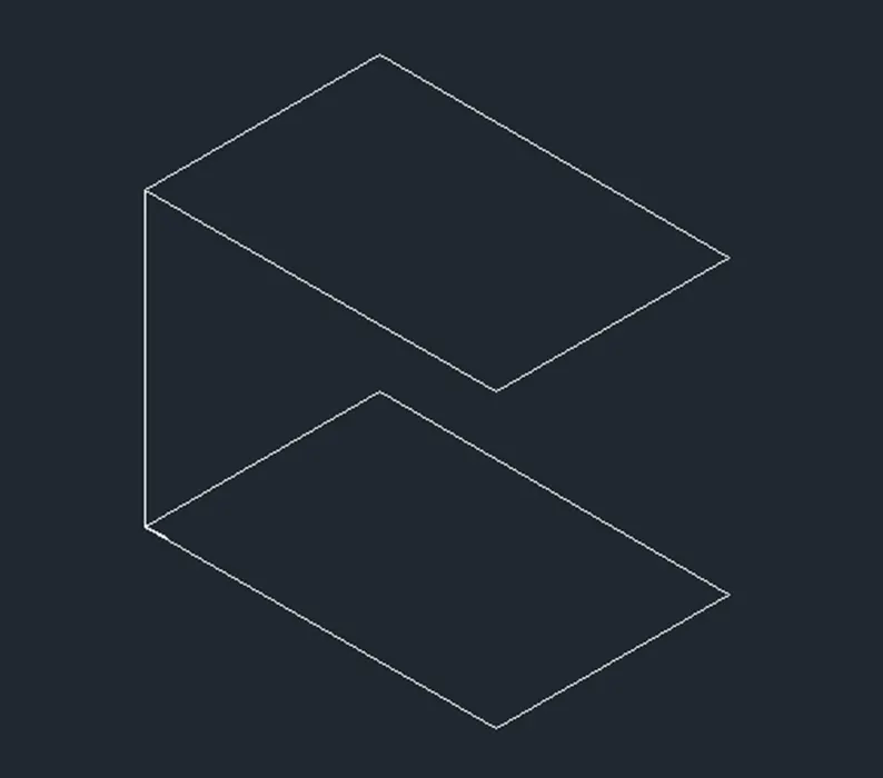
- Using line command join all the corner of the line
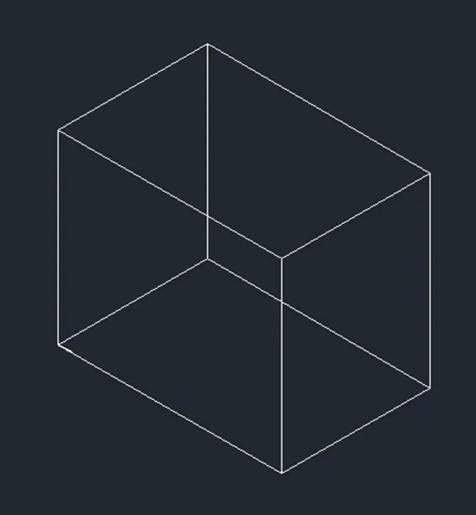
- In the front view create inner lines of 2” on 3 sides
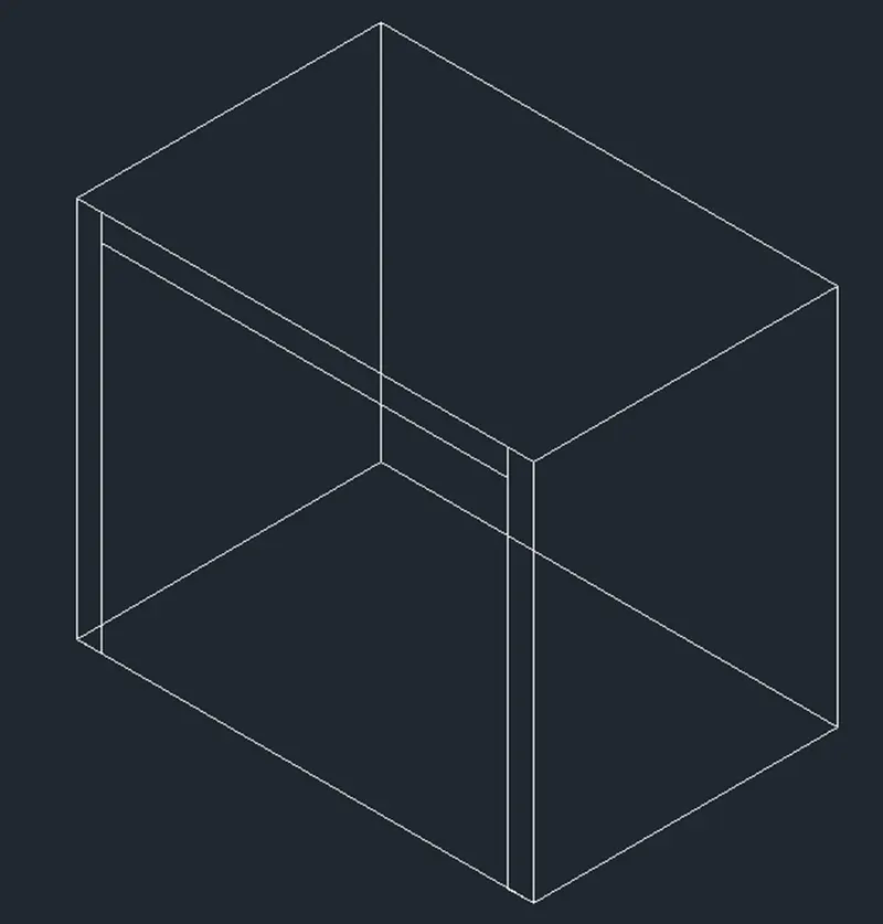
- Erase the remaining line
- Use 3DFace to convert in to 3D object
- Change the view to shaded
RESULT:
The following result is obtained by the above steps
- 3D MODEL OF AN ISOLATED FOOTING:
AIM:
To create 3D model of an isolated footing as shown below using AutoCAD.
INTRODUCTION:
The following commands and tools are used in this Auto CAD drawing,
- Line: It helps to create a line between two points
- Rectangle: It helps to create a four-sided geometry with a desired length and width.
- Offset: It helps to offset an object at a particular distance.
- Move: It helps to move an already existing object from one point to the other by picking a base point.
- Copy: It helps to copy an already existing object from one point to the other by picking a base point.
- Trim: It helps to trim off the extra lines or objects of a selected object which is created while using other tools.
- Erase: It helps to erase a selected object.
- 3DFace: It helps to create 2D wireframe into 3DFace
- 3DOrbit: It helps to view the 3Dobject in all direction.
- Loft: It helps to create 3D solids in the space between several layers
- Press and pull: It helps to press and pull the boundary area
PROCEDURE:
- In the status bar set the setting as 3D modeling
- Enter Units and select type as Engineering and units as Inches
- Enter LIMMAX as 50’
- Enter rec and create 3’x3’ rectangle
- Pick the center point and draw line of dimension 2’ on top
- By picking the end point draw a rec of dimension 1’x1’
- Enter move to move the smaller rectangle to the center
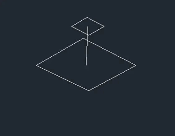
- Select loft command and select the loft order
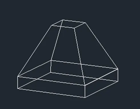
- Select the bottom boundary area and select press and pull and give dimension as 6”
- RESULT:
- The following result is obtained by the above steps
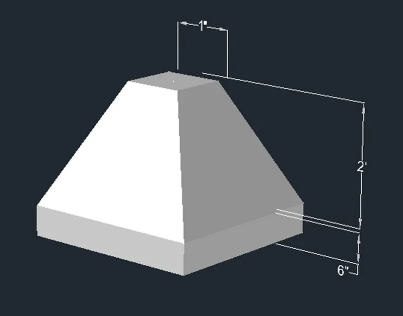
- 3D VIEW OF THE AASTHO TYPE GIRDER:
AIM:
To create 3d view of the aastho type girder as shown below using AutoCAD.
INTRODUCTION:
The following commands and tools are used in this Auto CAD drawing,
- Line: It helps to create a line between two points
- Rectangle: It helps to create a four-sided geometry with a desired length and width.
- Offset: It helps to offset an object at a particular distance.
- Move: It helps to move an already existing object from one point to the other by picking a base point.
- Copy: It helps to copy an already existing object from one point to the other by picking a base point.
- Trim: It helps to trim off the extra lines or objects of a selected object which is created while using other tools.
- Erase: It helps to erase a selected object.
- 3DFace: It helps to create 2D wireframe into 3DFace
- 3DOrbit: It helps to view the 3Dobject in all direction.
- Loft: It helps to create 3D solids in the space between several layers
- Press and pull: It helps to press and pull the boundary area
- Boundary: It helps to create a region from a 2D frame
PROCEDURE:
- In the status bar set the setting as 3D modeling
- Enter Units and select type as Engineering and units as Inches
- Enter LIMMAX as 50’
- Select line command and draw horizontal line of 6”
- Vertical line of 6”
- Switch on polar tracking and with angle 30 and length 3” create a line
- Move the cursor down and draw a line of 1’3” dimension
- By Polar tracking, with angle 150 and length 6” create a line
- Move the cursor to the right and draw a line of 9” dimension
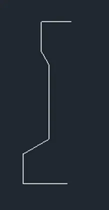
- Select mirror command and create a mirror image
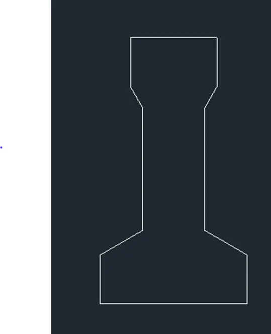
- Use chamfer of first line length as 1” and second line length as1” at the bottom
- Enter boundary and pick a point inside to create a region
- Select extrude and give length as 10’
- RESULT:
- The following result is obtained by the above steps
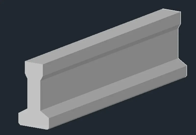
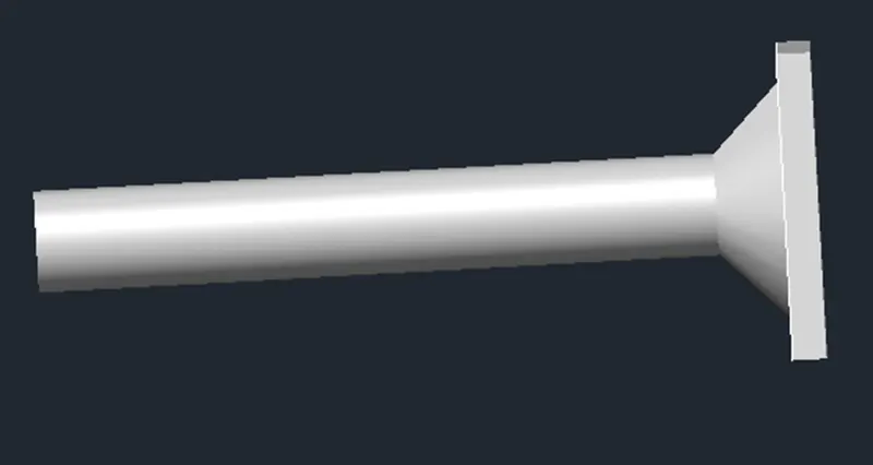
- 3D MODEL OF A DROP COLUMN WITH PANEL:
AIM:
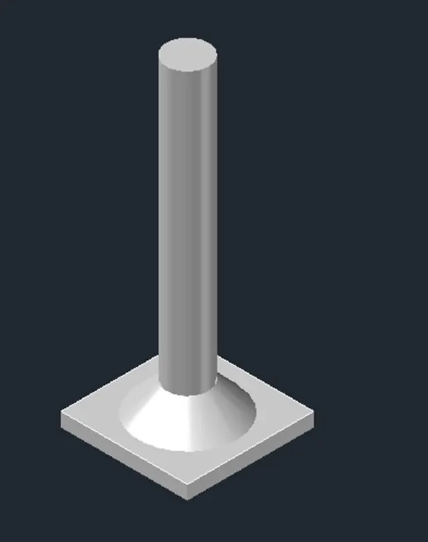
To create 3D Model of a drop column with panel as shown below using AutoCAD.
INTRODUCTION:
The following commands and tools are used in this Auto CAD drawing,
- Line: It helps to create a line between two points
- Rectangle: It helps to create a four-sided geometry with a desired length and width.
- Offset: It helps to offset an object at a particular distance.
- Move: It helps to move an already existing object from one point to the other by picking a base point.
- Copy: It helps to copy an already existing object from one point to the other by picking a base point.
- Trim: It helps to trim off the extra lines or objects of a selected object which is created while using other tools.
- Erase: It helps to erase a selected object.
- 3DFace: It helps to create 2D wireframe into 3DFace
- 3DOrbit: It helps to view the 3Dobject in all direction.
- Loft: It helps to create 3D solids in the space between several layers
- Press and pull: It helps to press and pull the boundary area
- Boundary: It helps to create a region from a 2D frame
PROCEDURE:
- In the status bar set the setting as 3D modeling
- Enter Units and select type as Engineering and units as Inches
- Enter LIMMAX as 50’
- Enter rec and create a rectangle of 4’6” dimension
- Pick up the center point and enter c and create a circle of diameter3’6”
- Enter l and with the same center create a line of 1”
- Create a circle of diameter 1’6” at the end point of the line
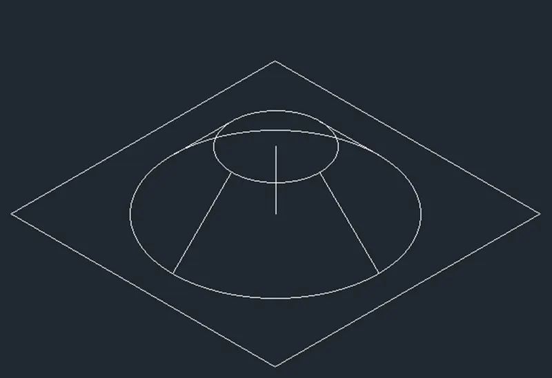
- Select loft command select 2 circles
- Create a circle of diameter of 1’6” on top
- Select extrude and give height as 10’
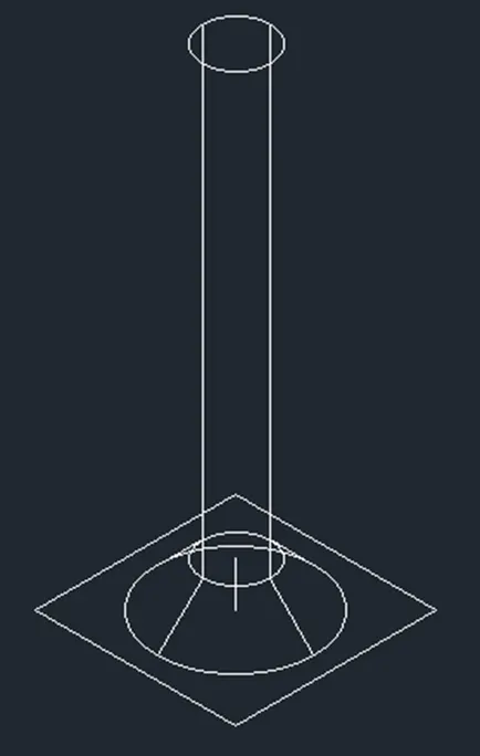
- Select press and pull and select the rectangle and give height as 6”
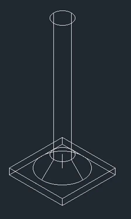
- RESULT:
- The following result is obtained by the above steps
- 3D MODEL OF A WALL:
AIM:
To create 3D model of a wall as shown below using AutoCAD.
INTRODUCTION:
The following commands and tools are used in this Auto CAD drawing,
- Line: It helps to create a line between two points
- Rectangle: It helps to create a four-sided geometry with a desired length and width.
- Offset: It helps to offset an object at a particular distance.
- Move: It helps to move an already existing object from one point to the other by picking a base point.
- Copy: It helps to copy an already existing object from one point to the other by picking a base point.
- Trim: It helps to trim off the extra lines or objects of a selected object which is created while using other tools.
- Erase: It helps to erase a selected object.
- 3DFace: It helps to create 2D wireframe into 3DFace
- 3DOrbit: It helps to view the 3Dobject in all direction.
- Loft: It helps to create 3D solids in the space between several layers
- Press and pull: It helps to press and pull the boundary area
- Boundary: It helps to create a region from a 2D frame
- Region: It helps to create a surface of a 2D wireframe
PROCEDURE:
- In the status bar set the setting as 3D modeling
- Enter Units and select type as Engineering and units as Inches
- Enter LIMMAX as 50’
- Using line command draw the below diagram with the given dimension
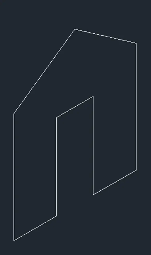
- Create region out of it using region command by selecting it as whole
- Enter Extrude and give wall thickness as 9”
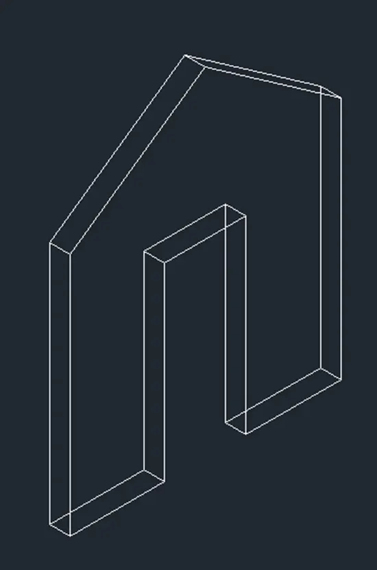
- RESULT:
- The following result is obtained by the above steps