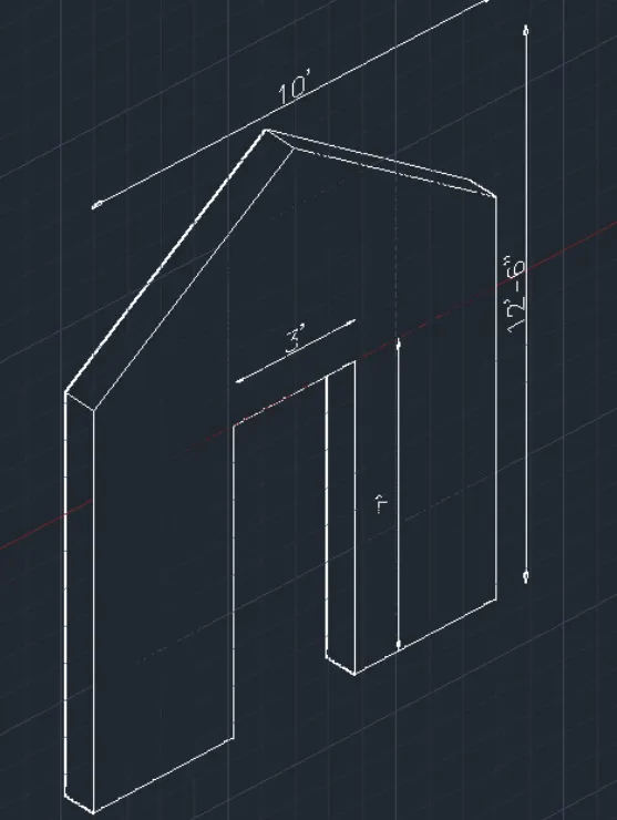
Creating various 3D Models like Furniture, Footing, Girder, Column drop with panel and Gable Wall in AutoCad
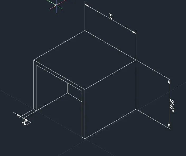
1. AIM: Create a 3D Furniture element as shown in the Figure. Assume dimensions which are missing
PROCEDURE:
1. Open the autocad and go to the 3d modeling in the settings and change the work space to 3d modeling
2.now the unit as the architectural feet and inches
3.set the limits
step1
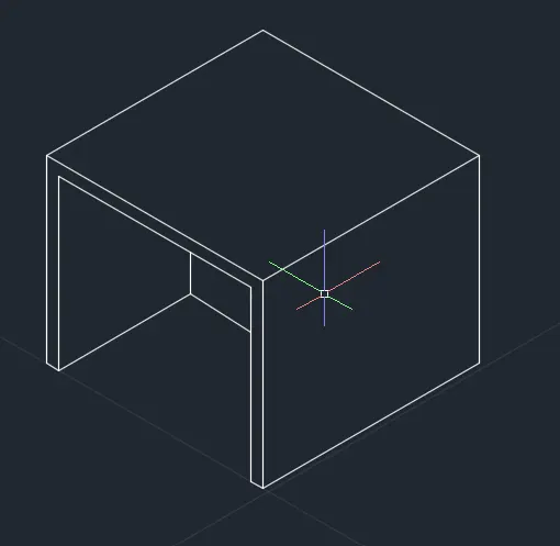
step2:
RESULT:
2.AIM:
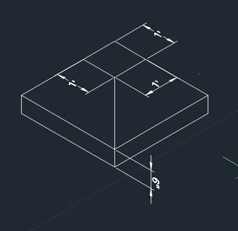
Create the 3d Model of an Isolated footing as shown in Figure.
PROCEDURE:
1. Open the autocad and go to the 3d modeling in the settings and change the work space to 3d modeling
2.now the unit as the architectural feet and inches
3.set the limits
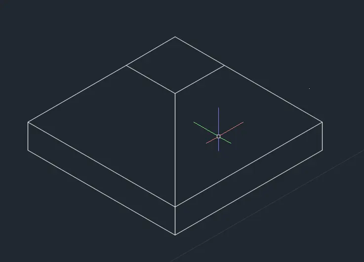
step1:
draw the rectangle for 1'

step2:
draw the line and connect the line to rectangle
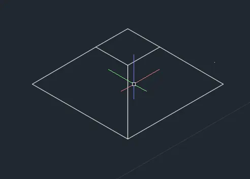
draw the line for depth for 6" and join the lines to the edges
using the dli cmt mention the measurement
RESULT:
3.AIM:
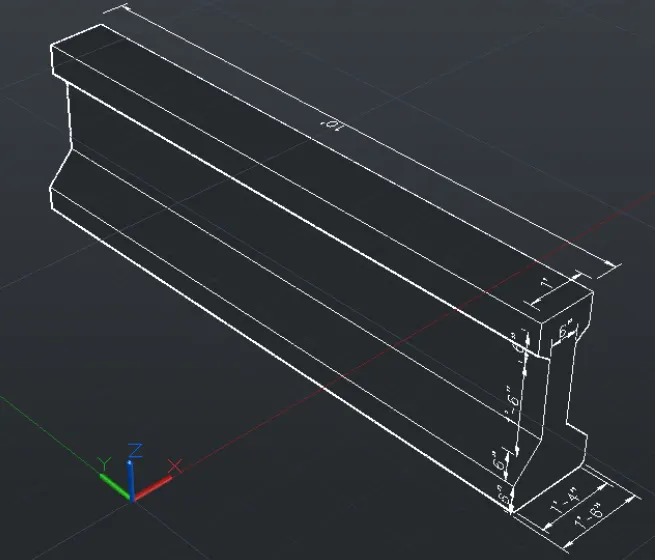
Create the 3D view of the AASTHO Type Girder
PROCEDURE:
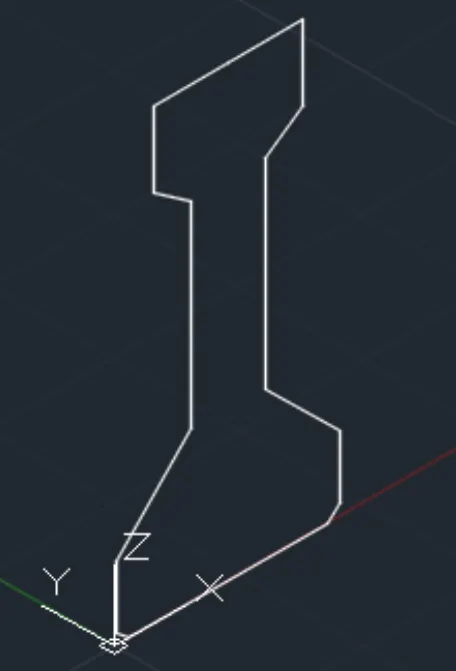
1) now convert the figure to a region that it can be extruded
2) then the figure is extruded at height 10'
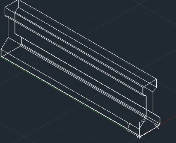
3)now make the visibility to hidden.
4) with the help of ucs coordinates the dimensioning
4) AIM:
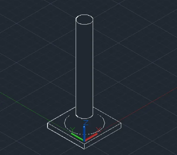
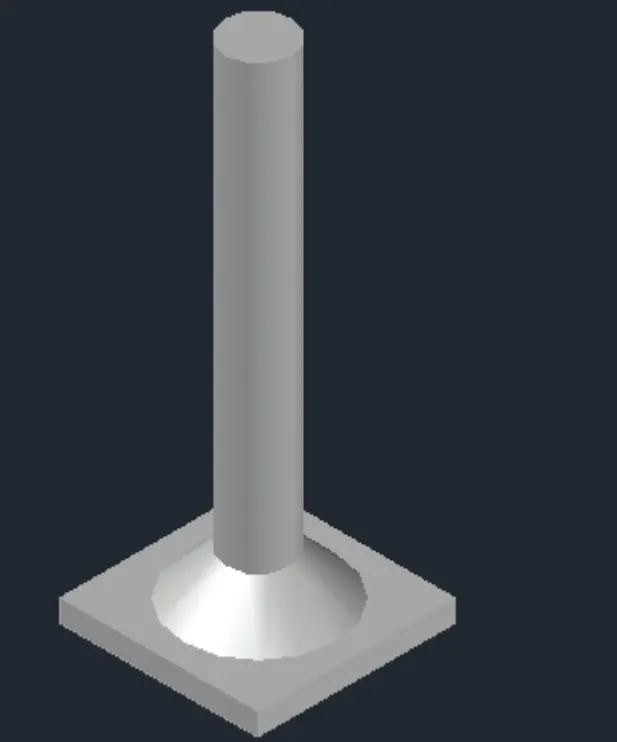
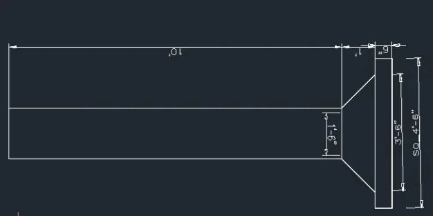
Create a 3d Model of a drop column with panel as shown in section and isometric view.
PROCEDURE:
1. Open the autocad and go to the 3d modeling in the settings and change the work space to 3d modeling
2.now the unit as the architectural feet and inches
3.set the limits
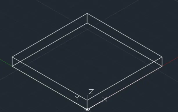
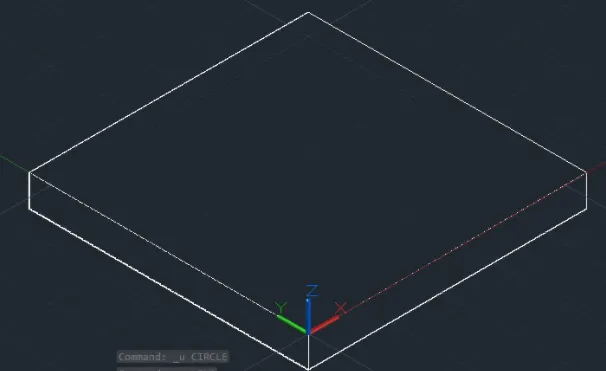
4) A square having the side of 4'6" is constructed in the sw view
5) covert the region and is extruded at the extursion height of 6"
6) then it change to hidden
7) now the centre a circle is created having the diAMETER OF 3'6"
8) For this place the ucs coordinates on the top surface where we need to work
9) convert region and extrude it with tamping(angle 45 degree and height 1')
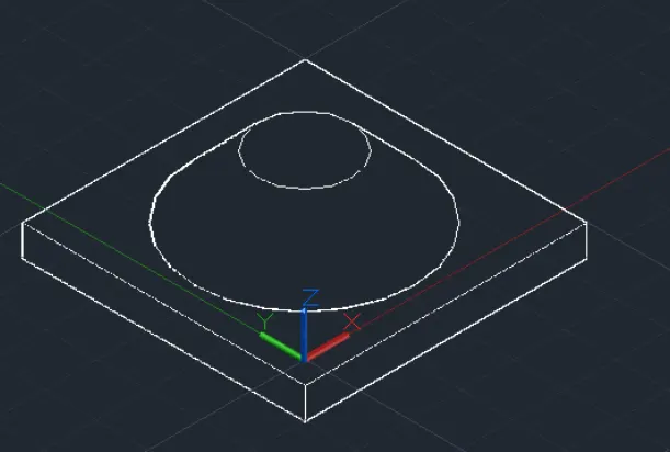
10) explode the tapered and the top of the circle is converted to a region and then extuded at extrusion height
11) change the view to the shaded
12) in the cmt prompt type 3d orbit and change itd view conveniently
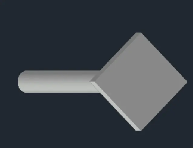
13)change the view to the right and do the dimensioning
RESULT:
5.AIM:
Create the 3d model of a wall as shown in Figure. Consider wall thickness as 9”.
PROCEDURE:
1. Open the autocad and go to the 3d modeling in the settings and change the work space to 3d modeling
2.now the unit as the architectural feet and inches
3.set the limits
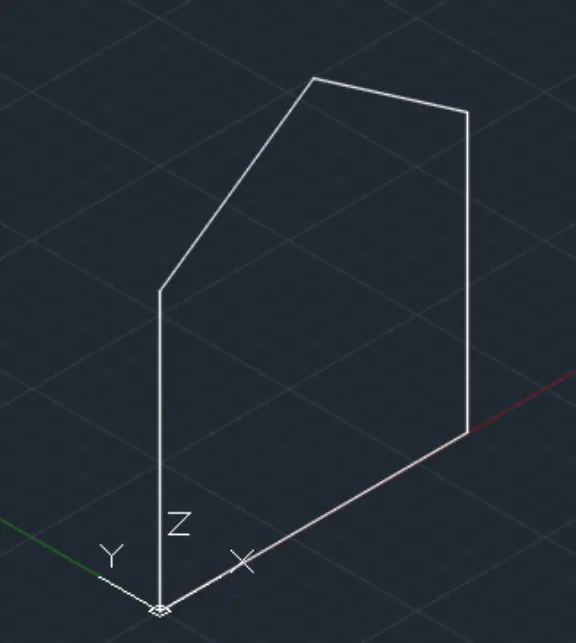
4. Choose the line cmt and make the workspace to sw direction and draw the outline
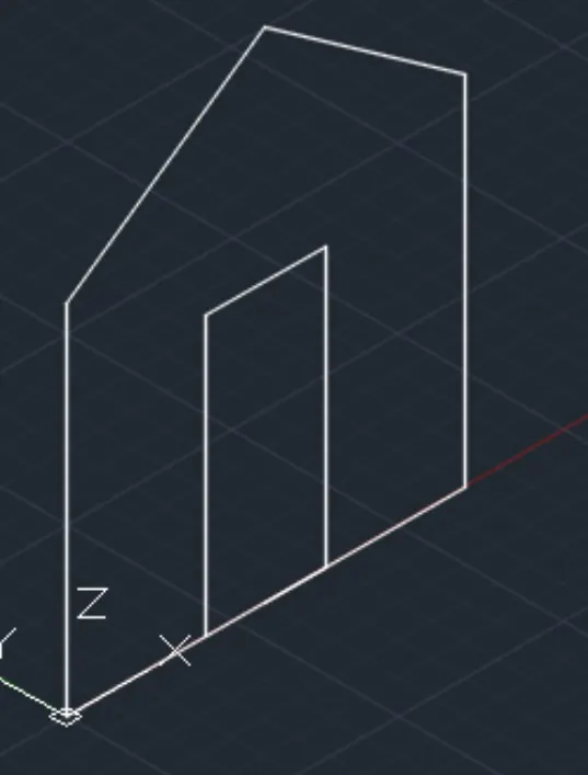
5. using line cmt create the door wall
6. for this initally mark the centre of the bottom line and take 1'6" to both side
7. covert this to region and extrude it backward at the distance of 9" which mark the wall thickness
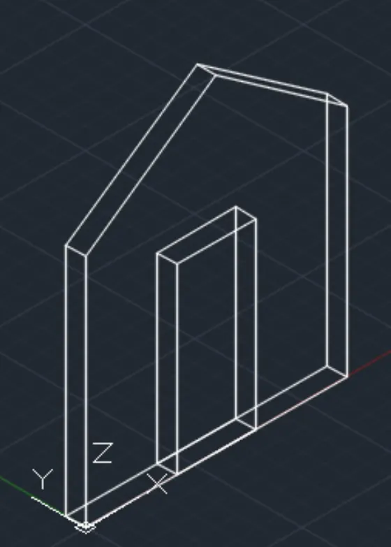
8. now dimensioning is done with the help of ucs orgin option
RESULT: