Creating various 3D Models like Furniture, Footing, Girder, Column drop with panel and Gable Wall in AutoCad
1)
Aim:
Creation of the cube like structure in AutoCAD 3D
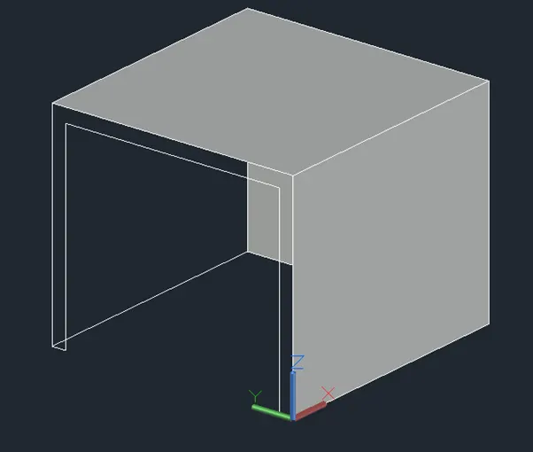
I. In command prompt type (startup:1)
II. Then file>new
III. Then create new drawing window select metric in default settings
IV. In advanced setup in units check on the architectural,angle in degrees, then ok
V. In command prompt type (L) where line command is woken
VI. In command prompt type (specify first point: 0,0,0)
VII. In command prompt type (next point: @3,0,0)
VIII. In command prompt type (next point: @0,0,2’6”)
IX. In command prompt type (next point: @-3,0,0)
X. Snap to the first point by keeping snapping option on.
XI. In command prompt type (next point: @0,2”,0)
XII. In command prompt type (next point: @0,0,2’4”)
XIII. In command prompt type (next point: @0,2’7”,0)
XIV. In command prompt type (next point: @0,0,-2’4”)
XV. In command prompt type (next point: @0,2”,0)
XVI. In command prompt type (next point: @0,0,2’6”)
XVII. Know snap to respective point to create the face
XVIII. In command prompt type (next point: @3,0,0)
XIX. In command prompt type (first point: @3,0,2’6”)
XX. In command prompt type (next point: @0,3,0)
XXI. In command prompt type (next point: @-3,0,0)
XXII. Enter
XXIII. In command prompt type (L) where line command is woken
XXIV. In command prompt type (first point: @0,3,0)
XXV. In command prompt type (next point: @3,0,0)
XXVI. In command prompt type (next point: @0,-3,0)
XXVII. Enter
Result:
The given shape is created in the AutoCAD 3d
2)
Aim:
Creation of the isolated footing in AutoCAD 3d
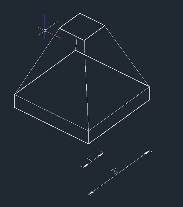
I. In command prompt type (startup:1)
II. Then file>new
III. Then create new drawing window select metric in default settings
IV. In advanced setup in units check on the architectural,angle in degrees, then ok
V. In command prompt type (L) where line command is woken
VI. In command prompt type (specify first point: 0,0,0)
VII. In command prompt type (next point: @3,0,0)
VIII. In command prompt type (next point: @0,3,0)
IX. In command prompt type (next point: @-3,0,0)
X. In command prompt type (next point: @0,-3,0)
XI. Select the all objects and type co in the command prompt and copy all the objects
XII. Specify the basepoint
XIII. And specify the distance as@0,0,6”
XIV. Select the all objects and type o in the command prompt and offset all the rectangle
XV. Specify offset distance as the 1’ and offset inwards
XVI. Select the all objects and type co in the command prompt and copy all the objects
XVII. Specify the basepoint
XVIII. And specify the distance as@0,0,2’
XIX. Now snap the required lines that has to be joined
XX. Enter
Result:
Isolated footing is drawn in the AutoCAD 3D
3)
Aim:
creation of 3D astho type girder
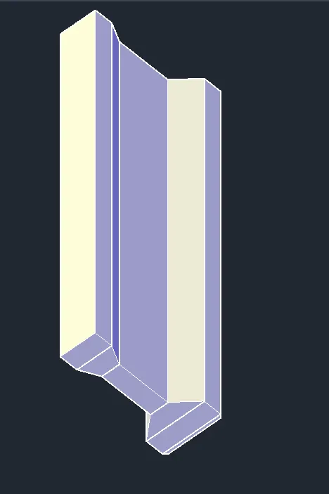
I. In command prompt type (startup:1)
II. Then file>new
III. Then create new drawing window select metric in default settings
IV. In advanced setup in units check on the architectural,angle in degrees, then ok
V. In command prompt type: PLAN and choose the current UCS
VI. In command prompt type (L) where line command is woken
VII. In command prompt type (specify first point: 0,0,0)
VIII. In command prompt type (next point: 1’4”,0,0)
IX. In command prompt type (next point: @1”,1”,0)
X. In command prompt type (next point: @0,5”,0)
XI. In command prompt type (next point: @ -6”,6”,0)
XII. In command prompt type (next point: @0,1’6”,0)
XIII. In command prompt type (next point: @1”,1”,0)
XIV. In command prompt type (next point: @0,6”,0)
XV. In command prompt type (next point: @-6”,0,0)
XVI. In command prompt type (mi) and mirror tool
XVII. And select all the objects and pick end points and draw the perpendicular axis so mirror of the creation is created
XVIII. In command prompt type (3d) and select the 3dface tool
XIX. Create the all the faces required with the 3 point option
XX. In command prompt type (ext)
XXI. Extrude select all the faces
XXII. And specify the distance as 10’
XXIII. Enter
Result:
Required footing is drawn in the AutoCAD
4)
Aim:
Creation of the drop panel column in AutoCAD 3D
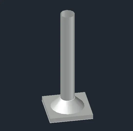
I. In command prompt type (startup:1)
II. Then file>new
III. Then create new drawing window select metric in default settings
IV. In advanced setup in units check on the architectural, angle in degrees, then ok
V. In command prompt type (L) where line command is woken
VI. In command prompt type (specify first point: 0,0,0)
VII. In command prompt type (next point: @4’6”,0,0)
VIII. In command prompt type (next point: @0, 4’6”,0)
IX. In command prompt type (next point: @-4’6”,0,0)
X. In command prompt type (next point: @0, - 4’6”,0)
XI. Select the all objects and type co in the command prompt and copy all the objects
XII. Specify the basepoint
XIII. And specify the distance as@0,0,6”
XIV. Form the rectangle and with the help of the snaping draw the circle of the dia 3’6”
XV. With typing reg in command prompt do region of the rectangle and circle separately
XVI. Again, draw the circle of the dia 1’6” and offset it at the @0,0,1’
XVII. And make this also as the region
XVIII. Now type EXT in the command prompt
XIX. And select the bottom rectangle as the object and specify the extrude distance as the 6”
XX. Enter
XXI. Now type EXT in the command prompt
XXII. And select the big circle as the object and specify the extrude distance as the 1’ and select the tapper angle and type E for the expression and type 45deg as the expression
XXIII. Enter
XXIV. Now type EXT in the command prompt
XXV. And select the smaller circle as the object and specify the extrude distance as the 10’
XXVI. Enter
Result:
drop panel column in AutoCAD 3D was drawn with help of the extrude and other tools
5)
Aim:
Creation of the 3d wall of thickness 9”

I. In command prompt type (startup:1)
II. Then file>new
III. Then create new drawing window select metric in default settings
IV. In advanced setup in units check on the architectural,angle in degrees, then ok
V. In command prompt type (L) where line command is woken
VI. In command prompt type (specify first point: 1’6”,0,7’)
VII. In command prompt type (next point: @0,0,-7’)
VIII. In command prompt type (next point: @3’6”,0,0)
IX. In command prompt type (next point: @0,0,10’)
X. In command prompt type (next point: @-5’,0,2’6”)
XI. In command prompt type (mi) mirror the all the objects along z axis by providing the plane
XII. In command prompt type (reg) create region Select all the objects on the screen
XIII. Enter
XIV. In command prompt type (ext) and select the created region
XV. Along y axis extrude it and specify the distance as the 9”
XVI. Enter
Result:
Required wall the thickness was created.