CREATING SIMULINK MODEL FOR ELECTROMAGNETIC DOORBELL AND A THERMISTOR MODEL TO SENSE THE TEMPERATURE OF A HEATER
AIM:
STIMULATION OF DOORBELL MODEL USING SOLENOID AND THERMISTOR CONTROLLED FAN MODEL
OBJECTIVES:
1) Create a simulink model of ‘doorbell using solenoid’
2) Create simulink model of ‘thermistor to sense the temperature of heater and observe the result by turning on and off the fan by given parameters’
GIVEN DATA:
For given results-
1) For doorbell model, data is assumed.
2) For thermistor,
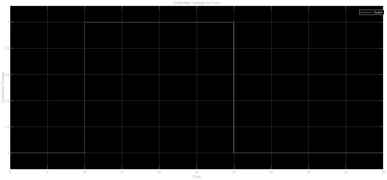
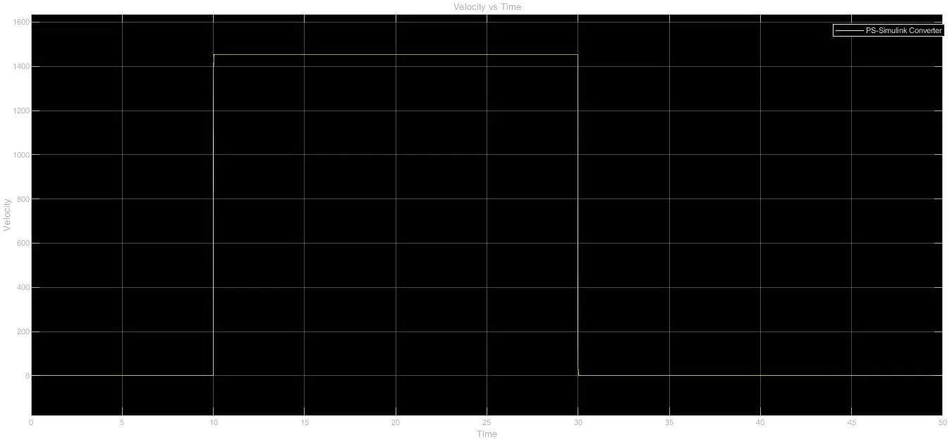
Fan conditions: ON if temperature is above 25 °C, otherwise it stays off
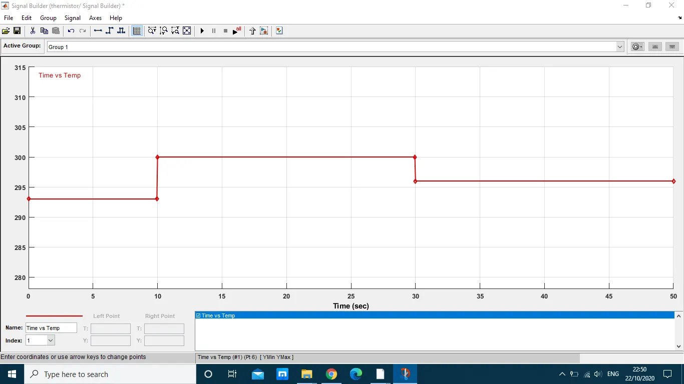
Temperature source variation: 20 °C for 0-10 secs, 27 °C for 10-30secs, 23 °C for 30-50 secs
SIMULINK MODEL-1: DOORBELL USING SOLENOID
Principle: A ringing doorbell uses specialized electromagnet called solenoid. The electromagnet creates electromagnetic field, the wire which is coiled around the electromagnetic conductive metal piston is able to control the forward and backward movement of piston with the help of electromagnetic field.
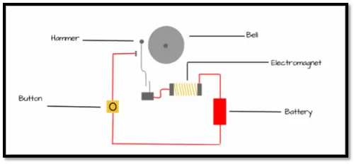
Fig.1. Electromagnetic Doorbell
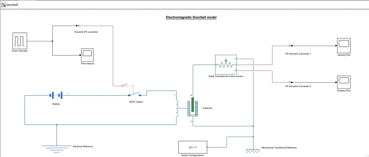
BLOCKS USED IN THE MODEL:
- Pulse Generator - To generatre time signal to cntrol the switch operations
b. Simulink-PS Converter - Converts input simulink signal innto physical signal
c. Scope - For obtaininng the graph for general time, velocity, position domain of the signal
d. Battery - Power Source
e. SPST Switch - ON/OFF control switch
f. Electrical and Mechanical Refrence - Indicating that the connections are grounded
g. Solenoid - For creating electromagnetic field to control forward and backward movement of hammer in the bell
h. PS-Simulink - To converts physical signal to simulink signal
PROCESS EXPLANATION:
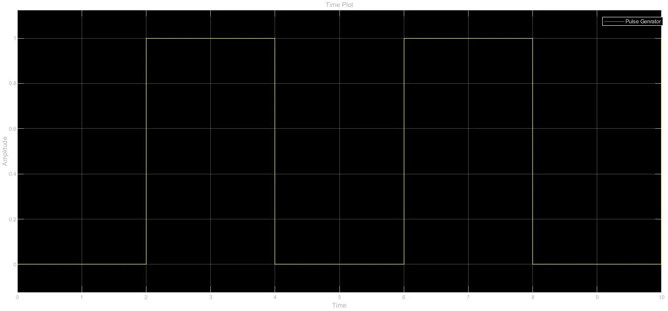
a. Pulse generator gentrates signal for controlling the switch, signal is genrated at every 2 sec.
b. The signals generated by pulse generator are converted to physical signals with the help of Simulink PS converter.
c. Switch controls the flow of current to solenoid hence controlling electromagnetic field.
d. When the switch is in contact, current is passed through solenoid creating electromagnetic field attracting the hammer in the bell.
e. Ideal translational sensor senses the motion of hammer.
f. The signal is again converted to simulink signal for obtaing the motion of the hammer.
OUTPUT:
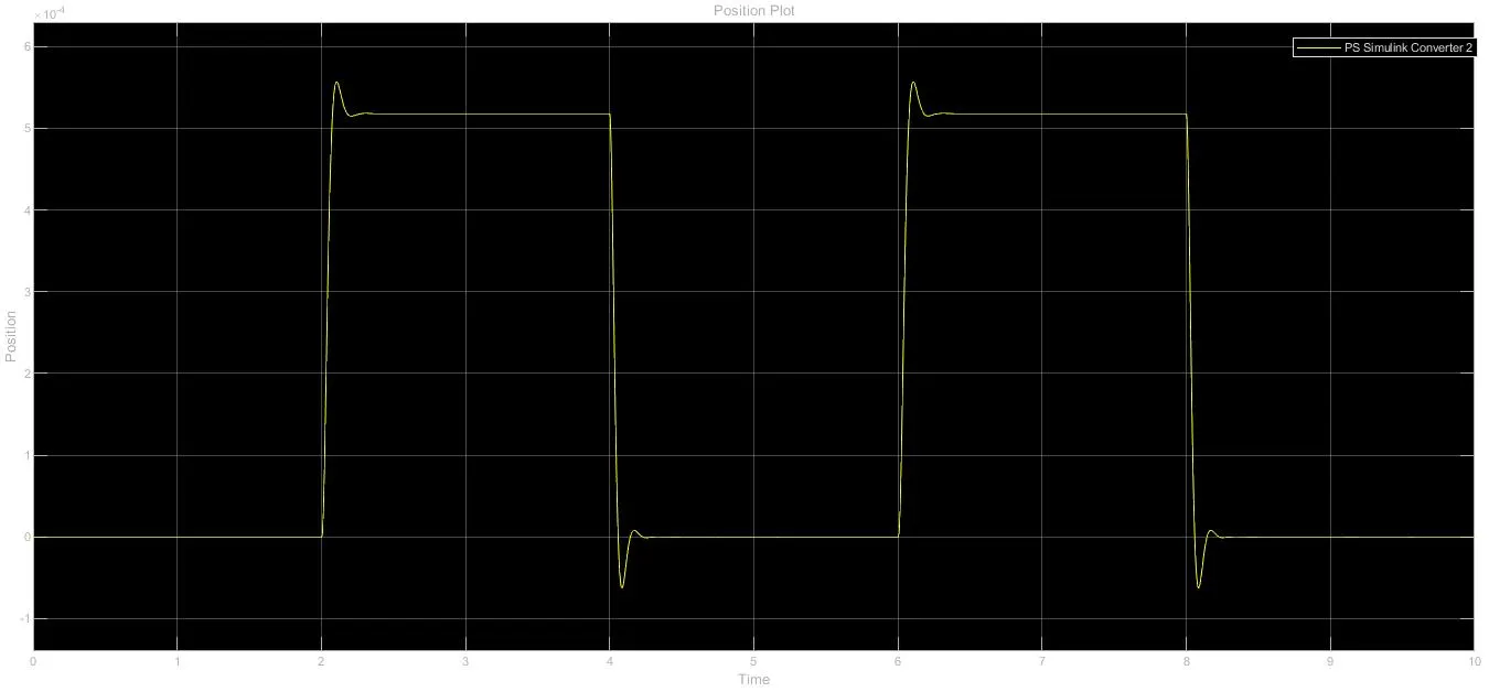
1) TIME PLOT
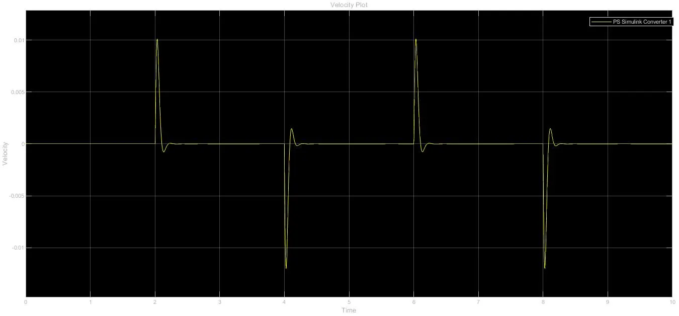
2) VELOCITY PLOT
3) POSITION PLOT
Assumed values in solenoid mechanical parameters,
Spring constant = 100
Damping = 2.5
This reduces the disturbances in the received signal.
CONCLUSION: From the observed outputs, we say see that the pulse is genrated at every 2 secs when the switch on. The velocity and position output confirms that bell ringing for every 2secs.
SIMULINK MODEL-2: THERMISTOR TO SENSE THE TEMPERATURE OF HEATER
Principle: It is a thermal sensitive resistor, the resistance to the flow of current changes with the change in the temperature of the system. When temperature changes the resistance is changesd in a predictable way. The thermistor provides accuracy and stability to the system. They are generally categorised into -
Negative Temperature Coefficient (NTC), resistance decreaases as the temperature rises.
Positive Temperature Coefficient (PTC), resistance increases as the temperature rises.
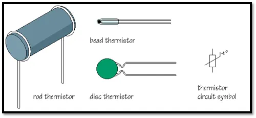
Fig.2. Thermistor
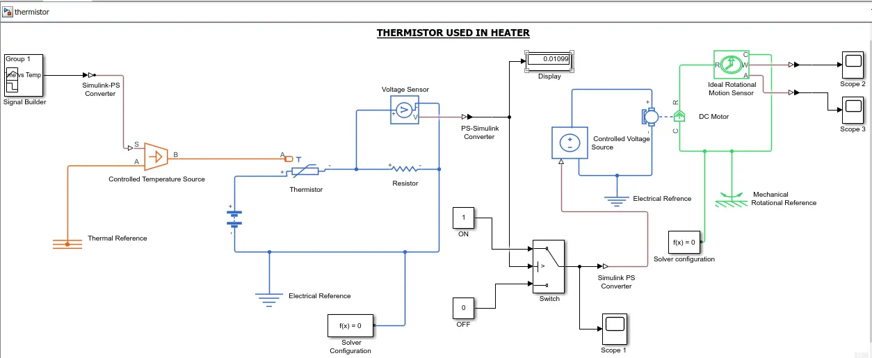
BLOCKS USED IN THE MODEL:
- Signal Builder - Generating the signal by feeding the temperature value at different time interval.
b. Simulink-PS Converter - Converts input simulink signal innto physical signal
c. Thermistor - Senses temperature for adjusting resistance
d. Battery - Power Source of thermistor
e. Electrical and Mechanical Reference - Indicating that the connections are grounded
f. PS-Simulink - To converts physical signal to simulink signal
g. Voltage Sensor - Senses voltage accross the circuit.
h. Display - Shows threshold value of voltage
i. Switch - To control output voltage at particular threshold value
j. Scope - For obtaininng the graph for general time, velocity, position domain of the signal
k. DC Motor - To run controlled voltage
l. Ideal Rotational Motion Sensor - For running the controlled voltage
PROCESS EXPLANATION:
- The signal builder genrates time interval for various temperature as source of heater from the given parameters for heat source, 20 °C for 0-10 secs, 27 °C for 10-30secs, 23 °C for 30-50 secs, Fan conditions: ON if temperature is above 25 °C, otherwise it stays off
b. The temperature data is passed through thermistor where resistance is genrated after evaluating the temperature data
c. Resistance decides the flow of current which varies the voltage
d. The threshold controlled switch is turned ON for which the display shows the threshold value 0.0
e. At 300K, the DC motor is turned on.
f. From Ideal rotional sensor, the output from DC motor is plottted in velocity and angular displacement scope.
OUTPUT:
1) (INPUT/SIGNA BUILDER) TIME vs TEMPERATURE SIGNAL
2) CONTROLLED VOLTAGE vs TIME
3) VELOCITY vs TIME
4) ANGULAR VELOCITY vs TIME
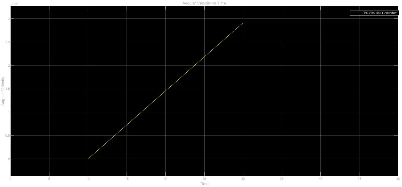
CONCLUSION: From the above plots we can conclude that the fan is controlled by thermistor as it senses the temperature and completes the circuit i.e. turns ON the switch, only when the temperature exceeds T = 25°C, hence it was only turned ON between 10 - 30secs for T = 27 °C.
MODEL FILE:
1) https://drive.google.com/file/d/1Mm7Ha-7VL2rF_-g0hzedr_KAI4c4wszj/view?usp=sharing
2) https://drive.google.com/file/d/15kn0ww5loEHl_wuTv1SL1DOHx5lVzI6R/view?usp=sharing
REFRENCES:
https://www.watelectrical.com/thermistor-working-principle-with-applications/