Creating Levels, Grids, Layout and model elements for a residential unit using REVIT
Ans 1:- Building information modelling (BIM) is an intelligent 3D model -based process that gives architecture, engineering and construction(AEC) professionals the insight and tools to more efficiently plan,design, construct and manage buildings and infrastructure. It isa process supported by various tools, technologies and contracts involving the generation and management of digital representations of physical and functional characteristics of places.Building information models(BIMs) are computer files which can be extracted,exchanged or networked to support decision making regarding a built asset.BIM software is used by individuals, buisnesses and government agencies who plan,design, construct , operate and maintain buildings and diverse physical infrastructure such as water, refuse ,electricity , gas, communication utilities , roads, railways ,bridges, ports and tunnesls.
Features of BIM
- Improved visualization
- Improved productivity due to easy retrievel of information
- Increased coordination of construction documents
- Embedding and linking of vital information such as vendors for specific materials ,location of details and quantities required for estimation and tendering
- Increased speed of delivery
- Reduced costs
- It contains most of the data needed for building performance analysis.
Ans 2:
Cateories in revit means the options that we get after opening the tools , families In revit is actually defined as the similar elements that we add to our revit projects such as walls, roofs, doors , structural members, mechanical equipment or plumbing fixtures, or even annotation elements such as elevation symbols, door tags and column.
Aim:-To understand the concept of families, categories, elements, instances in Revit
Tools / Commands required
Insert tool bar, Load family ,imperial libraries
Procedure
- Open the revit and click on insert
- In the insert load family is visible click on it
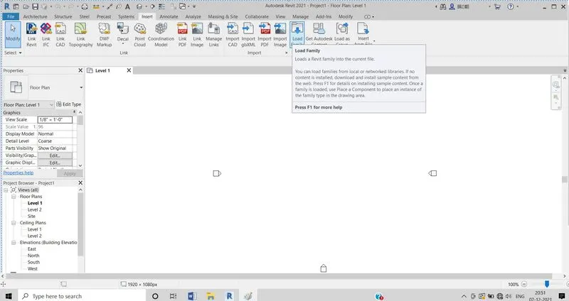
- load family dialog box will appear now select the required family for example click on doors,
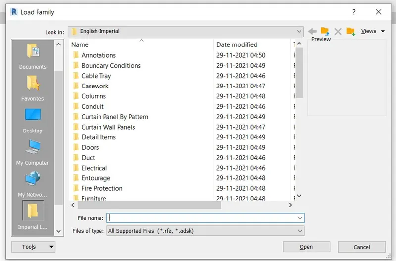
4.in the next we have to select the required door type for example selecting glass doors and click ok.
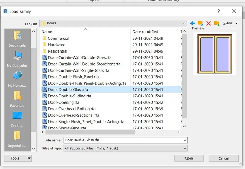
- now we can add our specifications and then click on ok.
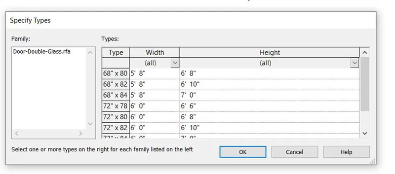
6.now go to Architecture and click on doors the glass door family is being loaded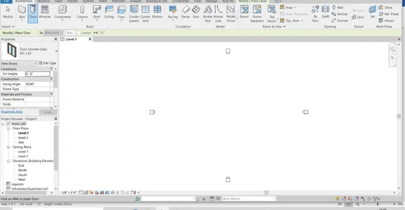
- now just click and drag on the required door family the doors will be appeared.
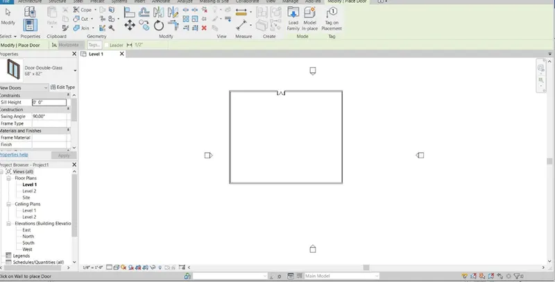
Result:
The required families are being successfuly loaded on the revit model
Ans 3:-
Aim:- setting up a project , opening and saving the file with appropriate name and completing the project information and set up the projects unit as required, under the manage tab with minimum backups for project file to 3.
Tools used:- File,save options,Manage tool bar, Project information, Architectural template , Save option
Procedure:
- Open the revit software
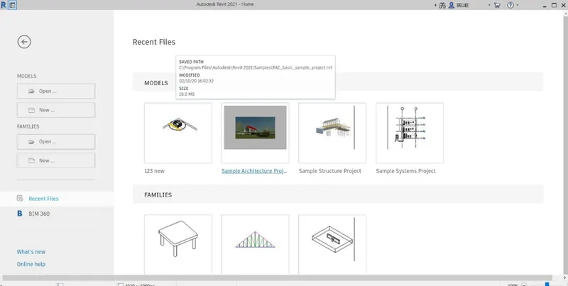
- Select the new and architecture template
- A new project will open.
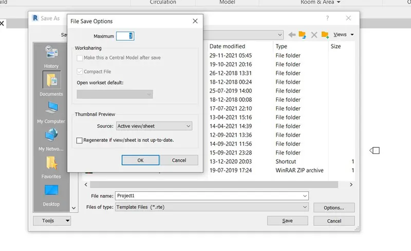
- Now click on File menu and click on the save as .
Save as dialog box will appear there at the right end select option and select the nu,ber of fies you want for back up
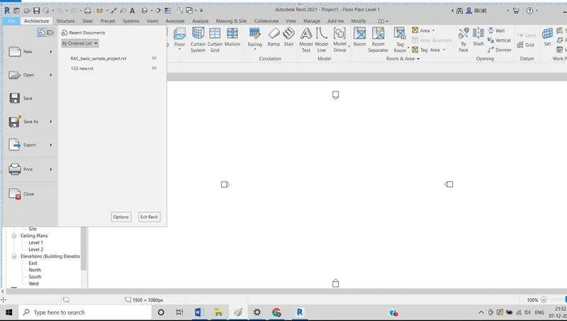
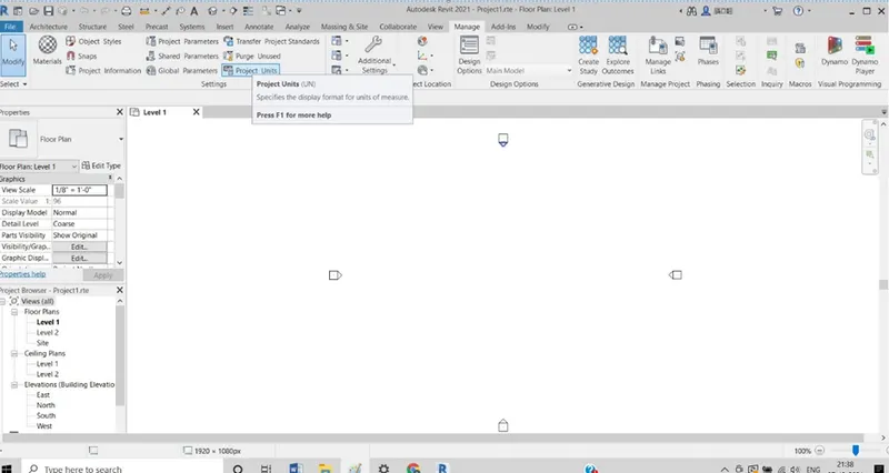
5.in the next step go to manage tool and click on project units
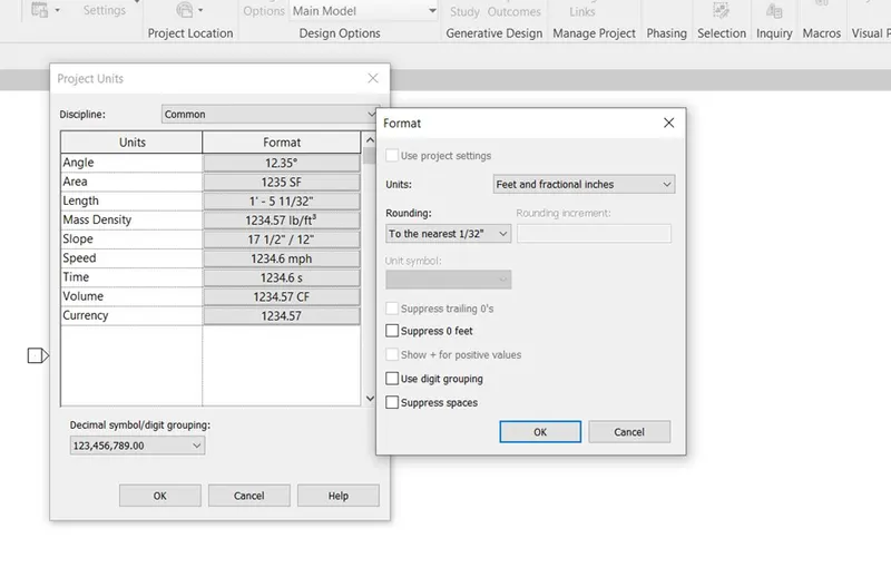
6. project unit dialog box will appear now select the required units by selecting the available options click ok
- now in order to update project information click on file and select project information
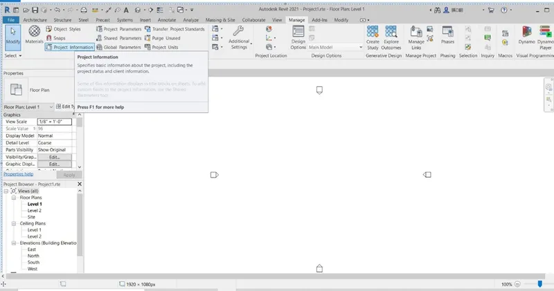
- fill in the all the details required click ok.
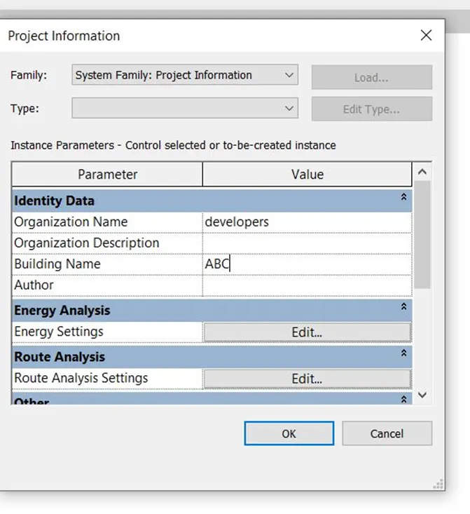
Result:- The given requirements are done in revit model
Ans 4.
Aim:- to understand the concept of grid levels and to create the grid levels
GF @ 0’
FF @ 10’
SF @ 20’
Roof @ 30’
Transverse Grids A,B,C,D,E@ 10’ SPACING
Longitudinal grids from 1 to 10 @ 20’ spacing
Tools used: level,grid
Procedure
- Select any elevation at the left and click ok.
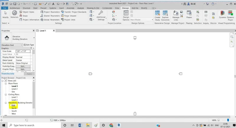
- Now the east elevation will
- Now go to levels and click ok.
- And select on levels to create it
- And add the required levels at required heights.
And select the levels and right click in to it and name the levels as required.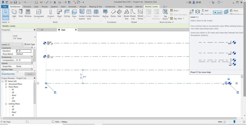
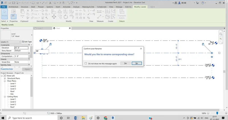
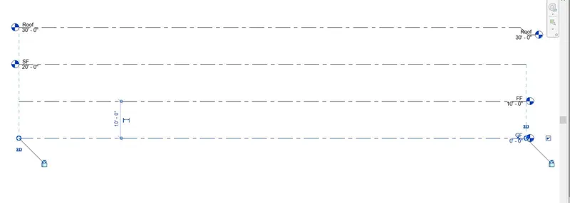
7.
NOW select the gf level and go to Architecture tab then under the datum selct grid and draw the grids as per specified spacings.
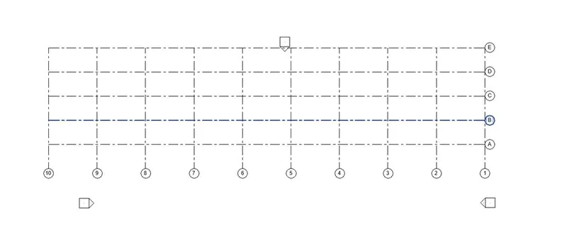
Result:- hence successfully all the levels and grids are drawn.
Ans5:-
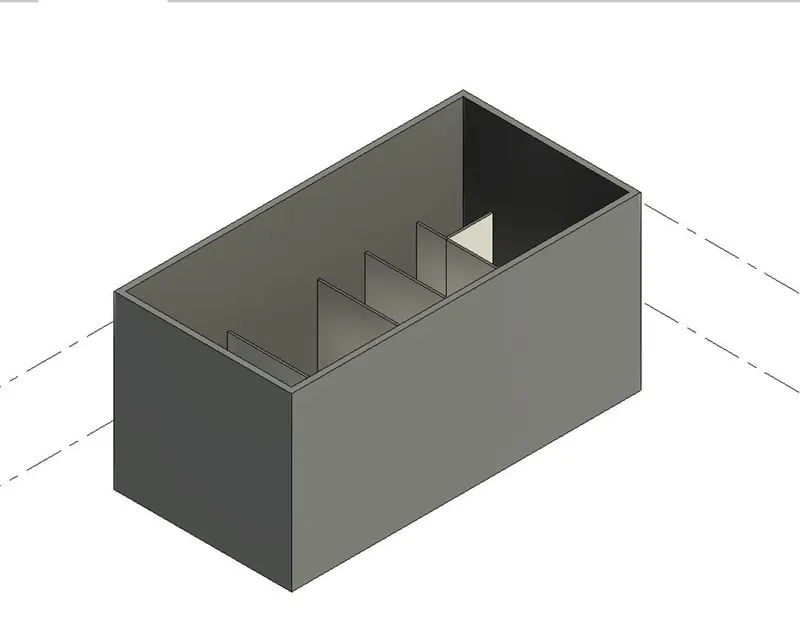
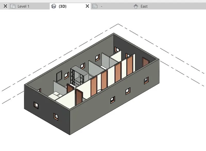
Aim:- To create 3d Modelling of residential unit
Tools used:- Wall Command Archetectural
Procedure:
- First open the revit software and click on new and select architectural unit
- In the next step go to Archetecture tab and click on walls and start draing the walls as per the required dimensions
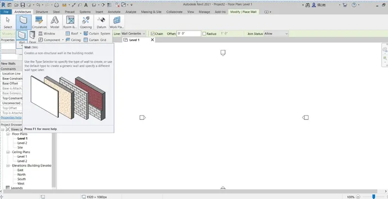
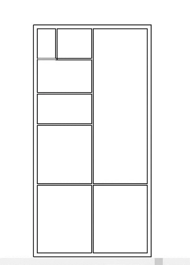
- Next go to view and select #D view to see the 3d View of buildings
-
Result :-successfully created the conceptual residential unit
Ans 6:-
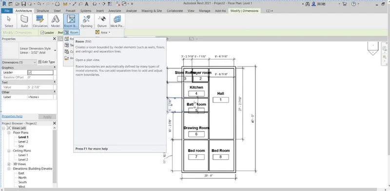
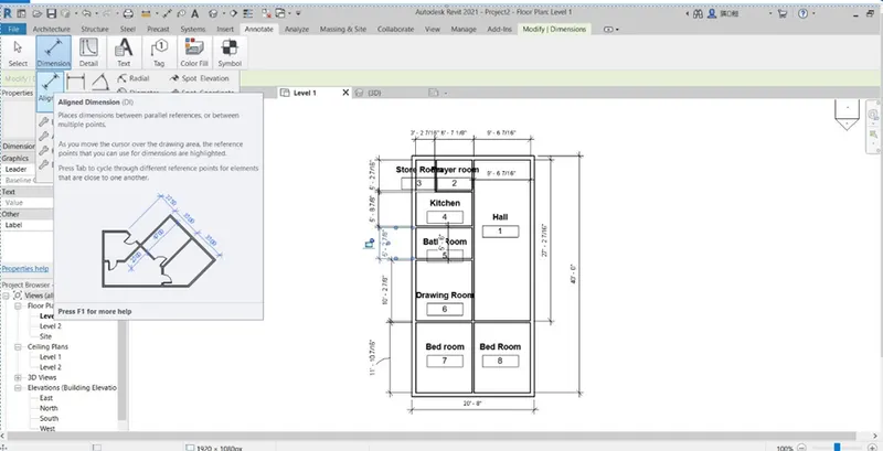
Aim:- To add the dimensions of room, Components in the created lay out
Procedure:
1.Now go to Architecture tab and select Room option.
-
- now select the boundaries and Tags will be added.
- Once the tagging is done rename the rooms as required
Result:
Success fully tagged all the rooms and Dimensioning of the rooms are done using Annotate and Architecture Tools.
Ans7:
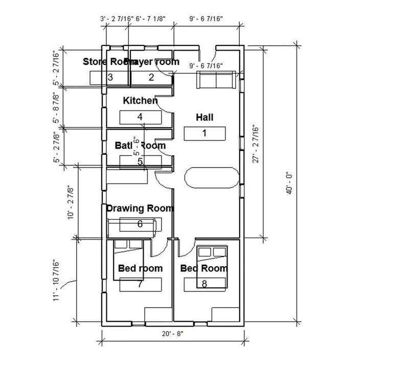
Aim:-To identify the residential model elements such as doors windows table chair couch bed lamps etc
Tools used::- View , Inset, Load family
Procedue
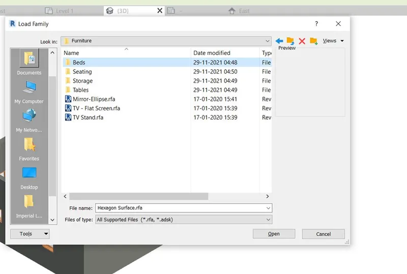
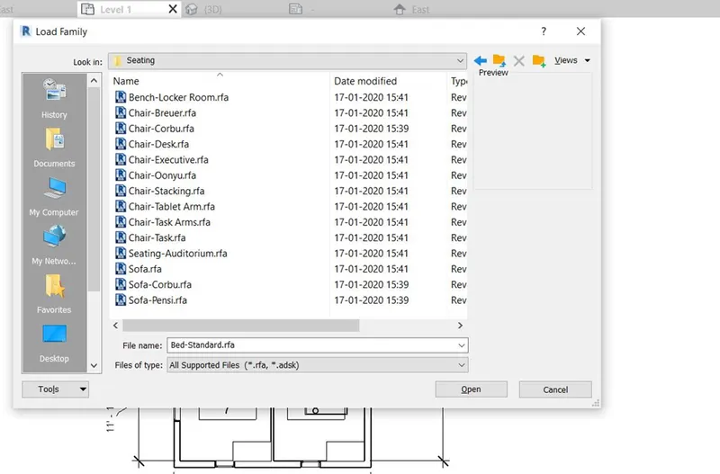
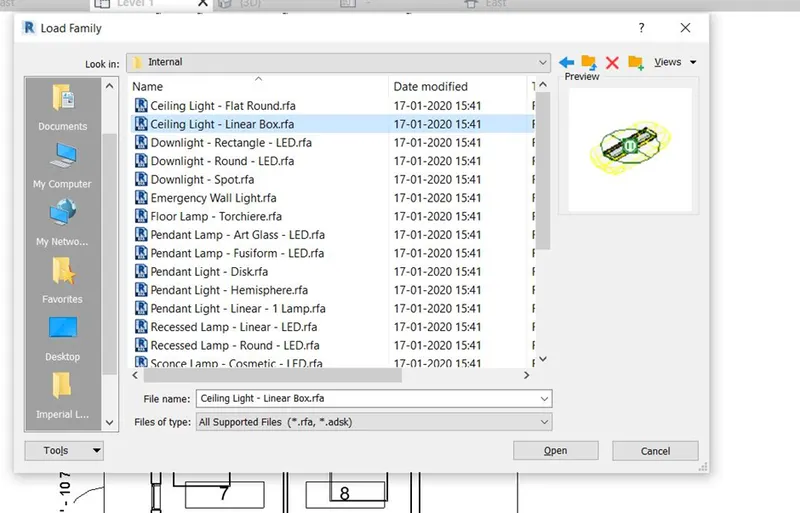
- Go to insert and click on load family
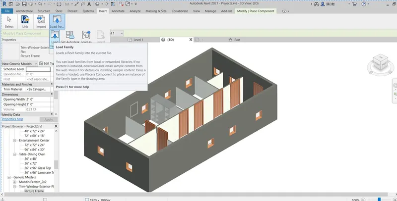
- In the next step select the required element and click ok,
- Go to English imperial and click on furnitures ion orfdre to load the furniture elements
- Go to lighting and click on lamps to load ot
- Similarly click on storages to loads the tables
6.select from the left corner and drag it to plan and ok.
-
Result:-
Successfully all the required elements were loaded in to the plan.