Creating Levels, Grids, Layout and model elements for a residential unit using REVIT
1) What is BIM? Summarize the features of BIM and benefits of using BIM over 2D CAD tools.
BIM stands for Building Information modelling, we can create the models and can create the materials and quantities of the building elements which are of multi disciplines like architectural, structural and MEP. So we can show all the information regarding the project from start to end of the project and also we can give the information for project life time with 3D, 4D, 5D, 6D, 7D, 8D etc.,
Software used for BIM: Autodesk Revit, Archicad, Sketch-up etc.,
FEATURES OF BIM:
- Co-ordination with multi disciplines like architectural, structural and MEP.
- Can create material schedule and quantity.
- We can store the data of the project for its life time.
BENEFITTS OF USING BIM OVER 2D CAD TOOLS:
- With BIM, We can work on multi disciplines in single file.
- If we draw Plan view in BIM tools, it will give the elevation and section views itself.
- And modification is also easy and fast in BIM tools, As if we change in one view, it will be changed in other views also. But in Cad tools we can change separately in all views.
- In BIM tools, if we draw elements, the materials and quantities will come in a single click, but in Cad tools we need to write them.
- In BIM tools, we can see the views like constructed ones.
2) Understand the concept of Categories, Families, Elements, Instances in Revit. Go to Insert Tab, choose a category. Pick a family and element. Understand the instances and insert it to Revit model
Categories: Categories are the type of the families with respect to disciplines elements like wall, door, window, columns, furniture, pipes, stairs, lighting fixtures etc.,
Families: Families are group of elements used in a model.
Elements: Elements are objects with different dimensions in a family.
Instances: Instances are the revit family properties which shown in properties bar of a family.
AIM: Go to Insert Tab, choose a category. Pick a family and element.
PROCEDURE:
Step 1: Open Revit and select a template.
Step 2: At the project mode, click on the Insert toolbar, in that select the “Load family” option

It opens a pop-up
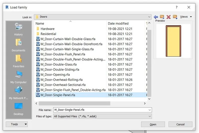
Open the category (Door) and select the family (M_Door-Single-Panel.rfa) in the category folder and click on open. Then revit opens a family selected.
Step 3: At the project mode, click on the Architectural toolbar, in that select the “door” option
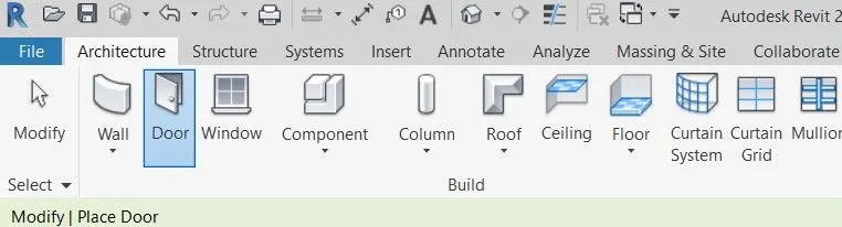
Then we need to drag the family in the model and place it.
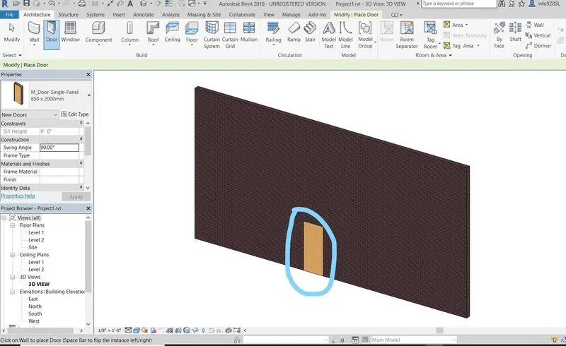
Here we selected the 850 x 2000mm element in M_Door-Single-Panel.rfa family under the category Door.
Result: We have chosen a category and picked the family and element and placed it in the project.
The instances and insert it to Revit model: Instances are nothing but the properties given to revit family, which we can change in model itself, no need to go to the family and change it.
If we change in properties bar, it will change the selected family in model only.
Below images are examples
In door family, I’m changing the height to instance (shown in image) and saving it.
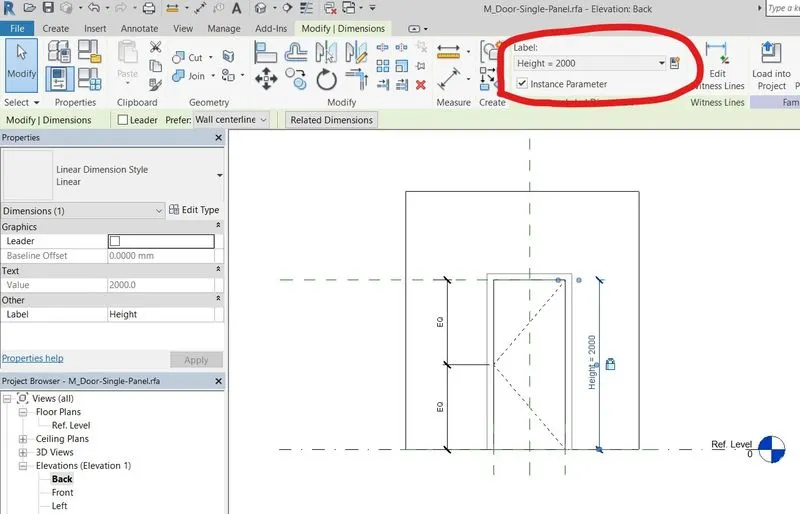
Here length and width are 850 x 2000mm
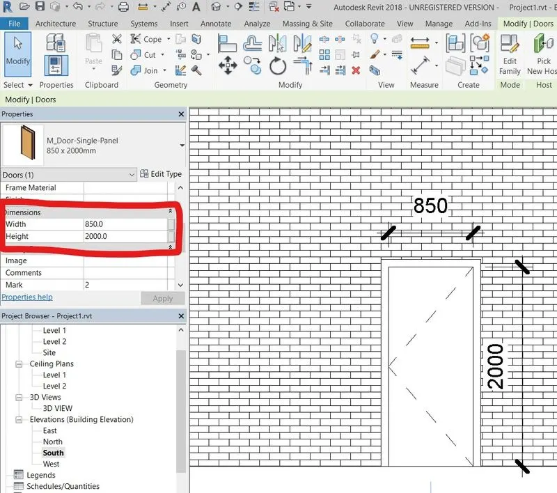
If we change length and width to 1000 x 2200mm
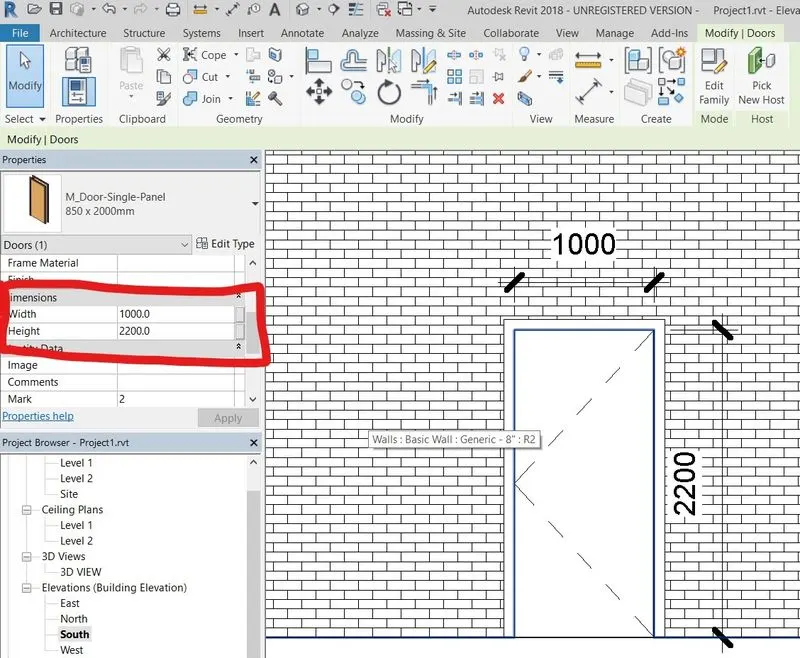
It will automatically change in model itself, without editing family and element.
3) Setting up a Project – Open a project file with architectural template. Save the file with appropriate name. Set up the project units to imperial / Metric based on your convenience of modelling. Complete the project information under Manage tab. Set up the maximum backups for project file to 3
AIM: Setting up a project with below specifications
Open a project file with architectural template. Save the file with appropriate name. Set up the project units. Complete the project information under Manage tab. Set up the maximum backups for project file to 3
PROCEDURE:
Step 1: Open Revit
Click File menu
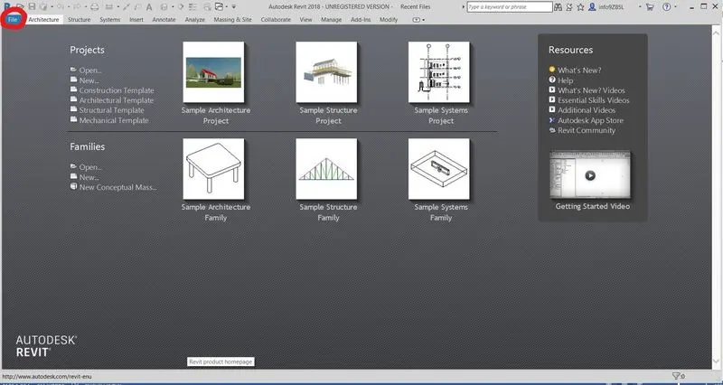
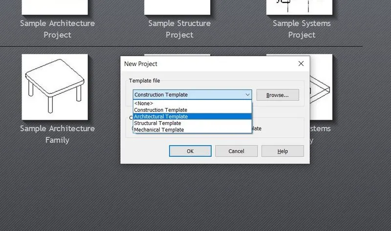
It opens the menu, in that select New, then from new option, we will see a below image
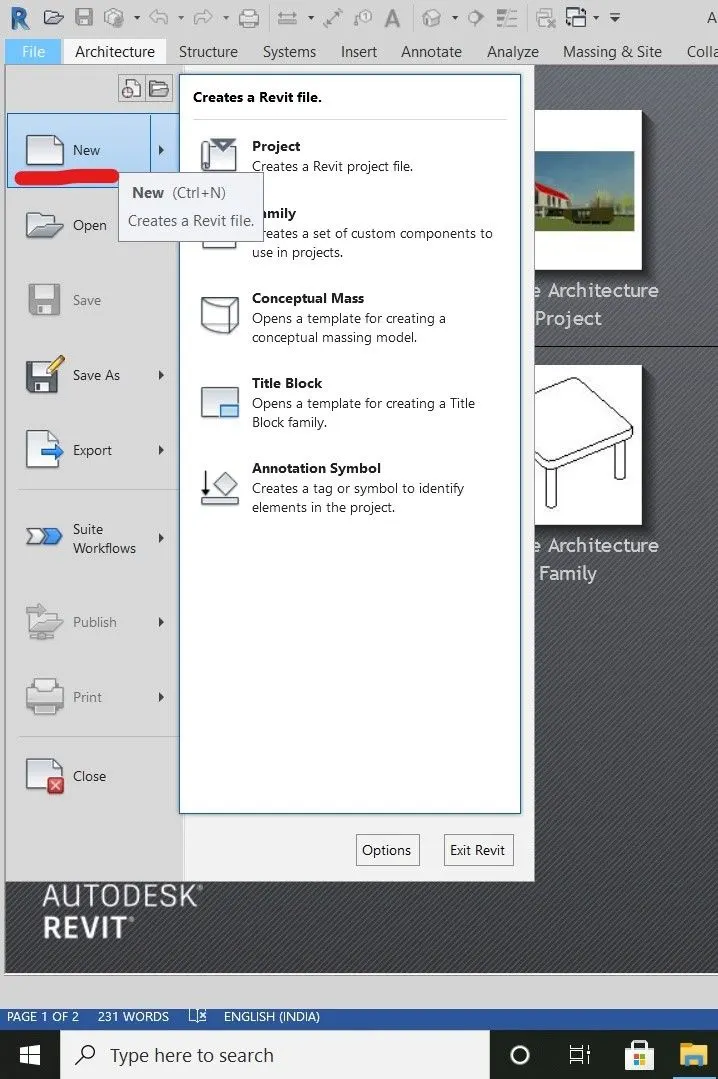
Select Project from the list.
Then it opens a pop-up. Select the architectural and click on OK.
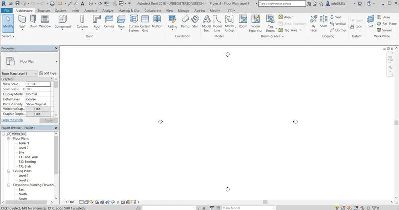
Project mode in Revit
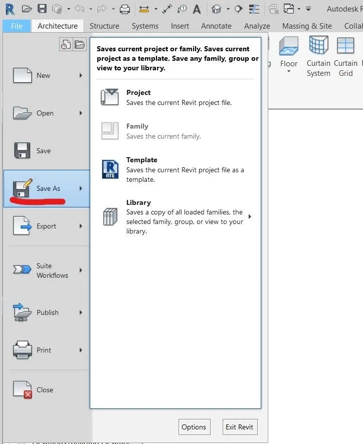
Step 2: Click file and then select save as option and select project
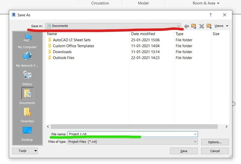
After selecting project it opens a pop-up menu and give the name at the file name as Project 1 and click on save
Step 3: Then open the Manage toolbar and select Project units option

It opens a pop-up
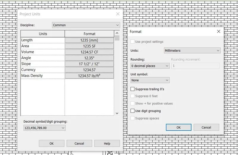
Here we change the Length, Area, Volume, Angle, Slope, Currency and Mass density tabs to toggle from imperial to metric.
Step 4: Under the Manage toolbar, select project information option
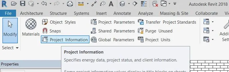
It opens a pop-up
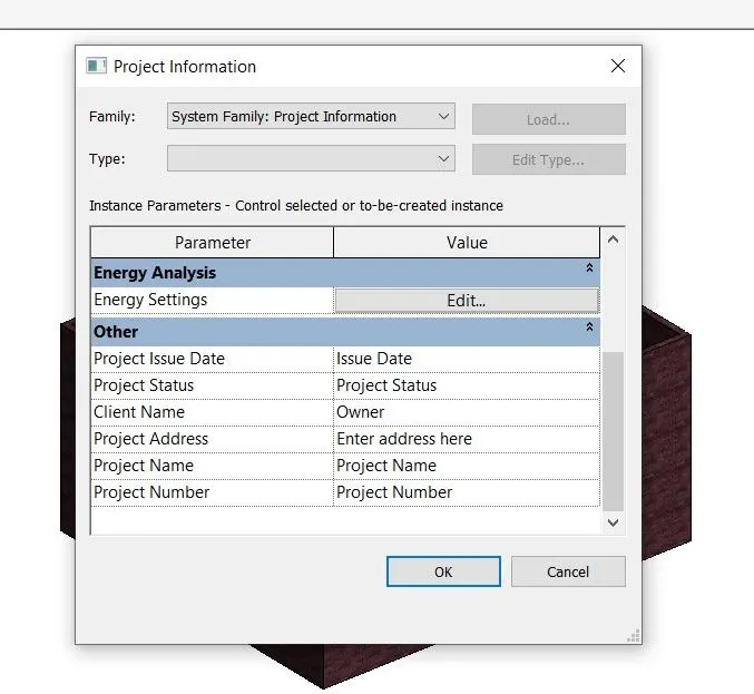
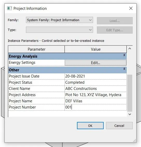
We need to fill the particular details and click on OK, then our project information is stored and it will reflect in the title blocks.
Step 5: For set up the maximum backups for project file to 3,
We need to save as the file, it opens a pop-up
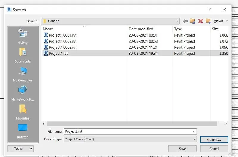
Select options, it also opens a pop-up
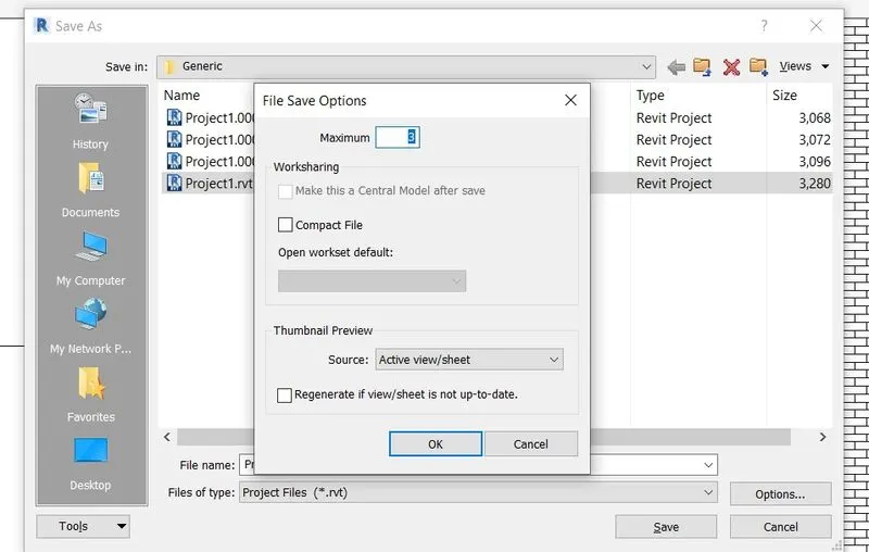
At Maximum tab, we need to type 3, so it will change to maximum backups for project file to 3.
Result: Open a project file with architectural template. Save the file with appropriate name. Set up the project units. Complete the project information under Manage tab. Set up the maximum backups for project file to 3 is done with the above steps.
4) Understand the concept of Levels and Grids. Follow the naming and conventions. Create the following Levels: (Convert to metric equivalents if metric is your units)
Ground Floor @ 0’
First Floor @ 10’
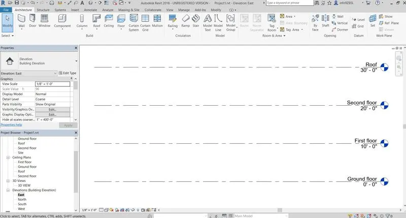
Second Floor @ 20’
Roof @ 30’
Grids Transverse Grids A, B, C, D, E @ 10’ spacing
Longitudinal Grids from 1 to 10 @ 20’ spacing
Levels: Levels are used to represent the floors in the model.
Example: Foundation, Cellar, Ground floor, First floor, Second floor, third floor, roof.
Grids: Grids are used to indicate the drawing elements with construction site in the horizontal and vertical directions with notation of 1, 2, 3, . . . and A, B, C, . . .
AIM: To create the below levels and grids
Ground Floor @ 0’
First Floor @ 10’
Second Floor @ 20’
Roof @ 30’
Grids Transverse Grids A, B, C, D, E @ 10’ spacing
Longitudinal Grids from 1 to 10 @ 20’ spacing
PROCEDURE:
Step 1: Open the architectural template, It opens project mode.
Then click on any elevation in the project browser, I’m opening East elevation.
It opens like below image.
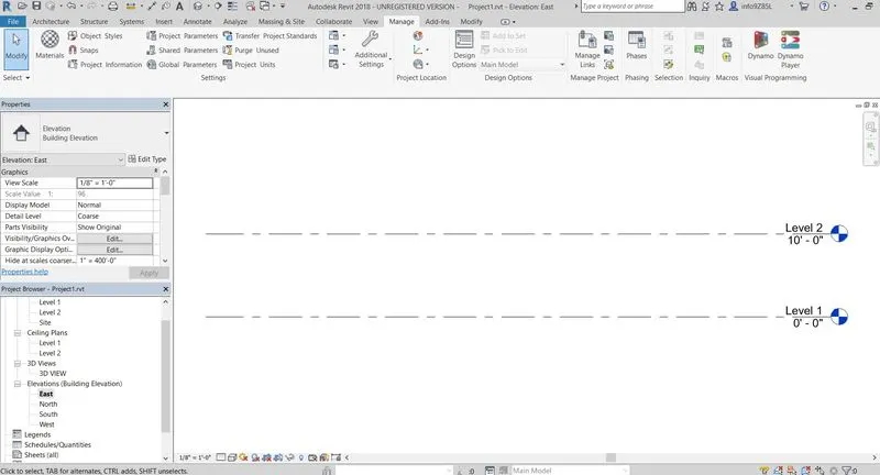
Step 2: Here we need to change the level 1 to Ground floor and level 2 to First floor
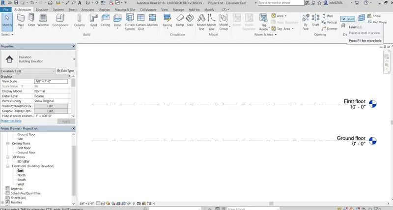
Step 3: Then we need to add the levels from the Architecture toolbar and select Level option.
It will create level 3 and level 4.
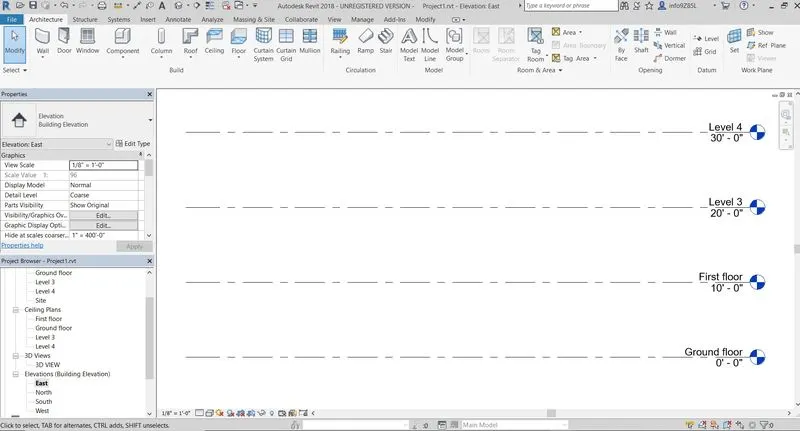
Step 4: We need to change the level 3 and level 4 to Second floor and roof with 20’ and 30’ respectively.
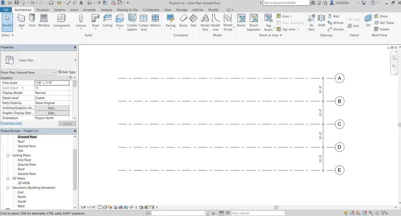
Step 5: For adding grids, we need to open the Ground floor from the project browser.
And add the grids on horizontal side with notations A, B, C, D and E @ 10’ Spacing
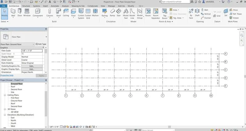
Step 6: Add the grids on vertical side with notations 1 to 10 @ 20’ Spacing
Result:
Created levels and grids like below
Ground Floor @ 0’
First Floor @ 10’
Second Floor @ 20’
Roof @ 30’
Grids Transverse Grids A, B, C, D, E @ 10’ spacing
Longitudinal Grids from 1 to 10 @ 20’ spacing
5) 3D modelling of residential unit – From looking at your house / or a place you aspire. Create a conceptual layout of the residential unit. You can measure using a tape or
you can access your residential plan to create a similar layout.
AIM: 3D modelling of a residential unit
PROCEDURE:
Step 1: Open the architectural template, It opens project mode.
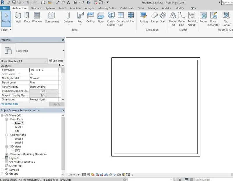
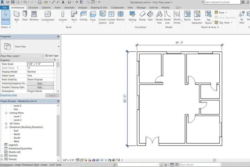
Step 2: Draft the exterior walls of 12” using Wall option in Architecture toolbar.
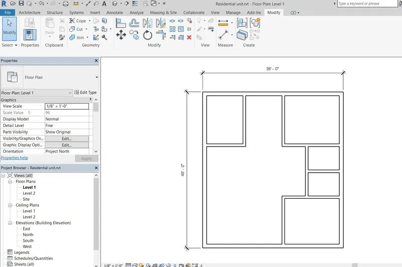
Step 3: Draft the interior walls of 8” using Wall option in Architecture toolbar.
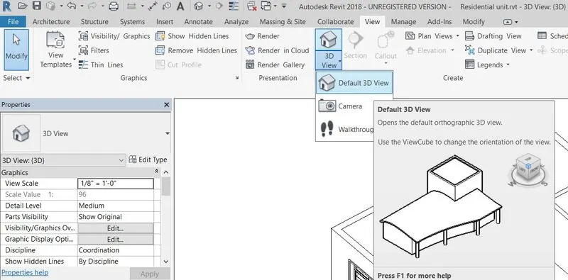
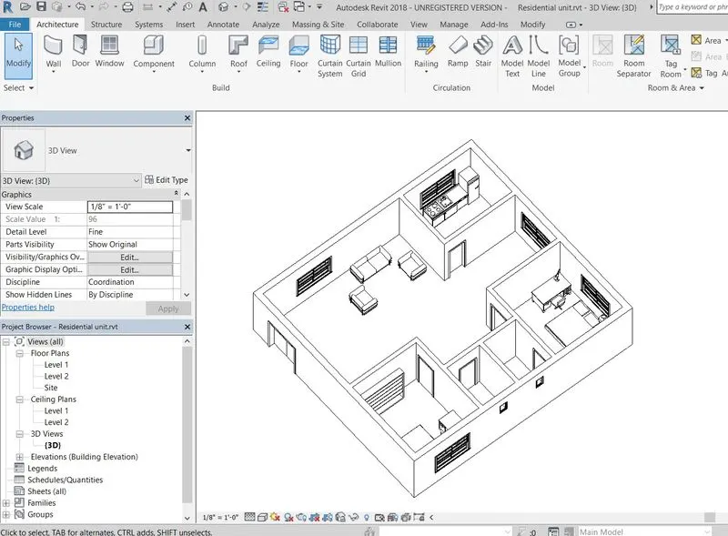
Step 4: From the View toolbar, select 3D View option, in that select Default 3D view.
It opens a 3D view of a residential unit and the new view {3D} added under 3Dviews in the project browser.
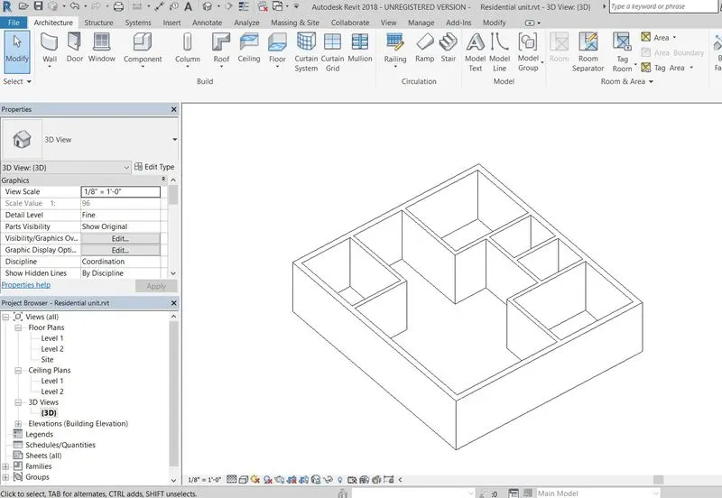
Result: By the above steps we will model the 3D modelling of a residential unit.
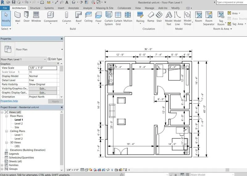
6) In the layout created draft the level of details you are planning to include – Dimensions of room, components you plan to add in the residential unit.
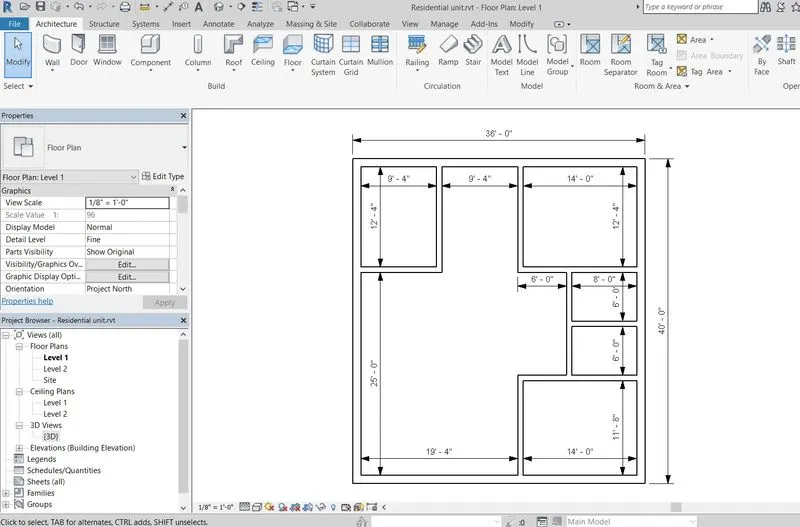
AIM: In the layout created need to add the dimensions and to plan the components which need to add into the rooms in the residential unit.
PROCEDURE:
Step 1: Add the dimensions to the residential unit using Annotate toolbar and select Aligned option
Step 2: Components need to add into the rooms in residential unit like Doors, windows, chairs, tables, sofa, beds, lamps, kitchen items etc.,
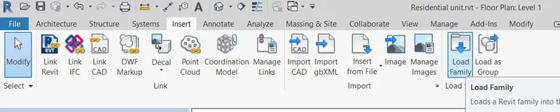
For adding components above, go to insert toolbar and select Load family option.
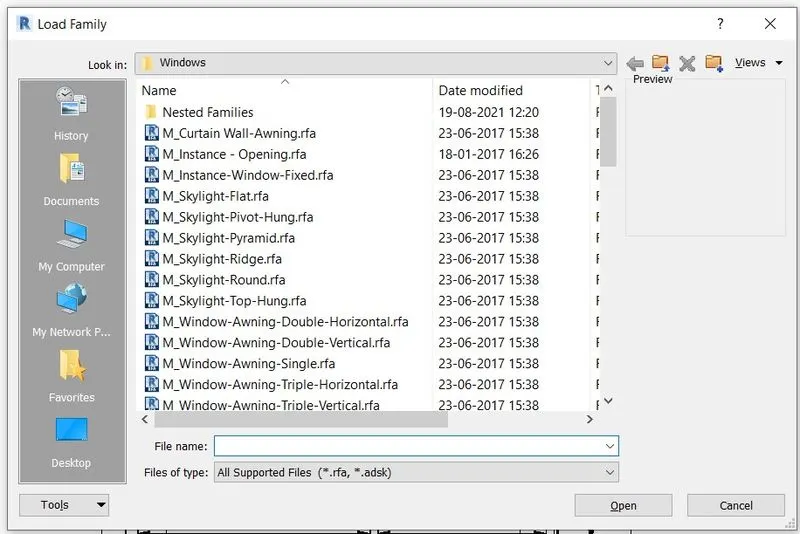
And from the library, we need to select the components from the respective folder and load them into our project (Residential unit)
Result: Added the dimensions to the layout and to added the components which need to add into the rooms in the residential unit.
7) Identify the residential model elements such as Door, Windows, Tables, Chair, Couch, Bed, Lamps from the library and insert them to the model. Save the project for use
for Assignment 3
AIM: To add the residential model elements such as Door, Windows, Tables, Chair, Couch, Bed, Lamps from the library and insert them to the model
PROCEDURE:
Step 1: Add the doors to enter into the rooms using Door option in Architecture toolbar.
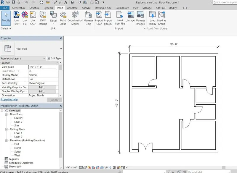
Step 2: Add the windows in the walls using Windows option in Architecture toolbar.
Step 3: Add the tables, chair, couch, bed and lamps in the residential unit with respect to the rooms using Architecture toolbar and select component option and select the components and insert them in model.
3D view of the above plan view
Step 4: Save the project residential unit with ctrl+S or click on file and save.
Result: Add the residential model elements such as Door, Windows, Tables, Chair, Couch, Bed, Lamps from the library and insert them to the model by the above steps.