Creating Levels, Grids, Layout and model elements for a residential unit using REVIT
CREATING LEVELS, GRIDS, LAYOUT AND MODEL ELEMENTS FOR A RESIDENTIAL UNIT USING REVIT
AIM -
- TO STUDY THE CREATION OF LEVELS, GRIDS, LAYOUT, AND MODEL ELEMENTS FOR A RESIDENTIAL UNIT USING REVIT
- THE TARGET OF THESE PROJECTS IS TO SOLVE ALL THE TASKS GIVEN.
INTRODUCTION -
Autodesk Revit is a building information modeling software tool for architects, landscape architects, structural engineers, mechanical, electrical, and plumbing (MEP) engineers, designers and contractors. The original software was developed by Charles River Software, founded in 1997, renamed Revit Technology Corporation in 2000, and acquired by Autodesk in 2002. The software allows users to design a building and structure and its components in 3D, annotate the model with 2D drafting elements, and access building information from the building model's database. Revit is 4D building information modeling capable with tools to plan and track various stages in the building's lifecycle, from concept to construction and later maintenance and/or demolition
Tools and its function -
Navigation - we can use the mouse wheel, Project Browser, or View Cube to open a view and navigate to different areas of the model.
The Project Browser - Located on the lower left of your Revit screen, the Project Browser acts as a table of contents for your project. Use it to navigate and open views of the model. You can organize, sort, filter, and customize the Project Browser to support your workflow.
The Properties - The Properties palette lets you view and modify parameters for selected elements. If no element is selected, it displays the properties of the current view. The palette appears by default to the left of the drawing area above the Project Browser.
Temporary Dimensions - As you create or select geometry, Revit displays temporary dimensions around the element. You can use temporary dimensions to dynamically control the placement of elements. Learn more about Temporary Dimensions
Levels – Levels are finite horizontal planes that act as references for level-hosted elements, such as roofs, floors, and ceilings.
OBJECTIVE -
THE MAIN OBJECTIVE OF THESE PROJECTS IS TO UNDERSTAND HOW TO CREATE A LEVEL AND GRIDS, HOW TO MAKE A LAYOUT, AND HOW TO MODEL ELEMENTS FOR A RESIDENTIAL UNIT USING REVIT
----------------------------------------------------------------------------------------
TASK 1 - What is BIM? Summarize the features of BIM and benefits of using BIM over 2D CAD tools.
PROCEDURE-
Building Information Modeling(BIM):-
- Revit platform for building information modeling is a design and documentation system that support the design drawing and schedule required for the building project. Revit buildings are of three types VIEW ELEMENTS, MODEL ELEMENTS, ANNOTATE ELEMENTS - annotation elements, and datum elements.
- BIM is a holistic process of creating and managing information for building assets based on an intelligent model and enabled by a cloud platform bim integrates structure multi-disciplinary data to produce a digital representation of an asset across its life cycle from planning and design to construction operation.
- Building Information Modelling BIM is a visual representation of the physical and functional characteristics of a facility from inception onwards. As such, it serves as a shared information repository for collaboration throughout a facility's life cycle.
- BIM consists mainly of 3d modeling concepts in addition to information database technology and interpolates software in a desktop computer employment that architects and contractors used to facility and stimulate construction so these techniques allow the members of the project team to generate a virtual model of the structure and all of its systems in a 3d and can be able to share that information with each other
Features of BIM:-
- There are multiple features of bim available in the BIM software's one is the easy access to information - it is the physical representation of both physical and functional characteristics of the building process that provide the very minute detail of the project
- the second one is making the process more expressive- cad software allows the users to work accurately in three dimensions that are length, breath, and depth. However, bim modeling services provide us allow to work in five dimensions that are time and cost apart from length, breadth, and depth. there are able to provide us with accurate cost of materials and estimate precious time schedule projects even as the design is in development
- And finally, the most important feature of these BIM is the comprehensive view of the project BIM model not only presents the 3d geometry view of the structure they provide a more compressive overview of the entire building process. Actually, it covers every component of the process from the geometrical aspect of the design to special relationships from light analysis to the provision of various services from topographical information to the quantity properties, and so on.
Benefits of using BIM over 2D CAD tools:-
- COMPLETE REPRESENTATION- complete representation of the building design it takes more than the building's fourth components of accommodation. for example, BIM allows you to design electrical and HVSC systems as well as the building itself.
- BIM allows you to INSTANT UPDATES in all the components
- TIME CONSTRAINT- BIM model allows you to prefabricate important components ahead of time you won't have to adjust them based on the building design include such components have part of the initial design
- RESOURCE TRACKING- the model that is given to your client update constantly as you work on your project your clients can check at any time which leads to quicker approval of milestones and more efficient project development. Resource tracking is actually a key component of the BIM model you will be able to figure out how much of each resource you need in the design state these improve the flow and efficiency of construction
----------------------------------------------------------------------------------------
TASK 2 - Understand the concept of Categories, Families, Elements, Instances in Revit. Go to Insert Tab, choose a category. Pick a family and element. Understand the instances and insert it to Revit model
CATEGORIES - It is one of the REVIT element hierarchy actually it controls the organisation visibility grafical representation and schedule of the families with in the project.
FAMILIES - Families is the group of 2-D or the 3-D information that server to represent the building or documentation element of the project. Actually it define the parametrical graphical and documentation requiredment also
TYPES - A Type is a specific representation in a Family defined by distinct parametric, graphical, and documentation characteristics which makes it unique from other Types in the Family.
Instance - An Instance is an individual representation of a Type in the Project defined by unique parametric, graphical, and documentation characteristics which makes it unique from other Instances in the Project.
PROCEDURE-
STEP 1
- Go to the Window search box to open a revit workspace.
- In window search bar type REVIT, the icon of revit application will show on the screen
- Click on the icon of REVIT, application of revit will open and the user interface of revit will show on the screen.
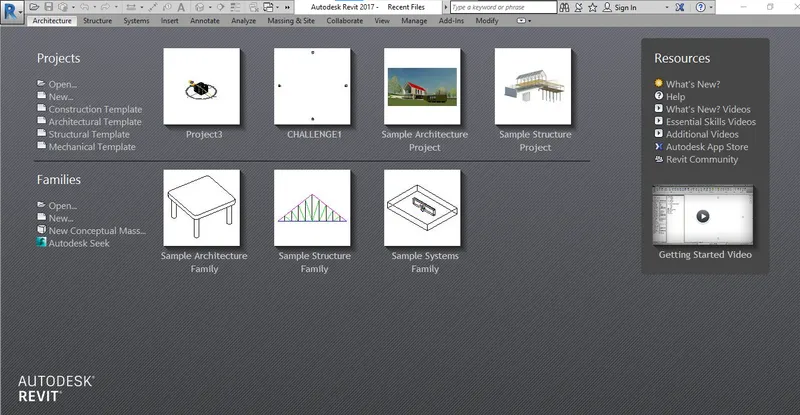
STEP 2
- Click on the Open in the project drop down list to open the exsisting project
- After click on the open the new dialog box will open with all save files.
- Opn any existing file of REVIT
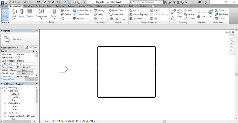
STEP 3
- Go to the Ribbion there is INSERT tab
- Click on the insert tab a insert dropdown will open and there is one tab called as load family
- Click on LOAD FAMILY

STEP 4
- After clicking on load family a new dialog box will open name as Load Family
- In these dialog box we can see the foldr of annotatoon, doors, windows,columns and etc that is nothing but the CATEGORIES.
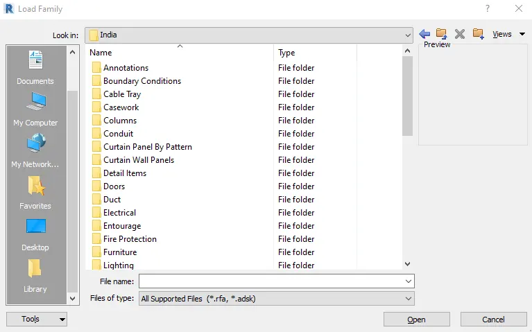
STEP 5
- Click on one of these categories such as door now new dialog box will open and these are nothing but the families
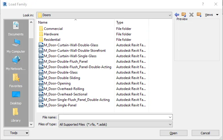
STEP 6
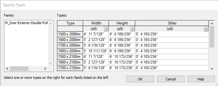
- Now click on one of the type of door such as door exterior double full door
- After clicking a new dialog box will open name as specify type
STEP 7
- Click on any type of door let's take the first one and then press OK.
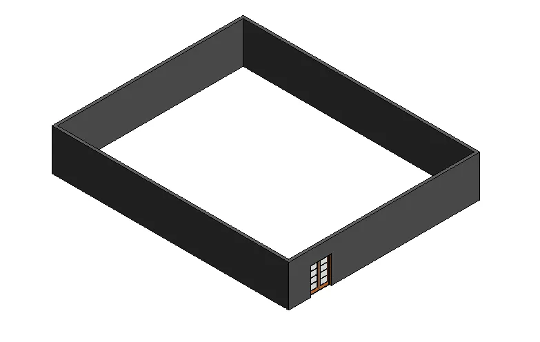
- Specify the location of the door and click on the screen press ESC.
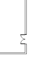
RESULT -
----------------------------------------------------------------------------------------
TASK 3 - Setting up a Project – Open a project file with architectural template. Save the file with appropriate name. Set up the project units to Imperial / Metric based on your convenience of modelling. Complete the project information under Manage tab. Set up the maximum backups for project file to 3
PROCEDURE-
STEP 1
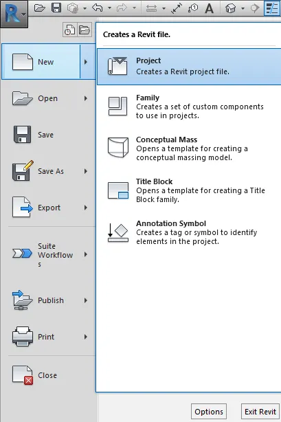
- Click on the application menu or R at the left-top corner of the screen.
- The application menu provides access to common file actions, such as New, Open, and Save. It also allows you to manage files using more advanced tools, such as Export and Publish and close tab to close the revit file.
- Click on thee NEW and then POJECT.
STEP 2
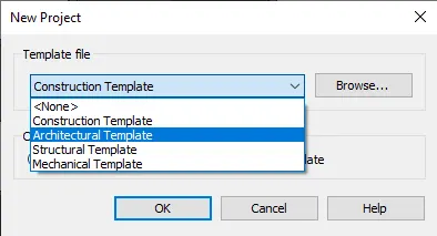
- A new dialog box will open click on drop down and seleect the ARCHITECTURAL TEMPLATE and click on OK.
STEP 3
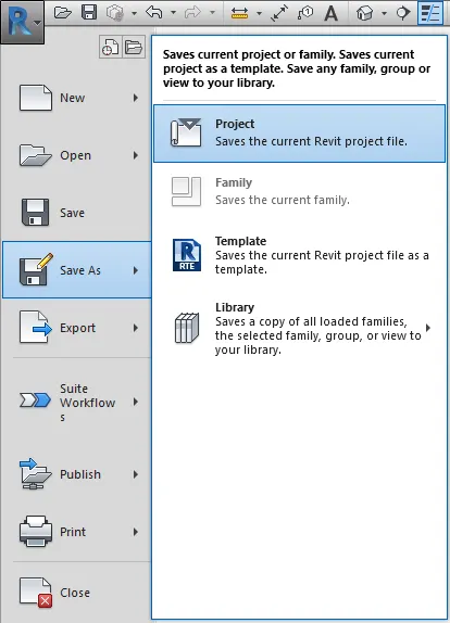
- Click on the application menu or R at the left-top corner of the screen.
- The application menu provides access to common file actions, such as New, Open, and Save. It also allows you to manage files using more advanced tools, such as Export and Publish and close tab to close the revit file.
- Click on save as and select the project tab,
STEP 4
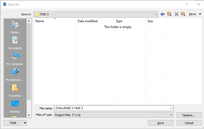
- A dialog box will open name as SAVE AS
- Select a File name and click on save.
STEP 5
- Go to the manage tool bar here is a setting for project work
- Click on the project information
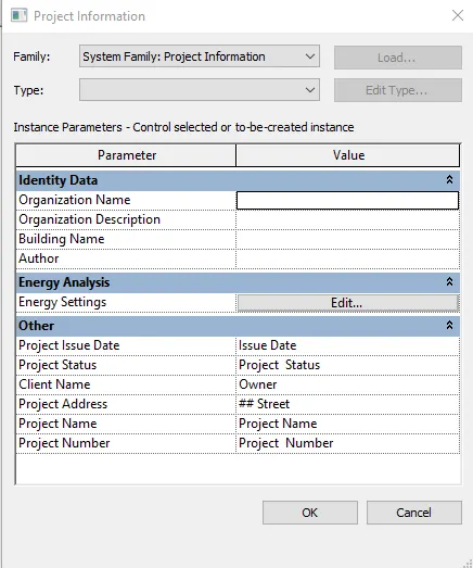
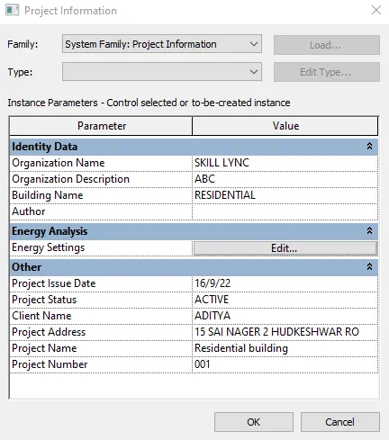
- A new dialog box will open of project information
STEP 6
- In the project information dialog box scrool down we will get the other tab
- Change the Project Issue Date and Project name and other imformation accourding to ous project.
STEP 7
- Click on the application menu or R at the left-top corner of the screen.
- The application menu provides access to common file actions, such as New, Open, and Save. It also allows you to manage files using more advanced tools, such as Export and Publish and close tab to close the revit file.
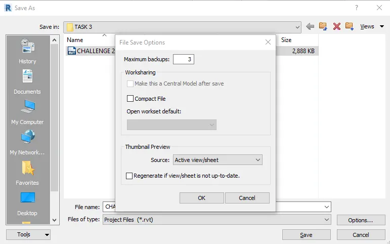
- Click on save as and select the project tab,
- Now click on the option tab and select the maximum backups as 3 as mention in the TASK
----------------------------------------------------------------------------------------
TASK 4 - Understand the concept of Levels and Grids. Follow the naming and conventions. Create the following Levels: ( Convert to metric equivalents if metric is your units)
Ground Floor @ 0’
First Floor @ 10’
Second Floor @ 20’
Roof @ 30’
Grids Transverse Grids A, B,C,D, E @ 10’ spacing
Longitudinal Grids from 1 to 10 @ 20’ spacing
PROCEDURE-
STEP 1
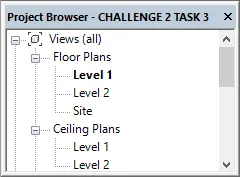
- Too draw the levels we need to go in elevation so.
- Go to the Project Browser and scroll down you will get the elevation tab and click on EAST elevation.
STEP 2
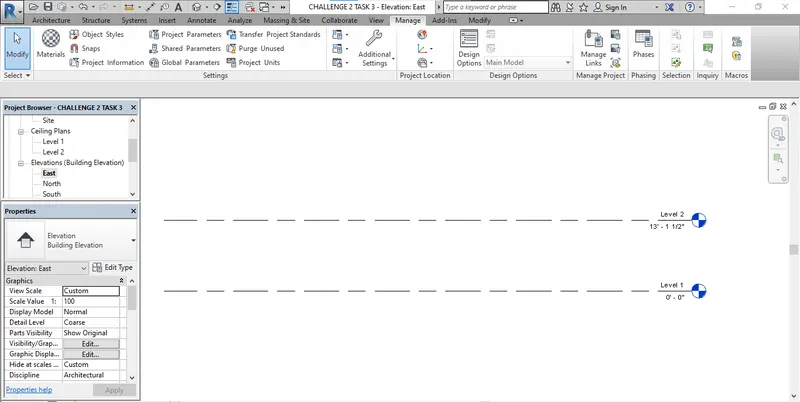
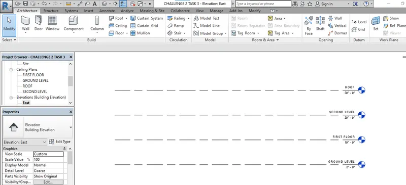
- But, there is already two level created with name level 1 and level 2 and distance between them is 13' - 1 1/2"
- Now go the architecture tab and click on new layer and add two more levels.
STEP 3
- Now click on level 1 and change the name as GROUND LEVEL and distance as 0'0"
- Click on level 2 and change the name as FIRST FLOOR and distance as 10' and again do the same action for SECOND FLOOR and ROOF and distance as 20' and 30' respectively.
STEP 4
- Go to the architecture tab and click on GRID
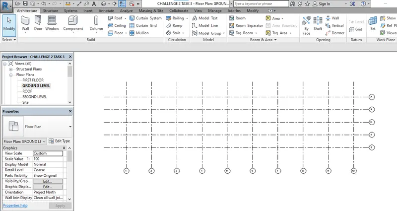
- Select the line from the modify that and create the one horizontal grid name as A and one vertical line name as 1
- Now again select a grid and select the pick line option from the modify tab and specify offset distance as 10' and select horizontal line and create grid from A to E
- again select a grid and select the pick line option from the modify tab and specify offset distance as 20' and select vertical line and create grid from 1 to 10.
----------------------------------------------------------------------------------------
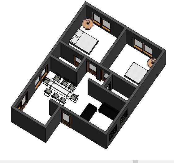
TASK 5 - 3D modelling of residential unit – From looking at your house / or a place you aspire. Create a conceptual layout of the residential unit. You can measure using a tape or
you can access your residential plan to create a similar layout.
PROCEDURE-
STEP 1
- Too draw the levels we need to go in elevation so.
- Go to the Project Browser and scroll down you will get the elevation tab and click on EAST elevation.
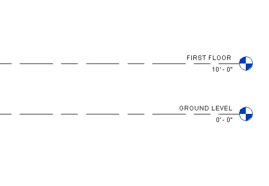
- Now go the architecture tab and click on new layer and add two levels GROUND FLOOR and FIRST FLOOR with distance 10'
STEP 2
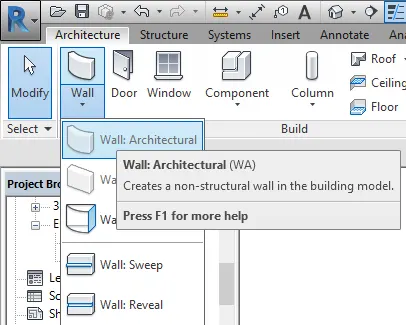
- For these project we required a wall which is present first in the architecture menu bar
- Click on the wall the drop down list of wall will open select the wall architecture that is non structural wall.
STEP 3
- Create a layout accouding to our projeect.
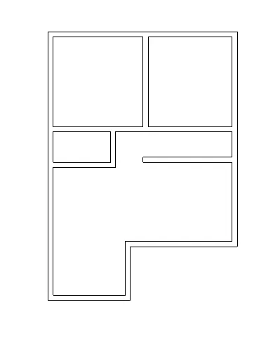
STEP 4
- At the bottom of the left cornor these is menu bar present, in the menu bar there is visual style tab click on that a drop down list will open
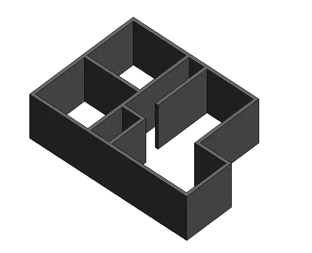
- in drop down list there is 6 type of visual style are present wireframe,Hidden line, shaded, Consistent Colors, Realistic and Ray Treace.
- Click on REALISTIC we will get a realistic view of object
- Now click on 3D
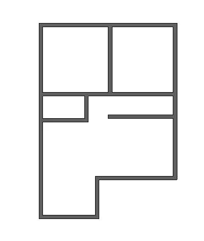
RESULT -
----------------------------------------------------------------------------------------
TASK 6 - In the layout created draft the level of details you are planning to include – Dimensions of room, components you plan to add in the residential unit.
PROCEDURE-
STEP 1
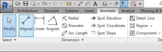
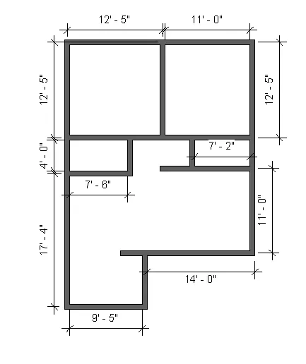
- Go to the ANNOTATE tab in the top menu bar a dimension tool will open.
- Click on the Aligned dimension
- Specify the first point of dimension line as the starting point of wall and the next point is the end point of wall .
STEP 2
- Click on the Linear dimension
- Specify the first point of dimension line as the starting point of wall and the next point is the end point of wall .
STEP 3
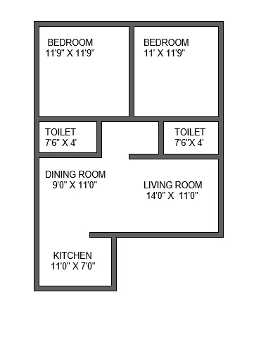
- Go to the ANNOTATE tab in the top menu bar a dimension tool will open.
- Click on the TEXT
- Give the text and dimension to the every room.
----------------------------------------------------------------------------------------
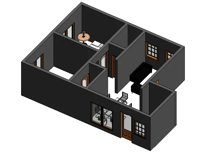
TASK 7 - Identify the residential model elements such as Door, Windows, Tables, Chair, Couch, Bed, Lamps from the library and insert them to the model . Save the project for use
for Assignment 3
PROCEDURE-
STEP 1
- Go to the Ribbion there is INSERT tab
- Click on the insert tab a insert dropdown will open and there is one tab called as load family
- Click on LOAD FAMILY
- After clicking on load family a new dialog box will open name as Load Family
- In these dialog box we can see the foldr of annotatoon, doors, windows,columns and etc that is nothing but the CATEGORIES..
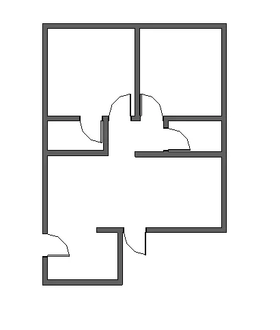
- Click on one of these categories such as door now new dialog box will open and these are nothing but the families
- Now click on one of the type of door such as door exterior double full door
- After clicking a new dialog box will open name as specify type
- Click on any type of door let's take the first one and then press OK.
- Specify the location of the door and click on the screen press ESC.
STEP 2
- Go to the Ribbion there is INSERT tab
- Click on the insert tab a insert dropdown will open and there is one tab called as load family
- Click on LOAD FAMILY
- After clicking on load family a new dialog box will open name as Load Family
- In these dialog box we can see the foldr of annotatoon, doors, windows,columns and etc that is nothing but the CATEGORIES..
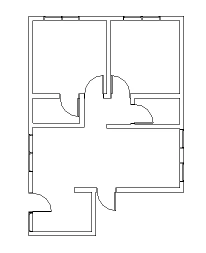
- Click on one of these categories such as WINDOW now new dialog box will open and these are nothing but the families
- Now click on one of the type of WINDOW
- After clicking a new dialog box will open name as specify type
- Click on any type of door let's take the first one and then press OK.
- Specify the location of the window and click on the screen press ESC.
STEP 3
- Go to the Ribbion there is INSERT tab
- Click on the insert tab a insert dropdown will open and there is one tab called as load family
- Click on LOAD FAMILY
- After clicking on load family a new dialog box will open name as Load Family
- In these dialog box we can see the foldr of annotatoon, doors, windows,columns and etc that is nothing but the CATEGORIES..
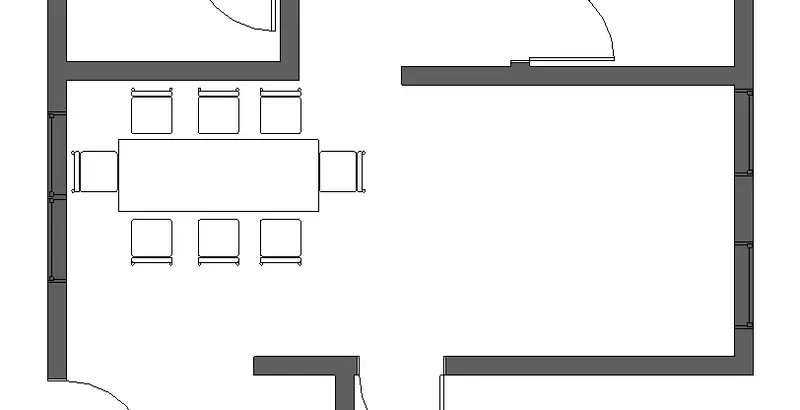
- Click on one of these categories such as furniture now new dialog box will open and these are nothing but the families
- Now click on one of the type of FURNITURE such as TABLE AND CHAIR
- Specify the location of the TABLE and CHAIR and click on the screen press ESC.
STEP 4
- Go to the Ribbion there is INSERT tab
- Click on the insert tab a insert dropdown will open and there is one tab called as load family
- Click on LOAD FAMILY
- After clicking on load family a new dialog box will open name as Load Family
- In these dialog box we can see the foldr of annotatoon, doors, windows,columns and etc that is nothing but the CATEGORIES..
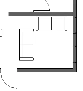
- Click on one of these categories such as furniture now new dialog box will open and these are nothing but the families
- Now click on one of the type of FURNITURE such as COUCH
- Specify the location of the COUCH and click on the screen press ESC.
STEP 5
- Go to the Ribbion there is INSERT tab
- Click on the insert tab a insert dropdown will open and there is one tab called as load family
- Click on LOAD FAMILY
- After clicking on load family a new dialog box will open name as Load Family
- In these dialog box we can see the foldr of annotatoon, doors, windows,columns and etc that is nothing but the CATEGORIES..
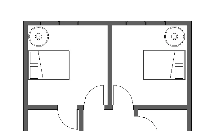
- Click on one of these categories such as furniture now new dialog box will open and these are nothing but the families
- Now click on one of the type of FURNITURE such as BED AND LAMP
- Specify the location of the BED AND LAMP and click on the screen press ESC.
STEP 6
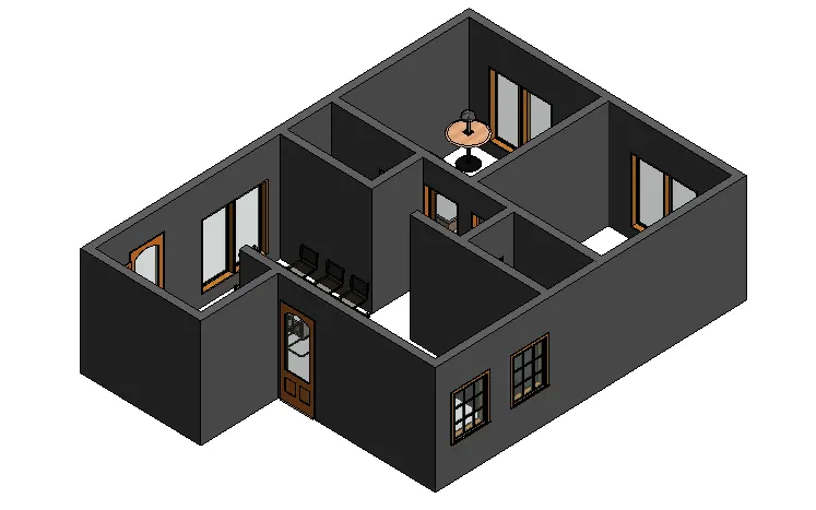
- Click on 3D
RESULT -
----------------------------------------------------------------------------------------