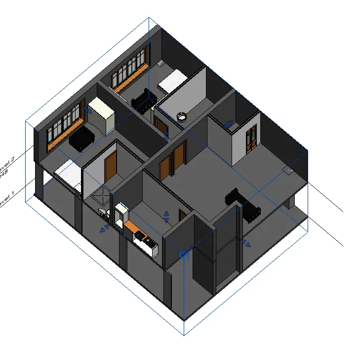
Creating Levels, Grids, Layout and model elements for a residential unit using REVIT
1) What is BIM? Summarize the features of BIM and benefits of using BIM over 2D CAD tools.
Building Information Modeling (BIM) is an intelligent 3D model-based process that gives architecture, engineering, and construction (AEC) professionals the insight and tools to more efficiently plan, design, construct, and manage buildings and infrastructure.
Features of the bim:
• Information can be access easily
• Cost analysis can be done
• Analysis of the models can be done
• high-quality, accurate drawings can be drawn in the software
• more realistic models are obtained
benifits:
• high-quality, accurate drawings can be drawn in the software
• more realistic models are obtained
• single model can contain all the information required for the site information.
• Many users can be working on the single model at a time
• Sharing and collaborating with models is easier than with drawing sets
• BIM offers benefits like simulated views based on different seasonal lighting
• Realistic features like the sun path and other lightings can be modified
• All data required in the project can be managed
• Cost analysis can be done
• Sequence of the work that should go in mentioned
• Lot of detailing drafts can be provided
2) Understand the concept of Categories, Families, Elements, Instances in Revit. Go to Insert Tab, choose a category. Pick a family and element. Understand the instances and insert it to Revit model
Categories:
They are the different types of the family which are divided as per there usage in the projects and it controls the organization, visibility, graphical representations, and scheduling options
Families:
Families can be divided into 3 types as the system, loadable and in-place families
where system families are the commonly used families as the door, window and roof systems and
the loadable families are those which we can use in building the building, system, annotation systems.
Whereas the in-place families are those unique elements that can be created by us which are not present in Revit or the creating the desired families
Elements:
Elements in the Revit are the products of the items that are present in the particular families which we intend to add to the project.
Instance:
These are the particular elements of the families that are added to the project
3) Setting up a Project – Open a project file with architectural template. Save the file with appropriate name. Set up the project units to Imperial / Metric based on your convenience of modelling. Complete the project information under Manage tab. Set up the maximum backups for project file to 3
Aim:
setting up the project
procedure:
• Open Revit from the window and then in the Revit tab
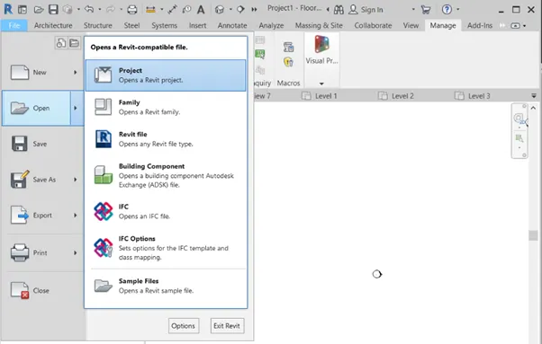
• click on the file option
• here select the project option
• next browse for the file that u intend to open and click on it
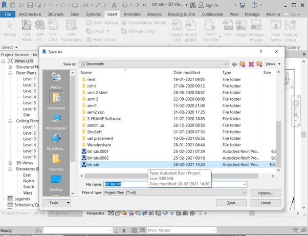
• rename the file to required name and save the file by clicking on the save button
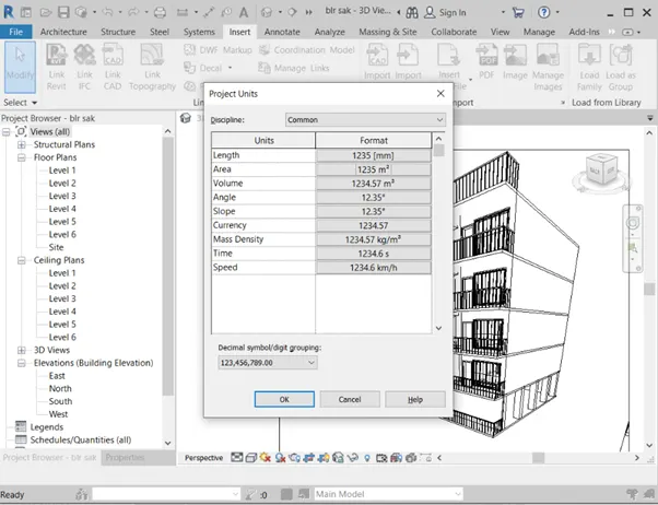
• in keyboard type the UN then units’ settings will be popped up
• where we can change the units to the required units
• now click on the options button and set the maximum of the backups of the file as 3
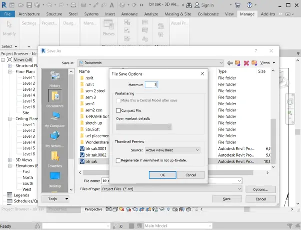
• next go to the manage toolbar and the click on the project information option where in the pop up fill all the required information of the project.
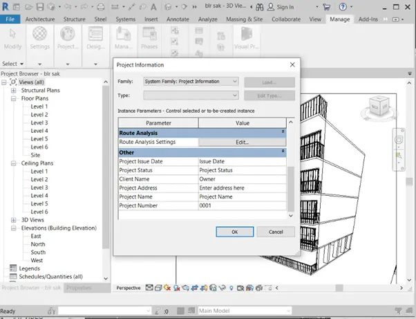
4) Understand the concept of Levels and Grids. Follow the naming and conventions. Create the following Levels: ( Convert to metric equivalents if metric is your units)
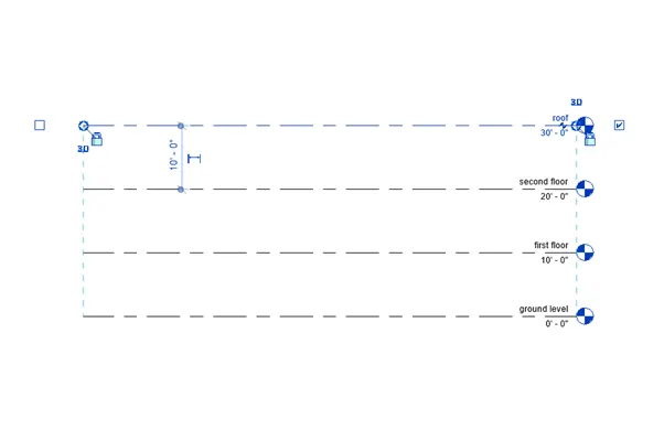
Ground Floor @ 0’
First Floor @ 10’
Second Floor @ 20’
Roof @ 30’
Aim:
creation of the grids and levels
• Open the Revit file
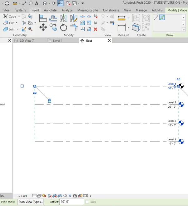
• In the project browser click on the any required elevation
• Go to the architecture tool bar and select the level option
• Here select the pick lines option
• Then provide the offset of 10’ in the offset command bar
• Then with the help of the ground level as the reference offset the level in the vertical direction
• Next click on the annotation and then rename it as required.
Grids Transverse Grids A, B, C, D, E @ 10’ spacing
Longitudinal Grids from 1 to 10 @ 20’ spacing
• In the project browser click on the floor plan view
• Then click on the architecture tab and select the grid option
• Now select the line command and draw the traverse and the longitudinal lines
• In the traverse line attribute type, A
• Similarly in longitudinal line attribute type, 1
• Now select the pick line command
• And specify the offset as the 10’
• And click on the transvers grids for 5 times
• Next specify the offset as the 20’
• And offset the longitudinal grids for the 10 times
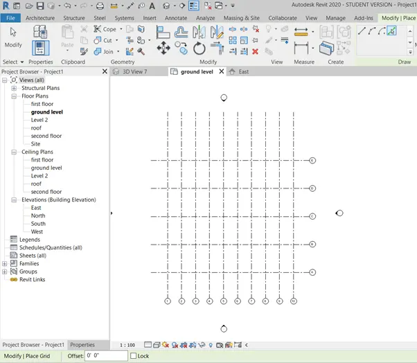
Result:
requried grids and the levels were drawn in the revit.
5) 3D modelling of residential unit – From looking at your house / or a place you aspire. Create a conceptual layout of the residential unit. You can measure using a tape or
you can access your residential plan to create a similar layout.
aim:
creation of the layout
procedure:
• In menu bar click on architecture menu and then select the wall
• Draw horizontal wall of 8919mm
• Then continue the wall to 12192mm
• Again in negative x-direction type 8919mm
• And by snapping close the wall boundary
• Next draw the wall at 5127 from bottom horizontally and after 1500 vertically draw another wall of 2047 and connect it to bottom wall at 1716mm
• At bottom wall from the mid point connect the wall to the horizontal wall
• From the connecting wall draw the other wall of 1981and connect the boundary
• Similarly repeat it in the left side
• 3000mm from the right draw other wall connecting other horizontal wall
• Select all the walls and in the properties browser mention the top constraint as the 1st floor
• Therefore the 3d model is created
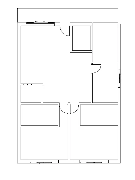
Result:
layout was created in the revit
6) In the layout created draft the level of details you are planning to include – Dimensions of room, components you plan to add in the residential unit.
aim:
providing annotations for the layout
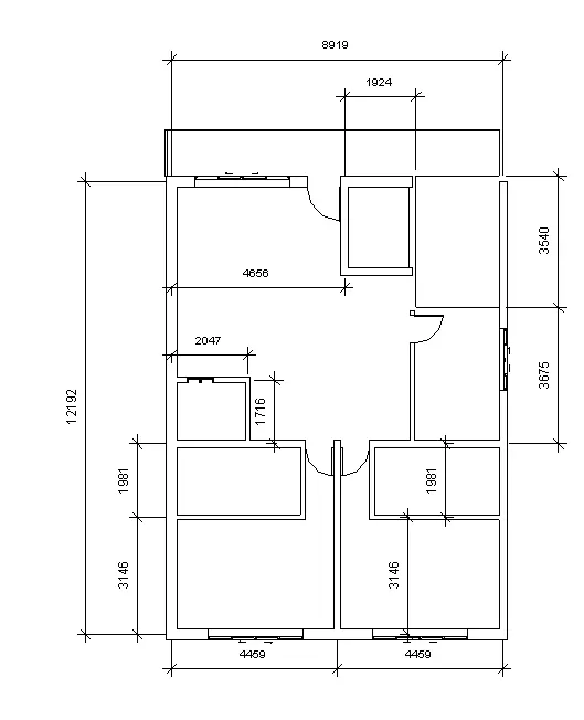
• In the menu bar go to the annotate bar and select the aligned dimensions option
• Now select the walls in which distance between has to be measured
• First click on the first wall
• And then click on the next wall
• Similarly measure the all the required dimensions
• Next got o the architecture tool bar and select the door option
• Clicking on the door in the properties bar select the type of the door
• Now with the help of the snapping place the door
• Move the cursor on the wall where the door has to be placed and snap on the wall
• Next go to the architecture tool bar and select the window option
• Clicking on the window in the properties bar select the type of the window
• Now with the help of the snapping place the window
• Move the cursor on the wall where the window has to be placed and snap on the window
result:
annotations were provided to the created layout
7) Identify the residential model elements such as Door, Windows, Tables, Chair, Couch, Bed, Lamps from the library and insert them to the model . Save the project for use for Assignment 3
Aim:
placing the components in the layout
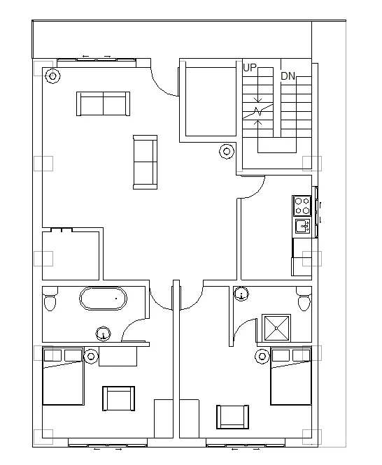
• Go to menu bar and select the architecture bar and
• Click on the component option
• Next click on the load family
• In the popup tab in the following categories
• Select the required families
• And select the elements like the tub, chair, sofa, table, chair
• Select all of them and load them to the project
• Now in the architecture tab select the component
• In properties tab click on component
• Drag down will be appeared and then select the required size of the loaded elements
result:
all requred components were loaded and added to the project