Creating Kitchen layout, Hatching of Architectural elements and sectional view of an Industrial Building in AutoCad
AIM :
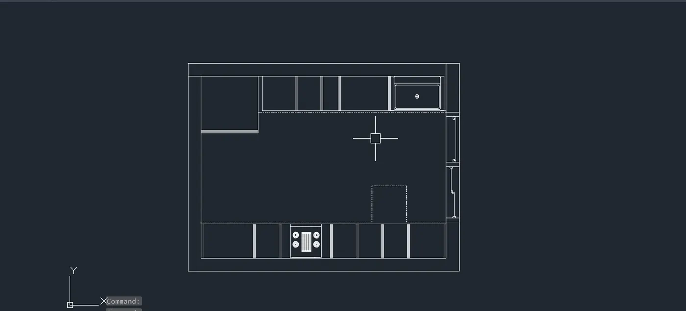
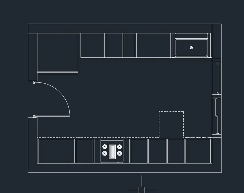
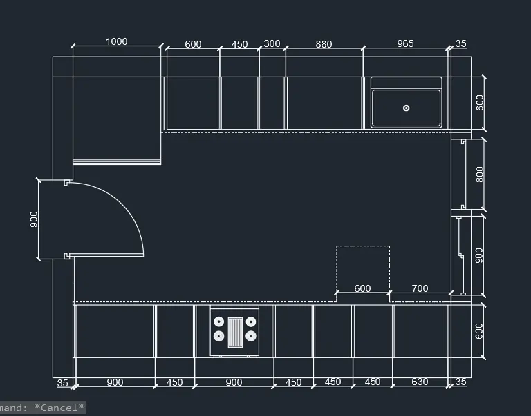
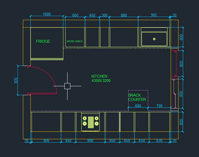
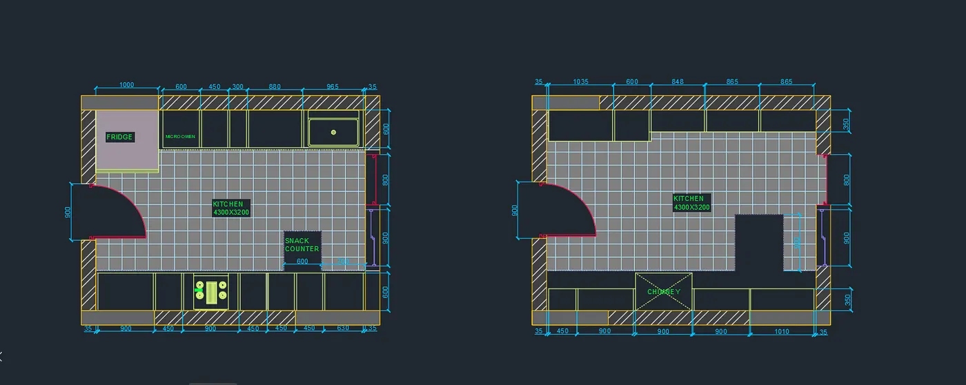
The kitchen plan is drawn with the help of the following AutoCAD tools.
PROCEDURE:
Open AutoCAD
Change units as per your required
Type UN in command box and press enter
change units type to decimal and precision to 0.00 and insrtion scale to mm next units type D in command box and press enter change DIMSTYLE as based on units
command used in this
UNITS COMMAND
DIMSTYLE COMMAND
LINE COMMAND
TRIME COMMAND
REC COMMAND
DIM COMMAND
OFFSET COMMAND
CIRCLE COMMAND
FILLET COMMAND
TEXT COMMAND
the outer of the kitchen plan are marked with the help of horizontal and vertical construction lines.
an offset of 230mm is drawn to mark the walls of the kitchen.
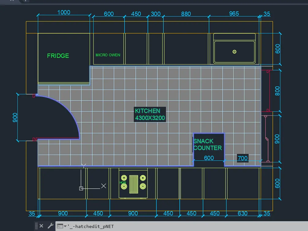
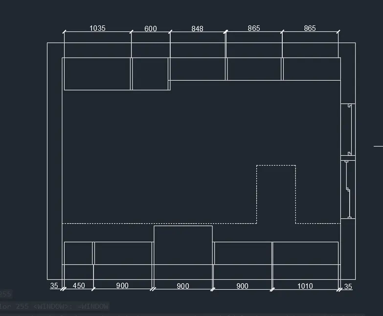
the counters in the kitchen is drawn with offset again and the required segments are created as per the dimensions.
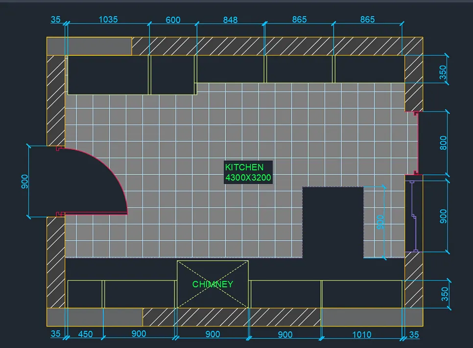
this is then copied to create the top part of the kitchen area the counter reions are edited as the dimensions.
the hatching is provided with the help of hatch command to mark the wall region.
the extra and unwanted lines are trimmed and deleted later.
 '
'
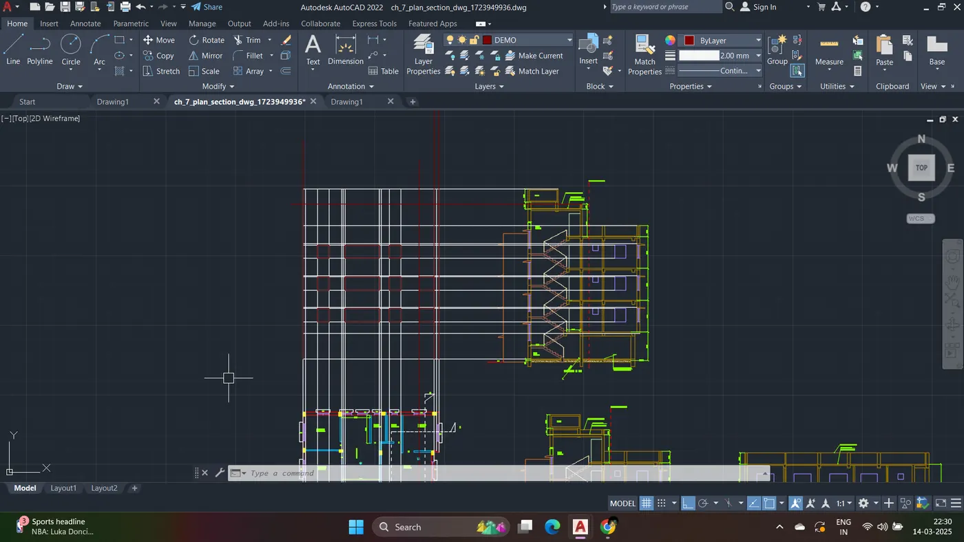
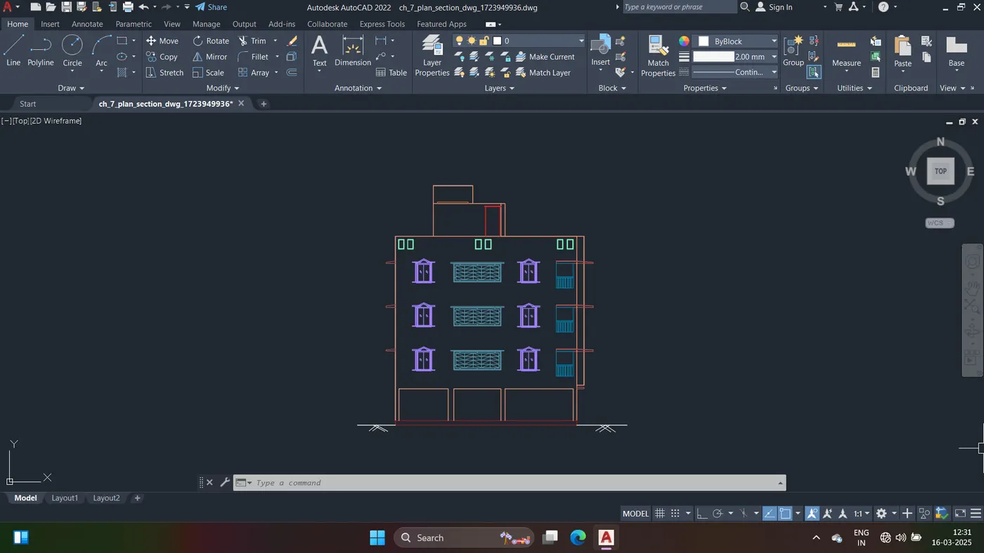
AIM: Create the elevation of the plan created in challenge 7.
INTRODUCTION: Create the elevation 7 and apply proper hatch in the walls, doors, windows and other architectural elements. refer to the dimensions in plans and sections in challenge 7.
PROCEDURE:
1. As per the challenge 7 plan by using lines command the elevation outer marks are created,
2.by using offsets walls are created,
3. created the window by using rectangle and line commands, make it back by using the block command,
4. but using insert command block inserted at specified locations,
5. at center architecture elevations created by using line and offset command,
6. after that the corner portion is created by using the rectangle command and array command,
7. finally the by using hatch command selected the hatch visible in plan specified the boundaries click enter,
8. the hatched portion copied for each portion.
result : created the elevation of the plan created in challenge 7 and applied proper hatch in the walls, doors, windows,
AIM : create the section view of an industrial building as shown in the figure.
INTRODUCTION:
create the section view of an industrial building as shown in the figure.
provide appropriate hatches and dimensions whenever required. also, provide annotations to the drawing.
PROCEDURE:
1. by using line command the outer view of industrial elevation is created,
2. by using the multiline command the walls and beams are created by varying the scale,
3. by using the offset the outer portions are created,
4. by using a rectangle the concrete portions are created,
5. by using the text command text is inserted,
6, by using the dim command the distance are measured,
7. by using the hatch command hatched happened by clicking hatch selected the hatch as concrete and attached the colour as grown and with a transparency of 40% click on enter.
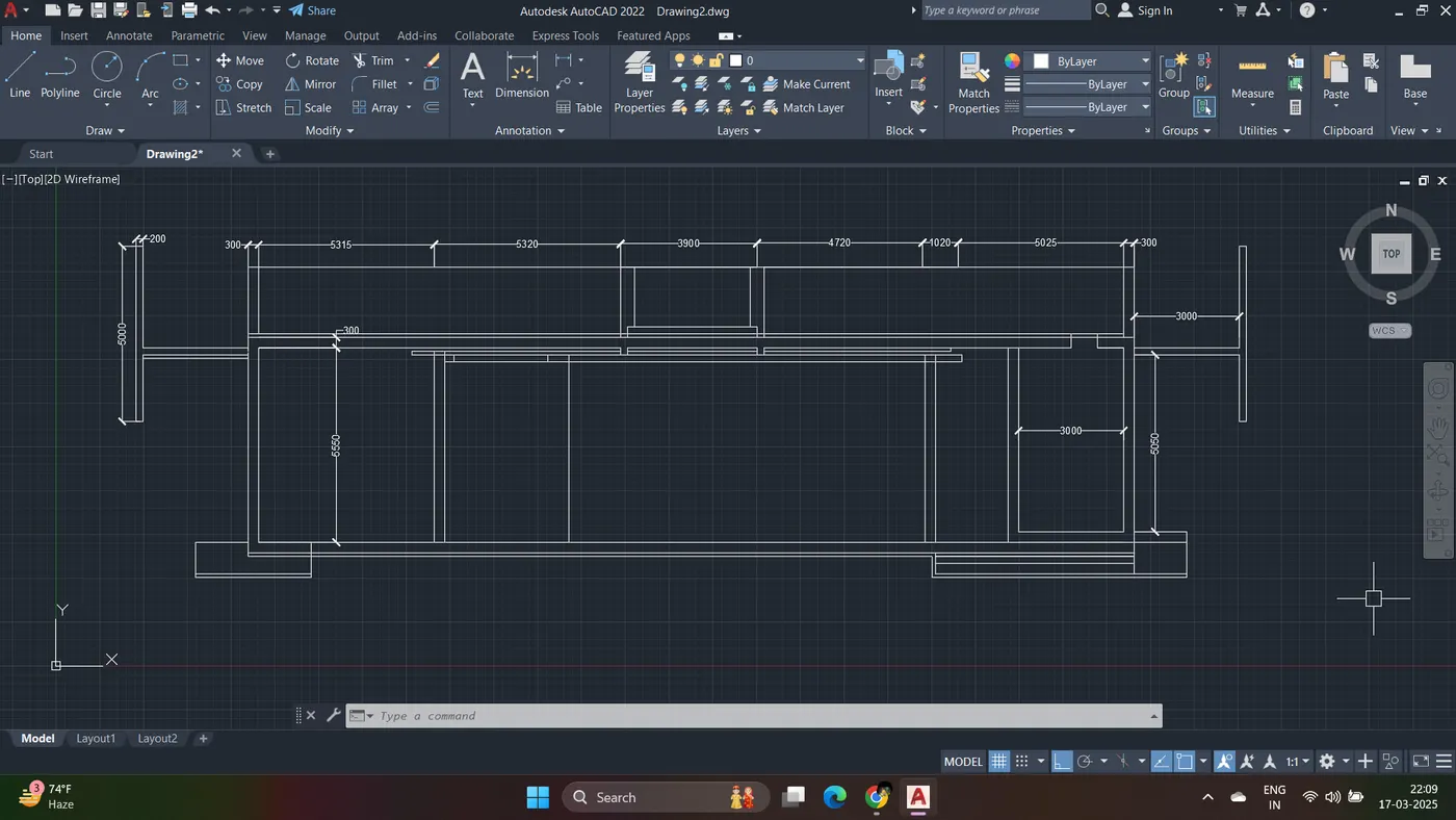
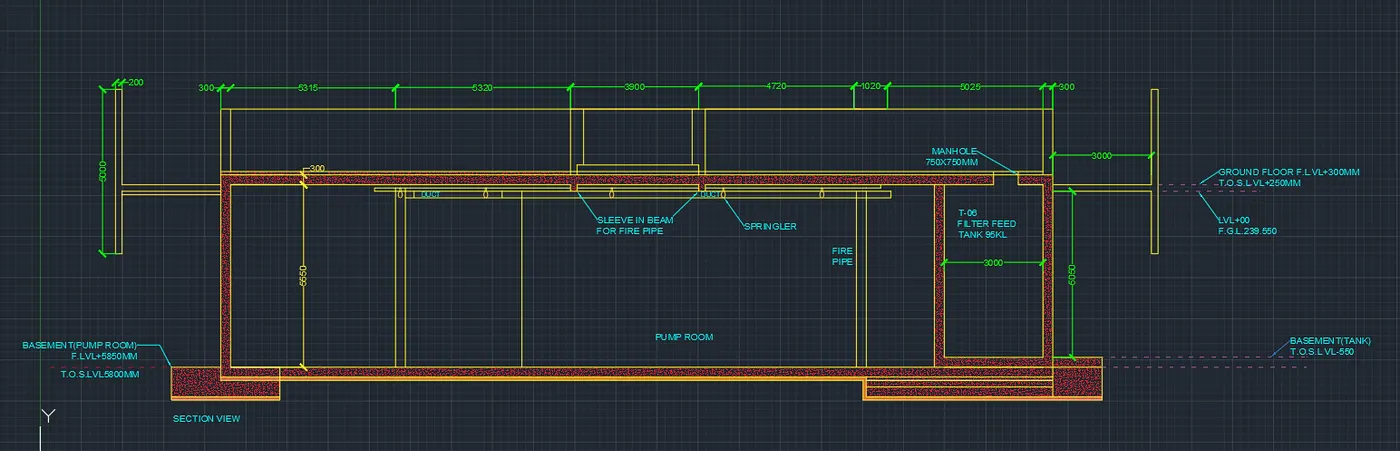
RESULT:
created the section view of an industrial building as shown in the figure. provided appropriate hatches and dimensions whenever required also provide annotations to the drawing.