Creating Kitchen layout, Hatching of Architectural elements and sectional view of an Industrial Building in AutoCad
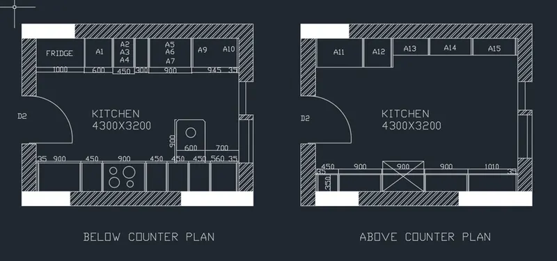
- Kitchen layout:
Aim: to draw the kitchen layout.
Procedure:
- First, we draw the Below counter plan:
- We create a wall by drawing a rectangle of 4300X3200mm and draw offsets of 230mm as wall thickness towards outside.
- Now we draw the Left cabinet and fridge:
- We draw the fridge by drawing a rectangle.
- Take an offset of 1000mm start drawing slab showing cabinet below.
- Offset 600mm for cabinet below for microwave oven and give an offset of 20mm.
- For width of cabinet give 600mm offset, give 20mm inside offset and 10mm offset for thickness.
- From 600mm offset give an offset of 450mm for A1.
- From that give 300mm offset for A2, A3, A4.
- From 300mm offset give another offset of 900mm for A5, A6, A7.
- Draw 35mm offset from the right side front the hinge and give thickness of 20mm.
- Now Drawing the right cabinets and hob:
- Give 35mm offset from the left and create a hinge.
- For width of cabinet give 600mm offset, give 20mm inside offset and 10mm offset for thickness.
- From 35mm give 900mm offset.
- Give an offset of 450mm from the 900mm offset and again offset a distance of 900mm.
- Offset a distance of 450mm three times from the previous offset.
- From the right side offset 35mm for hinge and rest distance will be 630mm which shows the top of cabinet.
- Hob is drawn by rectangle and circle tool in the plan of third cabinet.
- Draw the snack counter by giving offset distance of 700mm from the left side of wall and 900mm from the 600mm width of cabinet and fillet with 10m radius.
- Now draw the above counter plan:
- Copy the wall of the below counter plan.
- Draw the right side counter:
- Draw a width of 350mm from the wall to inside offset 20mm.
- Offset a distance of 35mm from the left side of wall.
- Now offset 450mm for the top of the cabinet.
- Offset 900mm 3 times for next cabinets.
- For the second 900mm offset, draw a rectangle distance of 1650mm from the left side of wall draw circle for the chimney.
- Now draw the left side counter:
- From the left side of wall take 35mm offset.
- Now draw 600mm offset as width from the horizontal wall.
- Draw 10mm offset to show the door.
- From the 35mm hinge offset 965mm to the right A11.
- From that offset 600mm for the next cabinet A12.
- Take offset distance of 35mm from the right.
- Rest distance is 2665mm wich is divided into 3 equal parts A13,A14,A15.
- Now offset 20mm on both sides of divisions and also 20mm in front for doors.
- Offset 10mm in backside for thickness.
- Create the Doors,sliding doors and windows:
- Door of size 900mm width and hinge of 20mm.
- Window of width 900mm.
- For the sliding doors take 200mm offset from the window and giving an opening of 900mm.
- Draw the shutters of the sliding door and copy in the other plan also.
- Insert the text by using multiline text of 75mm size and style-roman.shx.
- Dimension all the object using dimension tool bar.
Result: Kitchen layout is drawn.
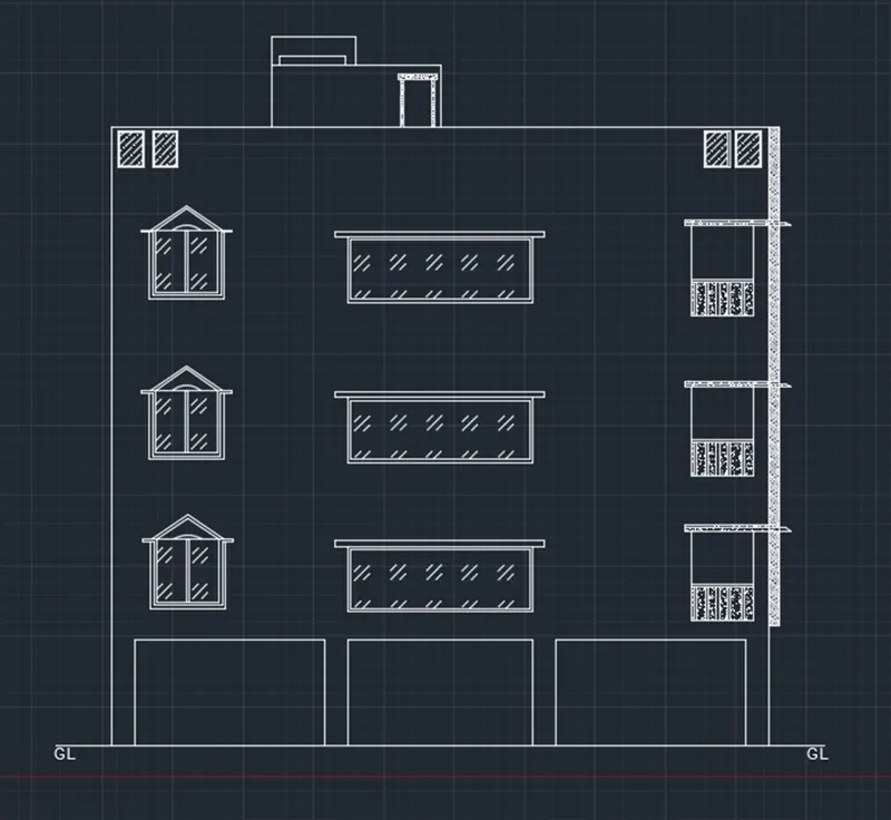
- Aim: to create the elevation of plan drawn in challenge 7.
Procedure:
- Open the Auto CAD
- Open the file of week & where plan is made.
- Extend the construction line from every wall, windows, staircase, ventilators chajja (elevation is from section BB).
- Trim the extra lines where lines are not required.
- Draw the frame of the window with the help of line and arc command.
- Type BL in the command prompt and select the frame.
- Select the point and name it as frame and save.
- From insert option insert the block and place it at every window.
- Select the hatch option select pattern and select the brick.
- Click at the wall where hatching is done.
- Select the door.
- Right click on the hatch properties then select the size of the hatch pattern.
- Elevation is obtained and hatch is done.
- Do the dimensioning wherever required.
- Using the multiline text insert the text the in the drawing.
Result: Elevation of plan is created in AutoCAD software using above mentioned procedure as shown below.
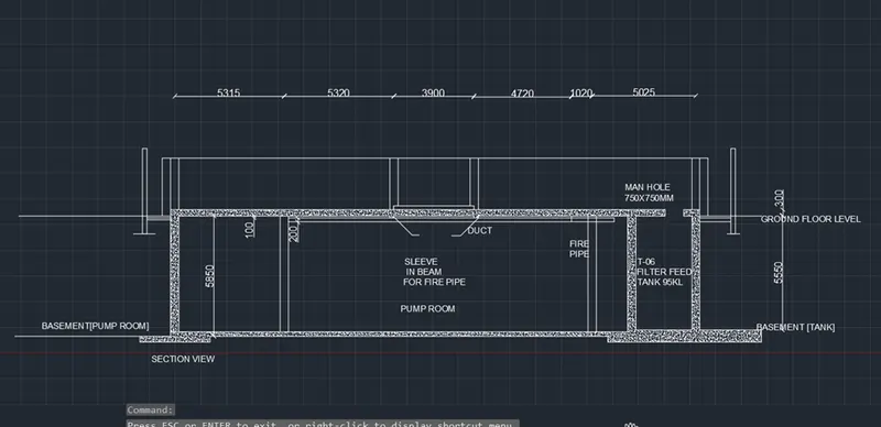
- Aim: To create the section view of an industrial building by providing hatches and dimensions in AutoCAD software.
Procedure:
- Type QNEW in command box, press enter, select the default setting as metric and select ok.
- Type UN in command box, press enter, select, measurement unit as decimal with the precision 0.
- Type XL in command box, press enter, draw the horizontal line.
- Type O in command box, press enter, specify offset distance 5850 units and take offset in upward direction.
- Similarly take offset of 300 units in the upward direction.
- Type XL in command box, press enter, select the vertical option from command box and draw the vertical line.
- Trim the extra projected line using trim tool.
- Type O in command box, press enter, specify offset distance 5315 units and take offset to the vertical line in right direction.
- Similarly take offset of 5320, 3900, 4720, 1020 and 5025 units in the same right direction to the just drawn vertical line.
- Type O in command box, press enter, specify offset distance 200 units and take offset to the first, second, sixth and seventh offset vertical line in right and left direction.
- Similarly draw the upper portion of section using line tool.
- Using the trim tool trim the extra portion of lines.
- Type O in command box, press enter, specify offset distance 2500 units and take offset to the second rightmost vertical line in left direction followed by offset of 400 units in the same direction.
- From the bottom horizontal line take offset of 300 units in downward direction.
- Type O in command box, press enter, specify offset distance 250 units and take offset to the same line in downward direction.
- Trim the extra projected lines using trim tool to crate the desired shape.
- Type O in command box, press enter, specify offset distance 50 units and take offset to the second top horizontal line in downward direction.
- Type O in command box, press enter, specify offset distance 100 units and take offset to the just drawn offset in downward direction.
- Similarly using the line tool draw the remaining pipes and trim the extra lines using trim tool.
- Type H in command box, press enter, select the AR-CONC as hatch pattern and fill the portion of section by picking internal point wherever required.
- For drawing the hidden line, in properties panel click on drop down of linetype, select other option and in line type manger dialog box, load the hidden line.
- Select the line which is required to convert into dotted lines and from properties panel select the loaded hidden line and convert it into hidden line.
- Using the match property tool convert the line wherever required into hidden line.
- ST in command box, press enter, select font name as Arial, with text height 250 units and select apply and ok.
- Type DIMLIN in command box, press enter, and give the dimensions to the lines wherever required.
- Type C in command box, press enter, and draw the circle.
- Type MTEXT in command box, press enter, specify first corner and opposite corner and type the text inside the circle such that to fit inside the circle.
- Type CO in command box, press enter, select the text within the circle along with the text and copy it to the required position.
- Type ED in command box, press enter, select the text and edit the text as per requirement.
- Type Qleader in command box, press enter, in leader line and annotation tab select the number of points as 3, select ok specify first, second and third leader points and type the text as per required content.
- In annotation tab, select the multileader option from leader panel and draw the leaders wherever required.
Result:
The section view of industrial building is created using the in AutoCAD software by following the above-mentioned procedure as shown below.