Creating Kitchen layout, Hatching of Architectural elements and sectional view of an Industrial Building in AutoCad
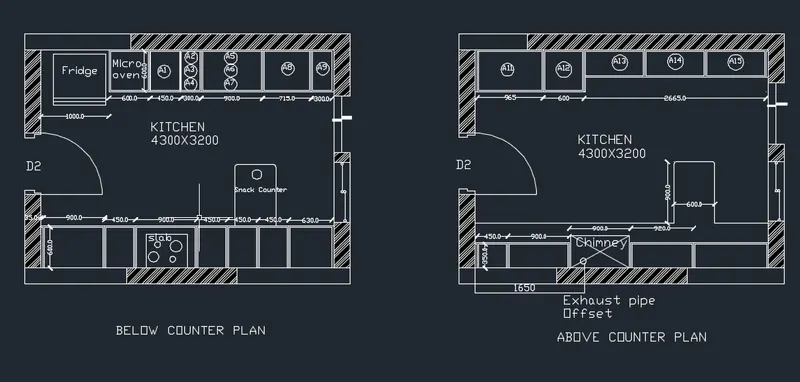
1. Kitchen layout:
Aim: to draw the kitchen layout.
Procedure:
- First we draw the Below counter plan:
- We create a wall by drawing a rectangle of 4300X3200mm and draw offsets of 230mm as wall thickness towards outside.
- Now we draw the Left cabinet and fridge:
- We draw the fridge by drawing a rectangle.
- Take an offset of 1000mm abd start drawing slab showing cabinet below.
- Offset 600mm for cabinet below for microwave oven and give an offset of 20mm.
- For width of cabinet give 600mm offset,give 20mm inside offset and 10mm offset for thickness.
- From 600mm offset give an offset of 450mm for A1.
- From that give 300mm offset for A2,A3,A4.
- From 300mm offset give another offset of 900mm for A5,A6,A7.
- Draw 35mm offset from the right side fro the hinge and give thickness of 20mm.
- Now Drawing the right cabinets and hob:
- Give 35mm offset from the left and create a hinge.
- For width of cabinet give 600mm offset,give 20mm inside offset and 10mm offset for thickness.
- From 35mm give 900mm offset.
- Give an offset of 450mm from the 900mm offset and again offset a distance of 900mm.
- Offset a distance of 450mm three times from the previous offset.
- From the right side offset 35mm for hinge and rest distance will be 630mm which shows the top of cabinet.
- Hob is drawn by rectangle and circle tool in the plan of thrid cabinet.
- Draw the snack counter by giving offset distance of 700mm from the left side of wall and 900mm from the 600mm width of cabinet and fillet with 10m radius.
- Now draw the above counter plan:
- Copy the wall of the below counter plan.
- Draw the right side counter:
- Draw a width of 350mm from the wall to inside offset 20mm.
- Offset a distance of 35mm from the left side of wall.
- Now offset 450mm for the top of the cabinet.
- Offset 900mm 3 times for next cabinets.
- For the second 900mm offset,draw a rectangle anf froma distance of 1650mm from the left side of wall.draw circle for the chimney.
- Now draw the left side counter:
- From the left side of wall take 35mm offset.
- Now draw 600mm offset as width from the horizontal wall.
- Draw 10mm offset to show the door.
- From the 35mm hinge offset 965mm to the right A11.
- From that offset 600mm for the next cabinet A12.
- Take offset distance of 35mm from the right.
- Rest distance is 2665mm wich is divided into 3 equal parts A13,A14,A15.
- Now offset 20mm on both sides of divisions and also 20mm in front for doors.
- Offset 10mm in backside for thickness.
- Create the Doors,sliding doors and windows:
- Door of size 900mm width and hinge of 20mm.
- Window of width 900mm.
- For the sliding doors take 200mm offset from the window and giving an opening of 900mm.
- Draw the shutters of the sliding door and copy in the other plan also.
- Insert the text by using multiline text of 75mm size and style-roman.shx.
- Dimension all the object using dimension tool bar.
Result: Kitchen layout is drawn.
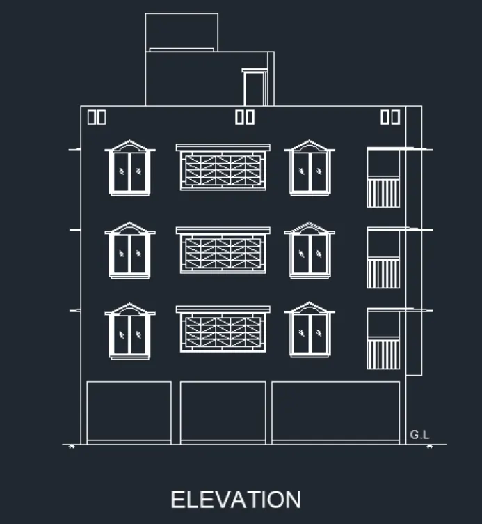
Aim: to create the elevation of plan drawn in challenge 7.
Procedure:
- Open the Auto CAD
- Open the file of week & where plan is made.
- Extend the constrcution line from every wall,windows,staircase,ventilators chajja(elevation is from section BB).
- Trim the extra lines where lines are not required.
- Draw the frame of the window with the help of line and arc command.
- Type BL in the command prompt and select the frame.
- Select the point and name it as frame and save.
- From insert option insert the block and place it at every window.
- Select the hatch option select pattern and select the brick.
- Click at the wall where hatching is done.
- Select the door.
- Right click on the hatch properties then select the size of the hatch pattern.
- Elevation is obtained and hatch is done.
- Do the dimensioning wherever required.
- Using the multiline text insert the text the in the drawing.
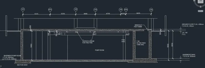
3. Aim: to draft the section view of industrial building plan and hatching it using AutoCAD.
Procedure:
- Open Auto CAD.
- Type UN in command prompt and select decimal and precision 0.
- Type Limits in command promt and specify the lower and upper points.
- Z enter a enter now we are ready for the drafting.
- Draw a line with ortho on 25300 in x direction.
- Draw a line with ortho on 5850 in y direction.
- Type offset and do the offset as 230 and select the line left side of vertical line.
- Draw a line in x direction 25300 with top line.
- Type offset and do the offset of 300.
- Draw a line in x direction 25300 with top line.
- Type offset and do the offset of 300.
- Draw a line in vertical and do offset of 200.
- Type offset and do offset of 300 horizontal line for duct.
- Type offset and do offset of 200 from bottom horizontal line for duct.
- Type offset and do offset of 100 from top line for sleeve sprayer.
- Trim all the extra lines with trim command and join all the lines.
- Select the point at lower left and type @1000<180.
- Now type @500<270,@2000<0,@3300<90,@17055<0,@300<270,@5045<0,@500<90,@300<270,@5850<90.
- Type offset and fo offset of 230.
- Join all the missing lines and trim the extra lines.
- Select the hatch command and go to pattern and select concrete and do the hatching wherever required.
- Select the line command and draw the sprayer.
- Select the leader command and select the sprayer and make as block and insert the block wherever needed.
- Do the dimension of follwing using dimension command in command prompt.
- Insert the circle and copy and paste wherver required.
- Do the finishing by joining all the lines.
Result: