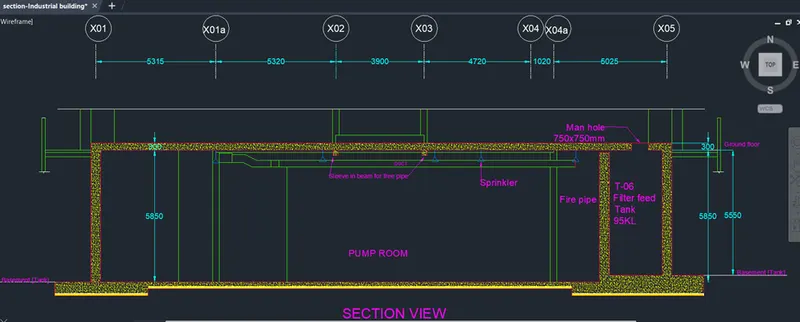
Creating Kitchen layout, Hatching of Architectural elements and sectional view of an Industrial Building in AutoCad
- The kitchen layout:
Aim:
To create the kitchen layout using Auto CAD.
Introduction:
The following commands and tools are used in this Auto CAD drawing,
- Line: It helps to create a line between two points
- Rectangle: It helps to create a four-sided geometry with a desired length and width.
- Offset: It helps to offset an object at a particular distance.
- Move: It helps to move an already existing object from one point to the other by picking a base point.
- Copy: It helps to copy an already existing object from one point to the other by picking a base point.
- Trim: It helps to trim off the extra lines or objects of a selected object which is created while using other tools.
- Break at point: It helps to break the selected object at a single point
- Erase: It helps to erase a selected object.
- Hatch: It helps to hatch a select closed objects in different patterns
- DT: single text: It helps to enter the single line text
- MT: Multi-line text: It helps to type multi line text or paragraphs
- MTEXTED: Text edit: It helps to edit the typed texted.
- Blocks: It helps to create a set of different objects in to a single object and can be inserted easily in the plans
- Layers: It helps to create layers for each object according to its property by giving its line weight, color and line type.
Note:
- Keep Ortho on and Object snap on which are in the status bar throughout the drawing which helps to find midpoint, center point and so on.
Procedure:
- In command: units
- The drawing units dialog box appears, in that select Decimal as type and precision as 0.00, intersection scale as millimeters and click OK.
- In command: limits
- Specify lower left corner: 0.00,0.00
- Specify upper right corner: 10000,10000
- Enter zoom and enter all in the command.
- Select rectangle command and type dimension, length as 4300, width as 3200 and create 2 rectangles as Below counter plan and Above counter plan
- Select offset and give dimension as 230 and offset outside the rectangle on both.
- Select Break at point and break the lines at all the 4 corners of both rectangles.
- In both rectangles select the top and bottom horizontal lines, enter o and give offset distance as 600, 600, 600and 350 for the below- above counter plan respectively
- Select Break at point and break the lines at all the intersection point between horizontal offset and wall on both rectangles.
- Enter O and select the bottom left vertical line which used for break at point and give offset distance as 35 at below counter plan
- Enter O and select the previously created offset line and give offset distance as 900
- Enter O and select the previously created offset line and give offset distance as 450
- Enter O and select the previously created offset line and give offset distance as 900
- Enter O and select the previously created offset line and give offset distance as 450
- Enter O and select the previously created offset line and give offset distance as 450
- Enter O and select the previously created offset line and give offset distance as 450
- Enter O and select the previously created offset line and give offset distance as 560
- Enter O and select the previously created offset line and give offset distance as 35
- Enter O and select the previously created offset line and give offset distance as 900
- Enter O and select the other half line on right broken line and give offset distance as 700
- Enter O and select the previously created offset line and give offset distance as 600 like shown below
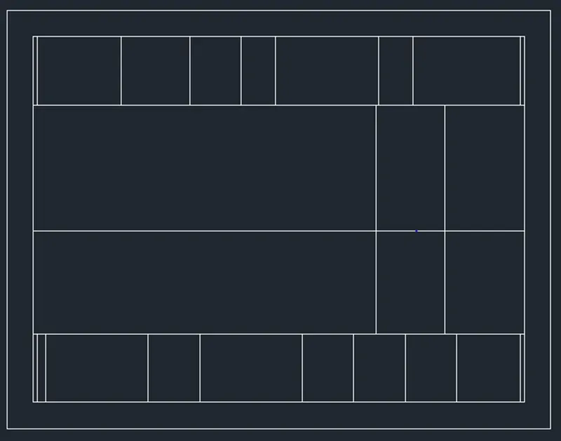
- Enter O and select the top right vertical line which used for break at point and give offset distance as 35
- Enter O and select the previously created offset line and give offset distance as 945
- Enter O and select the previously created offset line and give offset distance as 300
- Enter O and select the previously created offset line and give offset distance as 900
- Enter O and select the previously created offset line and give offset distance as 300
- Enter O and select the previously created offset line and give offset distance as 450
- Enter O and select the previously created offset line and give offset distance as 600
- Enter O and select the previously created offset line and give offset distance as 735
- Enter O and select the previously created offset line and give offset distance as 35
- Enter O and select the bottom left vertical line which used for break at point and give offset distance as 35 at above counter plan
- Enter O and select the previously created offset line and give offset distance as 450
- Enter O and select the previously created offset line and give offset distance as 900
- Enter O and select the previously created offset line and give offset distance as 35
- Enter O and select the previously created offset line and give offset distance as 900
- Enter O and select the previously created offset line and give offset distance as 35
- Enter O and select the previously created offset line and give offset distance as 900
- Enter O and select the previously created offset line and give offset distance as 1010
- On top select the top left vertical line which used for break at point and give offset distance as 35 at above counter plan
- Enter O and select the previously created offset line and give offset distance as 965
- Enter O and select the previously created offset line and give offset distance as 600
- Enter O and select the previously created offset line and give offset distance as 865 and often for 2 more times
- Enter O and select the top horizontal line and give offset distance as 350 as shown below
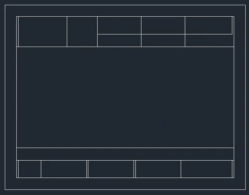
- Select line command and create a door outside the plan
- Create block for door by entering b, which displays the Block definition dialog box. As per the dialog box pick a point and select the object as this above created door and other setting as shown below
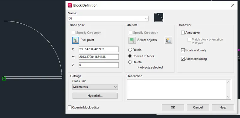
- Select copy command and place it in the middle point of both the plans
- In both counter plans select all the inner lines and give offset distance as 30 on both sides of the lines
- Select Trim and trim all the excess lines in the below counter plan
- Select the snack counter lines and change its line type to dotted line by right clicking to open the properties
- Using line command create windows as shown below
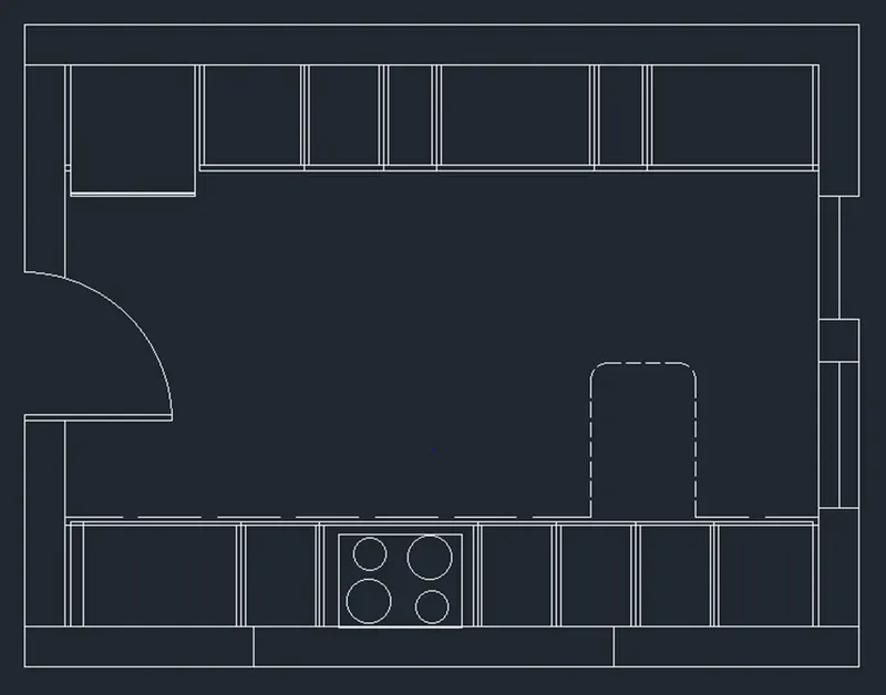
- Select the copy command and select the windows and dotted lines from snack counter and pick the base point and copy it to the above counter plan
- Select trim and select whole object and trim all the excess lines as shown below
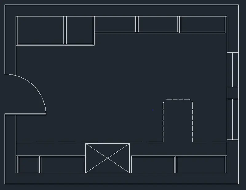
- Enter h and select the below setting and give hatches on both the plans by pick the point.

- Select layer properties and create layers as follow
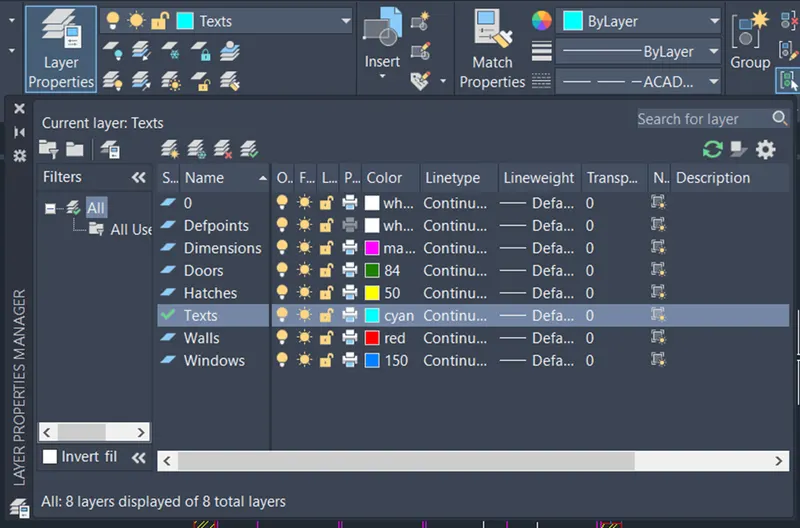
- After selecting text layer
- Enter Dt for single line text and MT for multi-layer text.
- Select Dimension layer and select linear and continuous dimension for respective length of dimension
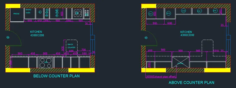
Result:
- The result is obtained from the above procedure.
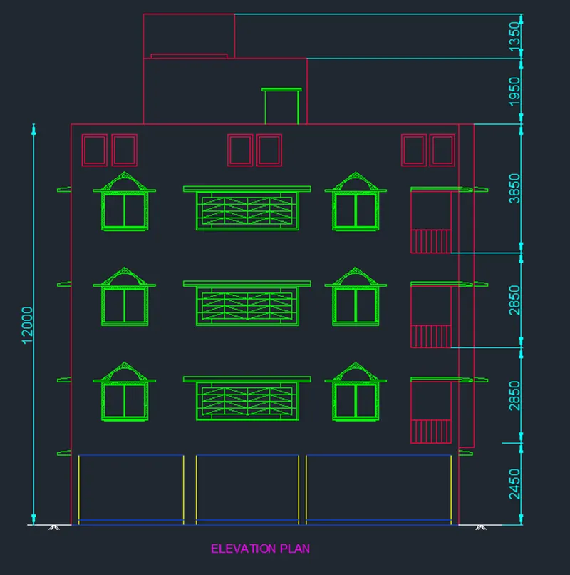
2.The Elevation of the plan:
Aim:
To create the elevation of the plan created in the challenge 7 using Auto CAD.
Introduction:
The following commands and tools are used in this Auto CAD drawing,
- Xl: It is the construction line which has infinite length which helps to extend the line of a plan or to create a plan
- Line: It helps to create a line between two points
- Rectangle: It helps to create a four-sided geometry with a desired length and width.
- Offset: It helps to offset an object at a particular distance.
- Move: It helps to move an already existing object from one point to the other by picking a base point.
- Copy: It helps to copy an already existing object from one point to the other by picking a base point.
- Trim: It helps to trim off the extra lines or objects of a selected object which is created while using other tools.
- Break at point: It helps to break the selected object at a single point
- Erase: It helps to erase a selected object.
- Hatch: It helps to hatch a select closed objects in different patterns
- DT: single text: It helps to enter the single line text
- MT: Multi-line text: It helps to type multi line text or paragraphs
- MTEXTED: Text edit: It helps to edit the typed texted.
- Blocks: It helps to create a set of different objects in to a single object and can be inserted easily in the plans
- Layers: It helps to create layers for each object according to its property by giving its line weight, color and line type.
Note:
- Keep Ortho on and Object snap on which are in the status bar throughout the drawing which helps to find midpoint, center point and so on.
Procedure:
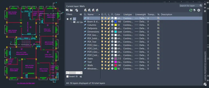
- Open the Challenge 7 AutoCAD file which created with layers earlier as shown below
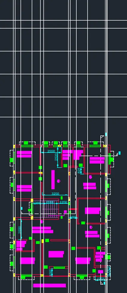
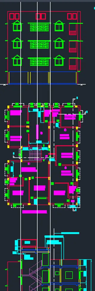
- Using xl vertical line and extend the lines of columns and windows and with xl horizontal line create 3 floors and parapet wall those dimensions are taken from session plan as shown below
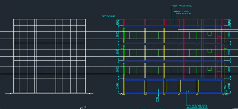
- Using copy and rotate command select the sectional plan parallel to elevation plan
- Enter XL and extend the balcony and sill and lintel level as shown below
- Enter Tr and trim all the excessive line off the elevation plan
- Select copy command and copy the sunshade which created earlier and place it as required.
- Using rec and offset create a rectangle on the left corner of the parapet wall
- Enter co and select the rectangle which created above as paste as shown below
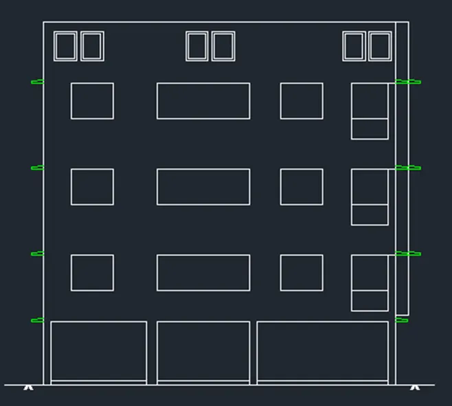
- Using line, offset and hatch command create the windows as shown below
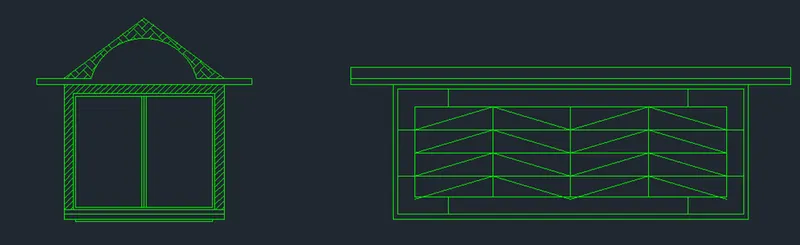
- Change all lines according to its layer
- Enter co and copy the window created above and place it as shown below
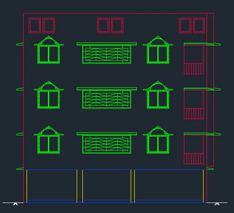
- Enter XL and V and extend the upper projected portion of vertical line in SECTION-AA to the ELEVATION PLAN for temporary reference line.
- Select copy command and select the O.H.T , parapet wall above the 3rd floor lintel level and pick the left intersection point of the xl vertical line as base point and place it in the same point of the elevation plan as shown below
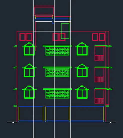
- Enter TR and trim all the excessive lines as shown below
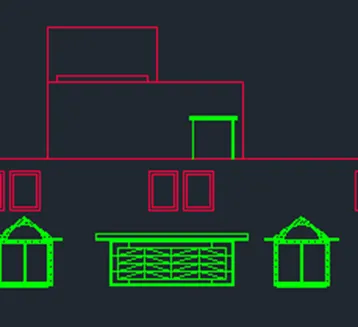
- Give dimension and text using its appropriate layers which created earlier.
Results:
- The result is obtained from the above procedure.
- The section view of the industrial building:
Aim:
To create the section view of the industrial building using Auto CAD.
Introduction:
The following commands and tools are used in this Auto CAD drawing,
- Line: It helps to create a line between two points
- Rectangle: It helps to create a four-sided geometry with a desired length and width.
- Offset: It helps to offset an object at a particular distance.
- Move: It helps to move an already existing object from one point to the other by picking a base point.
- Copy: It helps to copy an already existing object from one point to the other by picking a base point.
- Trim: It helps to trim off the extra lines or objects of a selected object which is created while using other tools.
- Break at point: It helps to break the selected object at a single point
- Erase: It helps to erase a selected object.
- Hatch: It helps to hatch a select closed objects in different patterns
- DT: single text: It helps to enter the single line text
- MT: Multi-line text: It helps to type multi line text or paragraphs
- MTEXTED: Text edit: It helps to edit the typed texted.
- Blocks: It helps to create a set of different objects in to a single object and can be inserted easily in the plans
- Layers: It helps to create layers for each object according to its property by giving its line weight, color and line type.
Note:
- Keep Ortho on and Object snap on which are in the status bar throughout the drawing which helps to find midpoint, center point and so on.
Procedure:
- In command: units
- The drawing units dialog box appears, in that select Decimal as type and precision as 0.00, intersection scale as millimeters and click OK.
- In command: limits
- Specify lower left corner: 0.00,0.00
- Specify upper right corner: 50000,50000
- Enter zoom and enter all in the command.
- Select xl and choose v and place a xline on workspace.
- Enter o and select the above xline and give offset distance as 5315,5320,3900,4720,1020,5025 one by one to create offset lines as grid lines.
- Create a horizontal base line and other lines using offset toots with random dimension as shown below.
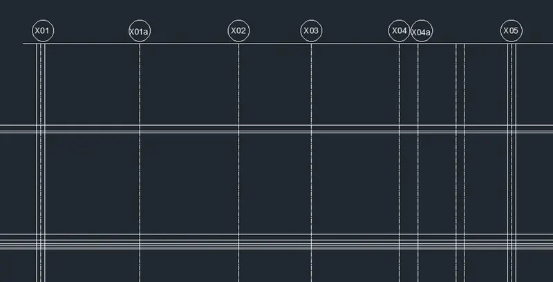
- Use trim command to trim all the excess lines
- Use offset and line commands with the dimension given in the section plan and some with random dimension create the below plan
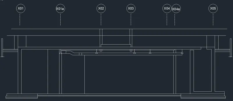
- Enter h and use the below settings to hatch

- Hatch the proportion as shown below
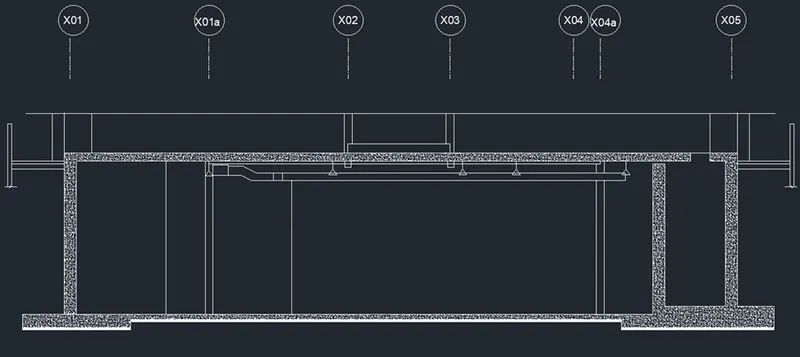
- Use DT, MT and dimension command to enter the text and to give dimension as per the drawing
- Create layer using layer properties as shown below
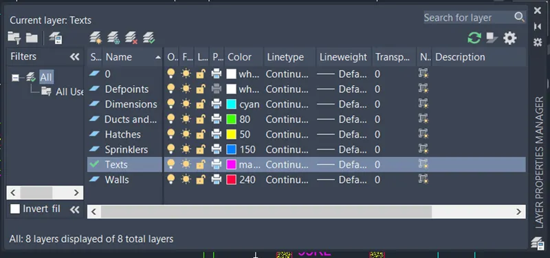
- Layer all the objects as per the properties
Results:
- The result is obtained from the above procedure.