Creating Kitchen layout, Hatching of Architectural elements and sectional view of an Industrial Building in AutoCad
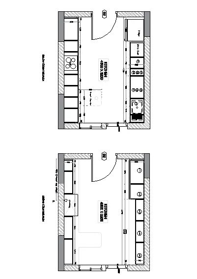
1. Creating the Kitchen Layout and providing hatch pattern as shown in the figure:
Aim:
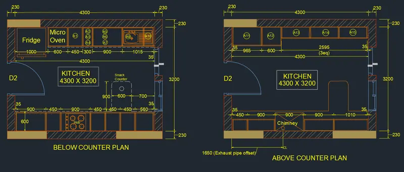
- To draw the kitchen layout and provide the hatch pattern as shown in the figure above, in AutoCAD.
Introduction:
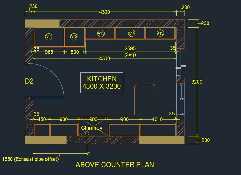
- The kitchen layout is created in AutoCAD using primarily the Rectangle and Line tools and after sketching, the objects, dimensions and texts and hatches are provided. The procedure of drawing is explained in detail with diagrams of each step and the final result is given.
Procedure:
STEP 1
- Go to START MENU, select AutoCAD 2022.
- In the Command line type in: STARTUP [ENTER]
- Enter new value of startup: 1
- Go to Application Menu and select New
- In the Startup dialog box set Metric as the default settings.
- In the Advanced Setup and select the 'Decimal' unit of measurement and select precision as ' 0 '.
- Set the limits by entering LIMITS in the Command tab. The lower-left corner is specified as 0,0; and the upper-right corner is specified as 10000,10000.
- Enter 'UNITS' command in the command tab.
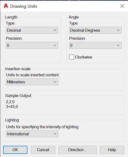
- In the Drawing Units dialog box, select 'Decimal' in Type; ' 0 ' in Precision; and 'Millimeters' in Insertion scale.
- Click on 'OK'.
STEP 2
- Click on 'Layer Properties' in the Layer panel on the Ribbon.
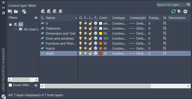
- Click on 'New Layer' to create the following layers - Doors and windows; Walls; Furniture and fittings; Hatch and Dimension and Text.
- Specify different colors for the different layers and then close the Layer Properties Manager dialog box.
STEP 3
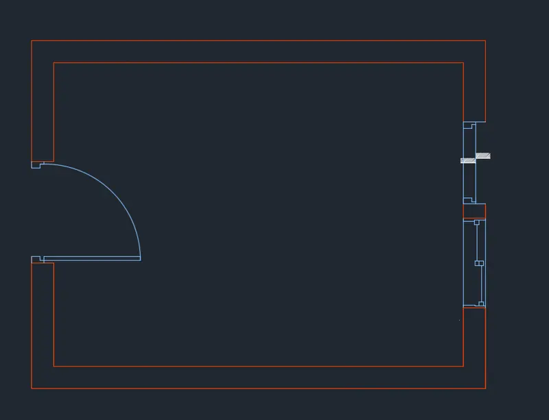
- Set current the Walls layer.
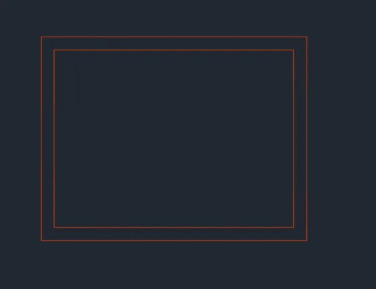
- Select the Rectangle tool by entering ‘REC’ command in the command tab.
- Specify the first point.
- Select Dimensions option in the command line.
- Specify length of rectangle as 4760 in the command line.
- Specify width of rectangle as 3660 in the command line.
- Move the cursor towards the upward and click ENTER.
- Select the Offset tool by entering ‘OFFSET’ command in the command tab.
- As thickness of external wall is 230, enter 230 as offset distance in the command line.
- Select both the rectangle created before.
- Click on the inside to offset.
- Press Esc.
STEP 4
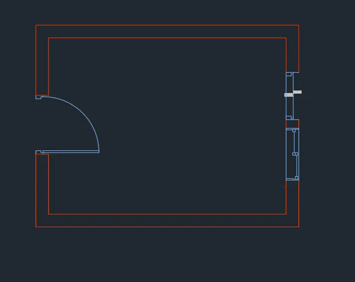
- Set current the doors and windows layer.
- Select the Line tool by entering ‘LINE’ command in the command tab.
- Specify the start point.
- Draw door at the specified positions.
- Door is created with a width of 1000.
- Press Esc to cancel the LINE command.
- Selet the Arc tool from the ribbon, choose the Start, End, Direction option, then draw an arc to represent the swing of the door by specifying the start, end and direction of the arc as suitable.
- Select the Line tool by entering ‘LINE’ command in the command tab.
- Draw the door frame.
- Press Esc.
- Select the Line tool by entering ‘LINE’ command in the command tab.
- Specify the start point.
- Draw window at the specified positions.
- Window is created with a width of 900.
- Press Esc to cancel the LINE command.
- Select the Line tool by entering ‘LINE’ command in the command tab.
- Draw the Window frame.
- Press Esc.
- Select the Line tool by entering ‘LINE’ command in the command tab.
- Create an opening of width 850.
- Draw the frame of the opening.
- Press Esc.
- Select the Trim tool by entering ‘TR’ command in the command tab.
- Press ENTER.
- Select Edge option; and click on No Extend.
- Select the extruted lines.
- Press ‘Esc’ to cancel the TRIM command.
- Enter B in the command promt.
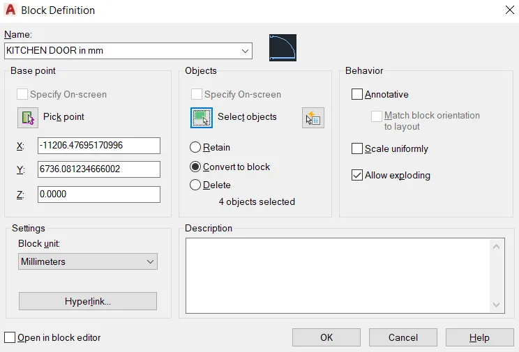
- In the Block Definition dialogue box, type in the name of the block as KITCHEN DOOR in mm, pick point as the bottom right edge of the door, Select the object created and press Enter.
- Click OK.
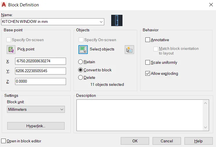
- In the Block Definition dialogue box, type in the name of the block as KITCHEN WINDOW in mm, pick point as the bottom right edge of the door, Select the object created and press Enter.
- Click OK.
STEP 5
- Set current the furniture and fittings layer.
- Select the Line tool by entering ‘LINE’ command in the command tab.
- Specify the start point.
- Draw a line joining the inner edges of the kitchen wall, press Esc.
- Select the line, right click, go to properties and change the line type to ISO dash.
- Select the Rectangle tool by entering ‘REC’ command in the command tab.
- Specify the first point at the inner edge of the .
- Select Dimensions option in the command line.
- Specify length of rectangle as 35 in the command line.
- Specify width of rectangle as 50 in the command line.
- Move the cursor towards the upward and click ENTER.
- Select the Rectangle tool by entering ‘REC’ command in the command tab.
- Specify the first point at the inner edge of the .
- Select Dimensions option in the command line.
- Specify length of rectangle as 900 in the command line.
- Specify width of rectangle as 560 in the command line.
- Move the cursor towards the upward and click ENTER.
- Select the rectangle and click on the Explode icon in the Ribbon.
- Select the Offset tool by entering ‘OFFSET’ command in the command tab.
- Specify offset distance as 20.
- Offset the top, right and left sides of the rectangle.
- Repeat offset, specify offset distance as 10.
- Offset the bottom edge of the rectangle
- Press Esc.
- Select the Rectangle tool by entering ‘REC’ command in the command tab.
- Specify the first point at the inner edge of the .
- Select Dimensions option in the command line.
- Specify length of rectangle as 450 in the command line.
- Specify width of rectangle as 560 in the command line.
- Move the cursor towards the upward and click ENTER.
- Select the rectangle and click on the Explode icon in the Ribbon.
- Select the Offset tool by entering ‘OFFSET’ command in the command tab.
- Specify offset distance as 20.
- Offset the top, right and left sides of the rectangle.
- Repeat offset, specify offset distance as 10.
- Offset the bottom edge of the rectangle
- Press Esc.
- Select the Rectangle tool by entering ‘REC’ command in the command tab.
- Specify the first point at the inner edge of the .
- Select Dimensions option in the command line.
- Specify length of rectangle as 900 in the command line.
- Specify width of rectangle as 560 in the command line.
- Move the cursor towards the upward and click ENTER.
- Select the rectangle and click on the Explode icon in the Ribbon.
- Select the Offset tool by entering ‘OFFSET’ command in the command tab.
- Specify offset distance as 20.
- Offset the top, right and left sides of the rectangle.
- Repeat offset, specify offset distance as 10.
- Offset the bottom edge of the rectangle
- Press Esc.
- Select the Rectangle tool by entering ‘REC’ command in the command tab.
- Specify the first point at the inner edge of the .
- Select Dimensions option in the command line.
- Specify length of rectangle as 450 in the command line.
- Specify width of rectangle as 560 in the command line.
- Move the cursor towards the upward and click ENTER.
- Select the rectangle and click on the Explode icon in the Ribbon.
- Select the Offset tool by entering ‘OFFSET’ command in the command tab.
- Specify offset distance as 20.
- Offset the top, right and left sides of the rectangle.
- Repeat offset, specify offset distance as 10.
- Offset the bottom edge of the rectangle
- Press Esc.
- Select the Rectangle tool by entering ‘REC’ command in the command tab.
- Specify the first point at the inner edge of the .
- Select Dimensions option in the command line.
- Specify length of rectangle as 450 in the command line.
- Specify width of rectangle as 560 in the command line.
- Move the cursor towards the upward and click ENTER.
- Select the rectangle and click on the Explode icon in the Ribbon.
- Select the Offset tool by entering ‘OFFSET’ command in the command tab.
- Specify offset distance as 20.
- Offset the top, right and left sides of the rectangle.
- Repeat offset, specify offset distance as 10.
- Offset the bottom edge of the rectangle
- Press Esc.
- Select the Rectangle tool by entering ‘REC’ command in the command tab.
- Specify the first point at the inner edge of the .
- Select Dimensions option in the command line.
- Specify length of rectangle as 450 in the command line.
- Specify width of rectangle as 560 in the command line.
- Move the cursor towards the upward and click ENTER.
- Select the rectangle and click on the Explode icon in the Ribbon.
- Select the Offset tool by entering ‘OFFSET’ command in the command tab.
- Specify offset distance as 20.
- Offset the top, right and left sides of the rectangle.
- Repeat offset, specify offset distance as 10.
- Offset the bottom edge of the rectangle
- Press Esc.
- Select the Rectangle tool by entering ‘REC’ command in the command tab.
- Specify the first point at the inner edge of the .
- Select Dimensions option in the command line.
- Specify length of rectangle as 560 in the command line.
- Specify width of rectangle as 560 in the command line.
- Move the cursor towards the upward and click ENTER.
- Select the rectangle and click on the Explode icon in the Ribbon.
- Select the Offset tool by entering ‘OFFSET’ command in the command tab.
- Specify offset distance as 20.
- Offset the top, right and left sides of the rectangle.
- Repeat offset, specify offset distance as 10.
- Offset the bottom edge of the rectangle
- Press Esc.
- Select the Trim tool by entering ‘TR’ command in the command tab.
- Press ENTER.
- Select Edge option; and click on No Extend.
- Trim the unwanted portion of lines.
- Press ‘Esc’ to cancel the TRIM command.
- Select the Line tool by entering ‘LINE’ command in the command tab.
- Specify the start point.
- Draw a line joining the top inner edges of the kitchen wall, press Esc.
- Select the line, right click, go to properties and change the line type to ISO dash.
- Select the Rectangle tool by entering ‘REC’ command in the command tab.
- Specify the first point at the top right inner edge of the .
- Select Dimensions option in the command line.
- Specify length of rectangle as 35 in the command line.
- Specify width of rectangle as 50 in the command line.
- Move the cursor towards the upward and click ENTER.
- Select the Rectangle tool by entering ‘REC’ command in the command tab.
- Specify the first point at the inner edge of the .
- Select Dimensions option in the command line.
- Specify length of rectangle as 300 in the command line.
- Specify width of rectangle as 560 in the command line.
- Move the cursor towards the upward and click ENTER.
- Select the rectangle and click on the Explode icon in the Ribbon.
- Select the Offset tool by entering ‘OFFSET’ command in the command tab.
- Specify offset distance as 20.
- Offset the bottom, right and left sides of the rectangle.
- Repeat offset command, specify offset distance as 10.
- Offset the top edge of the rectangle
- Press Esc.
- Select the Rectangle tool by entering ‘REC’ command in the command tab.
- Specify the first point at the inner edge of the .
- Select Dimensions option in the command line.
- Specify length of rectangle as 640 in the command line.
- Specify width of rectangle as 560 in the command line.
- Move the cursor towards the upward and click ENTER.
- Select the rectangle and click on the Explode icon in the Ribbon.
- Select the Offset tool by entering ‘OFFSET’ command in the command tab.
- Specify offset distance as 20.
- Offset the bottom, right and left sides of the rectangle.
- Repeat offset, specify offset distance as 10.
- Offset the top edge of the rectangle
- Press Esc.
- Select the Rectangle tool by entering ‘REC’ command in the command tab.
- Specify the first point at the inner edge of the .
- Select Dimensions option in the command line.
- Specify length of rectangle as 900 in the command line.
- Specify width of rectangle as 560 in the command line.
- Move the cursor towards the upward and click ENTER.
- Select the rectangle and click on the Explode icon in the Ribbon.
- Select the Offset tool by entering ‘OFFSET’ command in the command tab.
- Specify offset distance as 20.
- Offset the bottom, right and left sides of the rectangle.
- Repeat offset, specify offset distance as 10.
- Offset the top edge of the rectangle
- Press Esc.
- Select the Rectangle tool by entering ‘REC’ command in the command tab.
- Specify the first point at the inner edge of the .
- Select Dimensions option in the command line.
- Specify length of rectangle as 300 in the command line.
- Specify width of rectangle as 560 in the command line.
- Move the cursor towards the upward and click ENTER.
- Select the rectangle and click on the Explode icon in the Ribbon.
- Select the Offset tool by entering ‘OFFSET’ command in the command tab.
- Specify offset distance as 20.
- Offset the bottom, right and left sides of the rectangle.
- Repeat offset, specify offset distance as 10.
- Offset the top edge of the rectangle
- Press Esc.
- Select the Rectangle tool by entering ‘REC’ command in the command tab.
- Specify the first point at the inner edge of the .
- Select Dimensions option in the command line.
- Specify length of rectangle as 450 in the command line.
- Specify width of rectangle as 560 in the command line.
- Move the cursor towards the upward and click ENTER.
- Select the rectangle and click on the Explode icon in the Ribbon.
- Select the Offset tool by entering ‘OFFSET’ command in the command tab.
- Specify offset distance as 20.
- Offset the top, right and left sides of the rectangle.
- Repeat offset, specify offset distance as 10.
- Offset the bottom edge of the rectangle
- Press Esc.
- Select the Rectangle tool by entering ‘REC’ command in the command tab.
- Specify the first point at the inner edge of the .
- Select Dimensions option in the command line.
- Specify length of rectangle as 600 in the command line.
- Specify width of rectangle as 560 in the command line.
- Move the cursor towards the upward and click ENTER.
- Select the rectangle and click on the Explode icon in the Ribbon.
- Select the Offset tool by entering ‘OFFSET’ command in the command tab.
- Specify offset distance as 20.
- Offset the bottom, right and left sides of the rectangle.
- Repeat offset, specify offset distance as 10.
- Offset the top edge of the rectangle
- Press Esc.
- Select the Trim tool by entering ‘TR’ command in the command tab.
- Press ENTER.
- Select Edge option; and click on No Extend.
- Trim the unwanted portion of lines.
- Press ‘Esc’ to cancel the TRIM command.
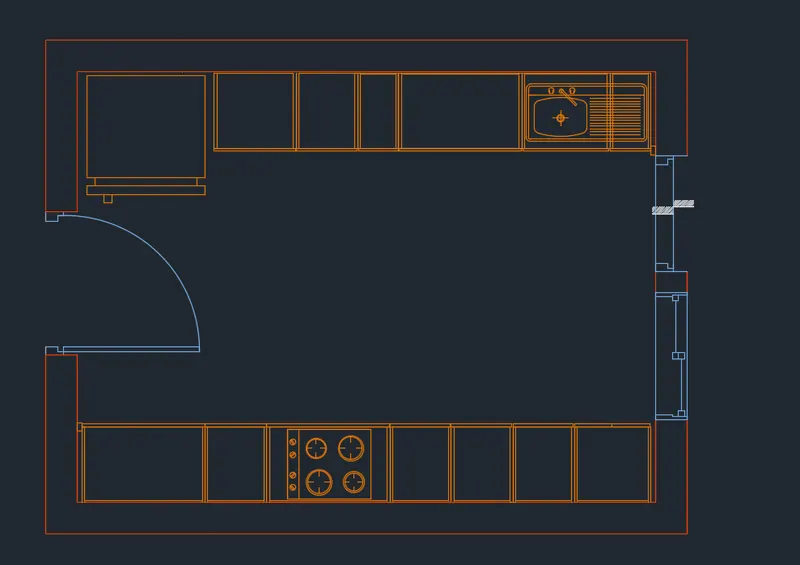
- Enter ADC in the command prompt. From the Palettes panel click on the DesignCentre icon.
- Fron the DESIGNCENTER dialog box select the required fixtures and appliances and copy them to the drawing sheet.
- Specify the base point, the Scale and position the fixtures and appliances according to the given drawing.
STEP 6
- Set current the Hatch layer.
- Specify the base point, the Scale and position the fixtures and appliances according to the given drawing.
- Select the Hatch tool, by entering H command, select ANSI32 pattern, and set the hatch scale as per requirement, pick the point.
- Press Esc.
- Select the Hatch tool, by entering H command, select Solid pattern, and set the hatch scale as per requirement, pick the point.
- Press Esc.
- Set current the Dimension and Text layer.
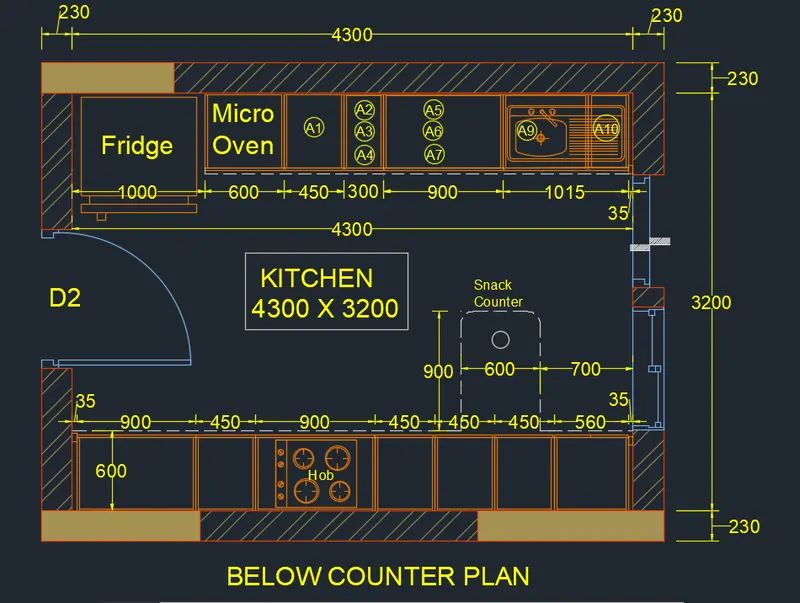
- Enter ‘DST’ command in the command tab to open the Dimension Style Manager dialog box.
- Click on the Modify tab.
- Under the Lines option change the colour of the dimension and extension lines.
- Under the Symbols and Arrows option change the Arrow size to 50.
- Under the Text option change the Text height to 100.
- Click OK. Then click on Set Current and Close the dialog box.
- Select the Dimension tool by entering 'DIM' in the command line.
- Select the first point and second point of the object to be measured, then drag the dimension line to the desired location. Repeat for all the objects to be measured.
- Enter 'MTEXT' command in the command line.
- Specify the start point of text as required.
- Scale the text to the desired size.
- Copy the text box to wherever necessary.
- Enter ED in the command promt and edit the text boxes as required.
- Click Enter and press Esc.
STEP 7
- Set current the Walls layer.
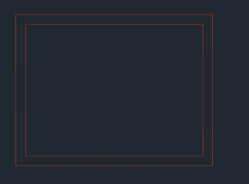
- Select the Rectangle tool by entering ‘REC’ command in the command tab.
- Specify the first point.
- Select Dimensions option in the command line.
- Specify length of rectangle as 4760 in the command line.
- Specify width of rectangle as 3660 in the command line.
- Move the cursor towards the upward and click ENTER.
- Select the Offset tool by entering ‘OFFSET’ command in the command tab.
- As thickness of external wall is 230, enter 230 as offset distance in the command line.
- Select both the rectangle created before.
- Click on the inside to offset.
- Press Esc.
STEP 8
- Set current the doors and windows layer.
- Select the Line tool by entering ‘LINE’ command in the command tab.
- Create openings for the door and window.
- Press Esc.
- Select the Trim tool by entering ‘TR’ command in the command tab.
- Press ENTER.
- Select Edge option; and click on No Extend.
- Select the extruted lines.
- Press ‘Esc’ to cancel the TRIM command.
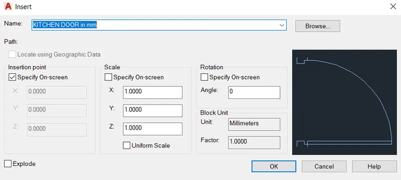
- Enter 'i' command in the command line.
- In the Insert dialogbox, select the Kitchen door in mm block.
- Click OK.
- Repeat i command for inserting the windows.
STEP 9
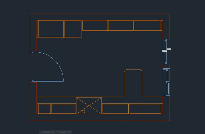
- Set current the furniture and fitting layer.
- Select the Line tool by entering ‘LINE’ command in the command tab.
- Specify the start point.
- Draw a horizontal line of length 35 from the bottom left inner edge of the kitchen wall.
- Press Esc.
- Select the Rectangle tool by entering ‘REC’ command in the command tab.
- Specify the first point at the inner edge of the .
- Select Dimensions option in the command line.
- Specify length of rectangle as 450 in the command line.
- Specify width of rectangle as 350 in the command line.
- Move the cursor towards the upward and click ENTER.
- Select the rectangle and click on the Explode icon in the Ribbon.
- Select the Offset tool by entering ‘OFFSET’ command in the command tab.
- Specify offset distance as 20.
- Offset the top, right and left sides of the rectangle.
- Repeat offset, specify offset distance as 10.
- Offset the bottom edge of the rectangle
- Press Esc.
- Select the Rectangle tool by entering ‘REC’ command in the command tab.
- Specify the first point at the inner edge of the .
- Select Dimensions option in the command line.
- Specify length of rectangle as 900 in the command line.
- Specify width of rectangle as 350 in the command line.
- Move the cursor towards the upward and click ENTER.
- Select the rectangle and click on the Explode icon in the Ribbon.
- Select the Offset tool by entering ‘OFFSET’ command in the command tab.
- Specify offset distance as 20.
- Offset the top, right and left sides of the rectangle.
- Repeat offset, specify offset distance as 10.
- Offset the bottom edge of the rectangle
- Press Esc.
- Leave a gap of 900 mm for the chimney.
- Select the Rectangle tool by entering ‘REC’ command in the command tab.
- Specify the first point at the inner edge of the .
- Select Dimensions option in the command line.
- Specify length of rectangle as 900 in the command line.
- Specify width of rectangle as 350 in the command line.
- Move the cursor towards the upward and click ENTER.
- Select the rectangle and click on the Explode icon in the Ribbon.
- Select the Offset tool by entering ‘OFFSET’ command in the command tab.
- Specify offset distance as 20.
- Offset the top, right and left sides of the rectangle.
- Repeat offset, specify offset distance as 10.
- Offset the bottom edge of the rectangle
- Press Esc.
- Select the Rectangle tool by entering ‘REC’ command in the command tab.
- Specify the first point at the inner edge of the .
- Select Dimensions option in the command line.
- Specify length of rectangle as 1010 in the command line.
- Specify width of rectangle as 350 in the command line.
- Move the cursor towards the upward and click ENTER.
- Select the rectangle and click on the Explode icon in the Ribbon.
- Select the Offset tool by entering ‘OFFSET’ command in the command tab.
- Specify offset distance as 20.
- Offset the top, right and left sides of the rectangle.
- Press Esc.
- To draw the chimney, select the Rectangle tool by entering ‘REC’ command in the command tab.
- Specify the first point at the inner edge of the .
- Select Dimensions option in the command line.
- Specify length of rectangle as 850 in the command line.
- Specify width of rectangle as 550 in the command line.
- Move the cursor towards the upward and click ENTER.
- Select the Line tool by entering ‘LINE’ command in the command tab.
- Draw diagonal lines connecting the opposite corners of the rectangle drawn before.
- Press Esc.
- Select the Circle tool by entering ‘CIRCLE’ command in the command tab.
- Draw a circle at the bottom left corner of the rectangle.
- Press Esc.
- Select the Line tool by entering ‘LINE’ command in the command tab.
- Specify the start point.
- Draw a line joining the top inner edges of the kitchen wall, press Esc.
- Select the line, right click, go to properties and change the line type to ISO dash.
- Select the Rectangle tool by entering ‘REC’ command in the command tab.
- Specify the first point at the top right inner edge of the .
- Select Dimensions option in the command line.
- Specify length of rectangle as 35 in the command line.
- Specify width of rectangle as 50 in the command line.
- Move the cursor towards the upward and click ENTER.
- Select the Rectangle tool by entering ‘REC’ command in the command tab.
- Specify the first point at the inner edge of the .
- Select Dimensions option in the command line.
- Specify length of rectangle as 860 in the command line.
- Specify width of rectangle as 350 in the command line.
- Move the cursor towards the upward and click ENTER.
- Select the rectangle and click on the Explode icon in the Ribbon.
- Select the Offset tool by entering ‘OFFSET’ command in the command tab.
- Specify offset distance as 20.
- Offset the bottom, right and left sides of the rectangle.
- Repeat offset command, specify offset distance as 10.
- Offset the top edge of the rectangle
- Press Esc.
- Select the Rectangle tool by entering ‘REC’ command in the command tab.
- Specify the first point at the inner edge of the .
- Select Dimensions option in the command line.
- Specify length of rectangle as 860 in the command line.
- Specify width of rectangle as 350 in the command line.
- Move the cursor towards the upward and click ENTER.
- Select the rectangle and click on the Explode icon in the Ribbon.
- Select the Offset tool by entering ‘OFFSET’ command in the command tab.
- Specify offset distance as 20.
- Offset the bottom, right and left sides of the rectangle.
- Repeat offset, specify offset distance as 10.
- Offset the top edge of the rectangle
- Press Esc.
- Select the Rectangle tool by entering ‘REC’ command in the command tab.
- Specify the first point at the inner edge of the .
- Select Dimensions option in the command line.
- Specify length of rectangle as 860 in the command line.
- Specify width of rectangle as 350 in the command line.
- Move the cursor towards the upward and click ENTER.
- Select the rectangle and click on the Explode icon in the Ribbon.
- Select the Offset tool by entering ‘OFFSET’ command in the command tab.
- Specify offset distance as 20.
- Offset the bottom, right and left sides of the rectangle.
- Repeat offset, specify offset distance as 10.
- Offset the top edge of the rectangle
- Press Esc.
- Select the Rectangle tool by entering ‘REC’ command in the command tab.
- Specify the first point at the inner edge of the .
- Select Dimensions option in the command line.
- Specify length of rectangle as 600 in the command line.
- Specify width of rectangle as 600 in the command line.
- Move the cursor towards the upward and click ENTER.
- Select the rectangle and click on the Explode icon in the Ribbon.
- Select the Offset tool by entering ‘OFFSET’ command in the command tab.
- Specify offset distance as 20.
- Offset the top, right and left sides of the rectangle.
- Repeat offset, specify offset distance as 10.
- Offset the bottom edge of the rectangle
- Press Esc.
- Select the Rectangle tool by entering ‘REC’ command in the command tab.
- Specify the first point at the inner edge of the .
- Select Dimensions option in the command line.
- Specify length of rectangle as 965 in the command line.
- Specify width of rectangle as 600 in the command line.
- Move the cursor towards the upward and click ENTER.
- Select the rectangle and click on the Explode icon in the Ribbon.
- Select the Offset tool by entering ‘OFFSET’ command in the command tab.
- Specify offset distance as 20.
- Offset the bottom, right and left sides of the rectangle.
- Repeat offset, specify offset distance as 10.
- Offset the top edge of the rectangle
- Press Esc.
- Select the Rectangle tool by entering ‘REC’ command in the command tab.
- Specify the first point at the inner edge of the .
- Select Dimensions option in the command line.
- Specify length of rectangle as 35 in the command line.
- Specify width of rectangle as 50 in the command line.
- Move the cursor towards the upward and click ENTER.
- Select the rectangle and click on the Explode icon in the Ribbon.
- Select the Offset tool by entering ‘OFFSET’ command in the command tab.
- Specify offset distance as 20.
- Offset the bottom, right and left sides of the rectangle.
- Repeat offset, specify offset distance as 10.
- Offset the top edge of the rectangle
- Press Esc.
- Select the Trim tool by entering ‘TR’ command in the command tab.
- Press ENTER.
- Select Edge option; and click on No Extend.
- Trim the unwanted portion of lines.
- Press ‘Esc’ to cancel the TRIM command.
STEP 10
- Set current the Hatch layer.
- Specify the base point, the Scale and position the fixtures and appliances according to the given drawing.
- Select the Hatch tool, by entering H command, select ANSI32 pattern, and set the hatch scale as per requirement, pick the point.
- Press Esc.
- Select the Hatch tool, by entering H command, select Solid pattern, and set the hatch scale as per requirement, pick the point.
- Press Esc.
- Set current the Dimension and Text layer.
- Select the Dimension tool by entering 'DIM' in the command line.
- Select the first point and second point of the object to be measured, then drag the dimension line to the desired location. Repeat for all the objects to be measured.
- Enter 'MTEXT' command in the command line.
- Specify the start point of text as required.
- Scale the text to the desired size.
- Copy the text box to wherever necessary.
- Enter ED in the command promt and edit the text boxes as required.
- Click Enter and press Esc.
- Save the drawing.
RESULT:
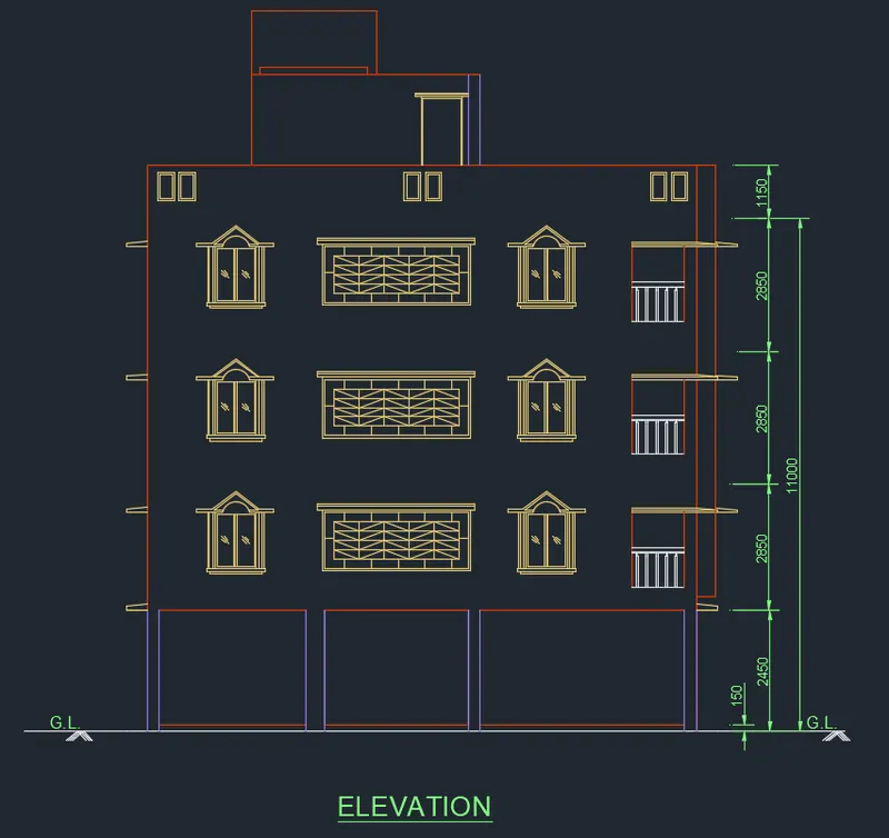
2) Creating the elevation of the plan created in the Challenges 7 and applying proper hatch in the walls, doors, windows, and other architectural elements:
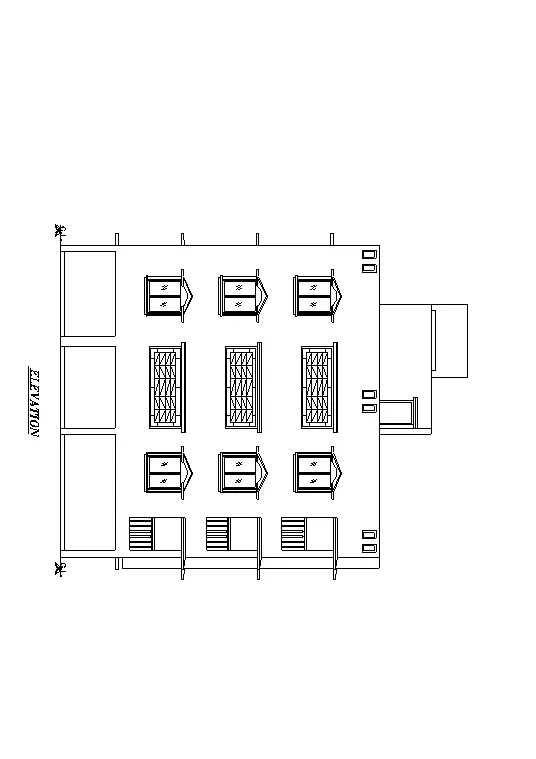
Aim:
- To draw the elevation of the plan created in the Challenges 7 and apply proper hatch in the walls, doors, windows, and other architectural elements as shown in the figure above, in AutoCAD
Introduction:
- The Elevation is created in AutoCAD using primarily the Xline and Line tools and after sketching, the objects, dimensions and texts and hatches are provided. The procedure of drawing is explained in detail with diagrams of each step and the final result is given.
Procedure:
STEP 1
- Go to START MENU, select AutoCAD 2022.
- In the Command line type in: STARTUP [ENTER]
- Enter new value of startup: 1
- Go to Application Menu and select New
- In the Startup dialog box set Metric as the default settings.
- Enter 'UNITS' command in the command tab.
- In the Drawing Units dialog box, select 'Decimal' in Type; ' 0 ' in Precision; and 'Millimeters' in Insertion scale.
- Click on 'OK'.
- Set the limits by entering LIMITS in the Command tab. The lower-left corner is specified as 0,0; and the upper-right corner is specified as 100000,100000.
STEP 2
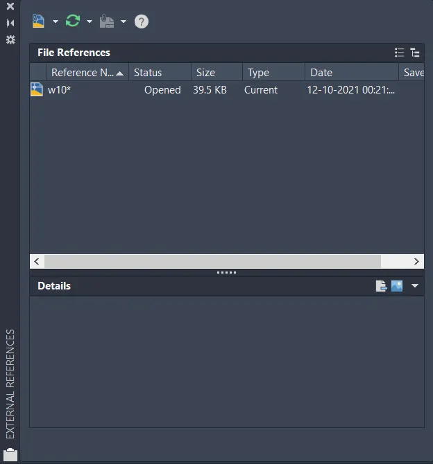
- Enter XREF in the command line.
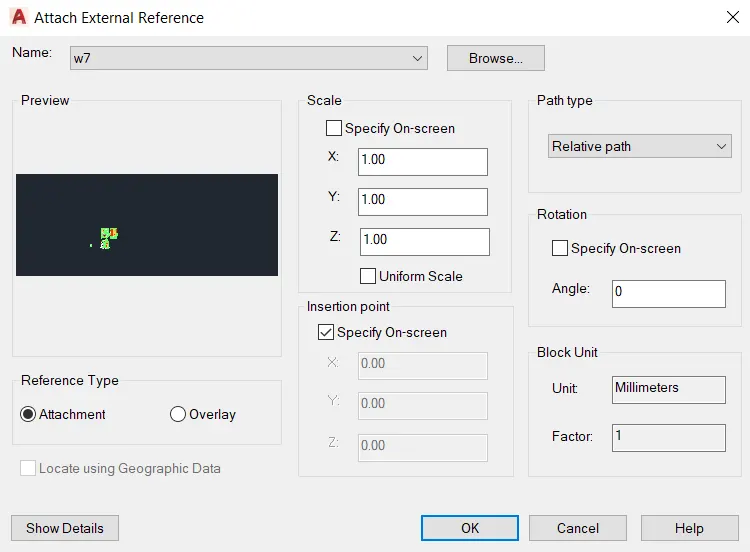
- Click on Attach DWG in the External reference Dialog box.
- Select the Week 7 drawing.
- Click OK.
- Again in the External reference Dialog box, right click on the attached file.
- Click on the Bind option and Select Insert.
STEP 3
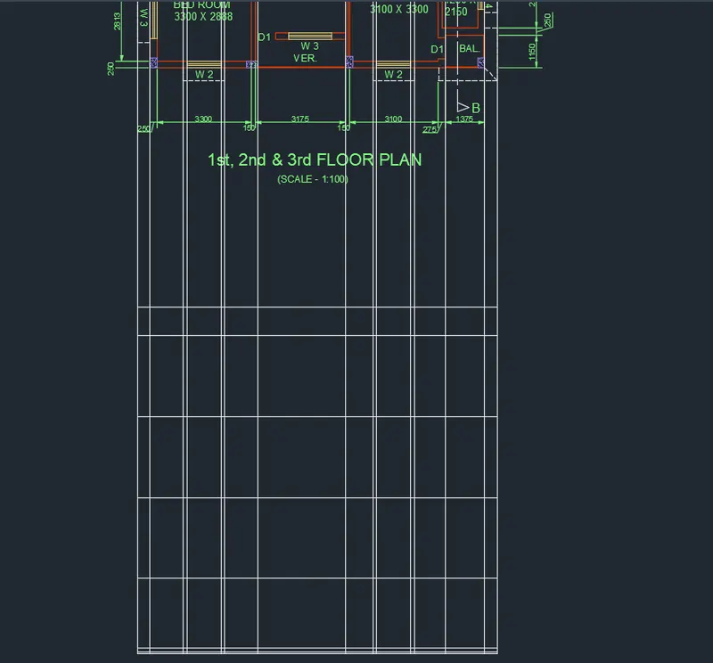
- Select the Construction Line tool by entering ‘XLINE’ command in the command tab.
- Enter V.
- Draw projection lines from the plan created.
- Agnain enter XL, press H.
- Draw a horizontal line at a suitable distance.
- Press Esc.
- Select the Trim tool by entering ‘TR’ command in the command tab.
- Press ENTER.
- Select Edge option; and click on No Extend.
- Select the extruted lines.
- Press ‘Esc’ to cancel the TRIM command.
- Select the Offset tool by entering ‘OFFSET’ command in the command tab.
- offset the horizontal line to distances of 2450 (ground floor height), 2850 (1st, 2nd, 3rd floors height), 1000 (parapet wall height)
- The horizontal Xlines are offsetted to distances as per the given room dimensions and wall thickness.
- Press ‘Esc’ to cancel the OFFSET command.
- Select the Trim tool by entering ‘TR’ command in the command tab.
- Press ENTER.
- Select Edge option; and click on No Extend.
- Select the extended lines.
- Press ‘Esc’ to cancel the TRIM command.
STEP 4
- Select the Trim tool by entering ‘TR’ command in the command tab.
- Press ENTER.
- Select Edge option; and click on No Extend.
- Select the unwanted lines.
- Press ‘Esc’ to cancel the TRIM command.
- Select the Offset tool by entering ‘OFFSET’ command in the command line.
- Create offsets according to the given drawing for the doors and windows, the height od door is taken as 2100, and the height of window is taken to be 600 for the smaller window and 1200 for the bigger window.
- Press Esc.
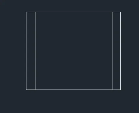
- For creating the windows, enter O in the command line.
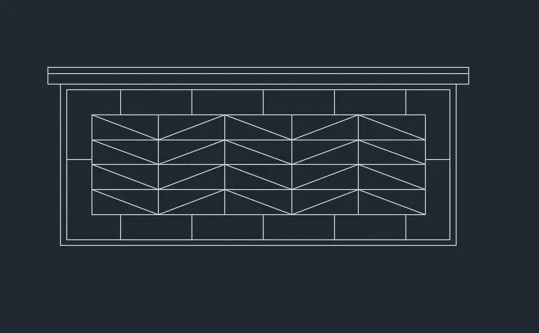
- Specify offset distannce of 50 and create the frame of the window by offsetting the lines on all four sides.
- Select the Line tool by entering ‘LINE’ command in the command tab.
- Specify the start point.
- Draw the top triangular portion of the window, press Esc.
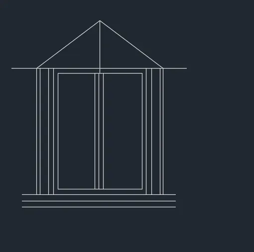
- Select the Arc tool from the ribbon, choose the Start, End, Direction option, then draw an arc at the top portion of the window.
- Press Esc.
- Select the Trim tool by entering ‘TR’ command in the command tab.
- Press ENTER.
- Select Edge option; and click on No Extend.
- Select the unwanted lines.
- Press Esc.
- Enter H in the command line.
- Select the GOST_GLASS pattern, pick point inside the window panel.
- Go to settings and in the Hatch and Gardient dialog box increase the scale of the hatch to a suitable value.
- Press Esc.

- For creating the verandah grill, enter O in the command line.
- Specify offset distannce of 50 and create the frame of the window by offsetting the lines on all four sides.
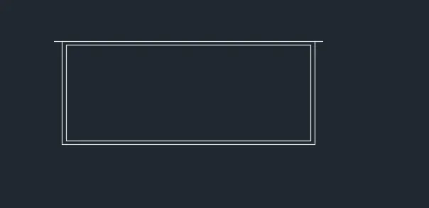
- Select the Offset tool by entering ‘OFFSET’ command in the command line.
- Specify offset distance of 150, select the four sides of the inner rectangle and click inside.
- Press Esc.
- Select the Divide tool from the Draw panel, select the left hand side line of the smaller rectancle and divide it into 4 sections.
- Select the Divide tool from the Draw panel, select the left hand side line of the smaller rectancle and divide it into 4 sections.
- Reselect the Divide tool from the Draw panel, select the top side line of the smaller rectancle and divide it into 4 sections.
- Select the Line tool by entering ‘LINE’ command in the command tab.
- Specify the start point.
- Draw lines through the divide points, press Esc.
- Delete the point markers.
- Select the Trim tool by entering ‘TR’ command in the command tab.
- Press ENTER.
- Select Edge option; and click on No Extend.
- Select the unwanted lines.
- Press Esc.
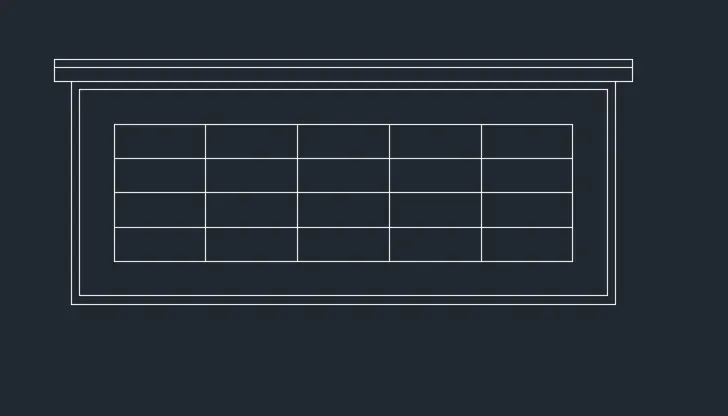
- Select the Line tool by entering ‘LINE’ command in the command tab.
- Draw diagonal lines to create the pattern as shown in the figure.
- Press Esc.
- Enter H in the command line.
- Select the AR_B816 pattern, pick point outside the smaller rectangle.
- Go to settings and in the Hatch and Gardient dialog box increase the scale of the hatch to a suitable value.
- Press Esc.
STEP 5
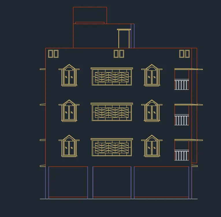
- Enter CO in the command line.
- Select the windows created.
- Specify the base point and copy the windows to the desired locations.
- Press Esc.
- Select the Trim tool by entering ‘TR’ command in the command tab.
- Select Edge option; and click on No Extend.
- Select the unwanted lines.
- Press ‘Esc’ to cancel the TRIM command.
- Assign the diferent objects to their respective layers.
- Select the Line tool by entering ‘LINE’ command in the command tab.
- Draw the balcony grills.
- Press Esc.
- Enter CO in the command line.
- Select the balcony created.
- Specify the base point and copy the balcony to the desired locations.
- Press Esc.
STEP 6
- Select the Dimension and Text layer.
- Select the Dimension tool by entering 'DIM' in the command line.
- Select the first point and second point of the object to be measured, then drag the dimension line to the desired location. Repeat for all the objects to be measured.
- Enter 'MTEXT' command in the command line.
- Specify the start point of text as required.
- Scale the text to the desired size.
- Copy the text box to wherever necessary.
- Enter ED in the command promt and edit the text boxes as required.
- Click Enter and press Esc.
- Save the drawing.
RESULT:
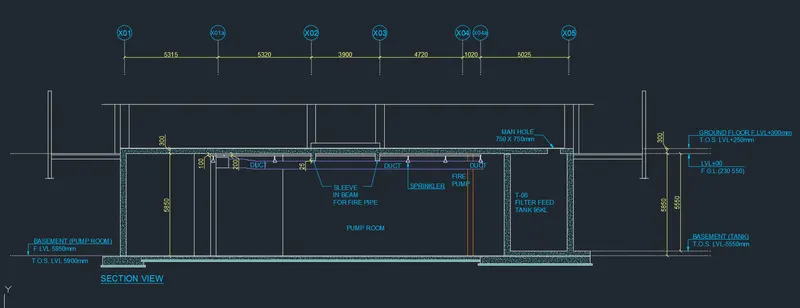
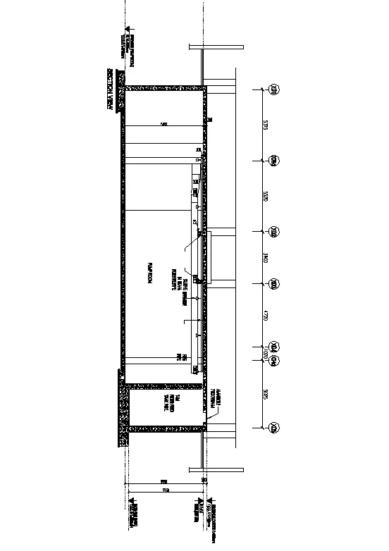
3) Creating the section view of an industrial building as shown in Figure. Providing appropriate hatches and dimensions wherever required. Also, providing annotations to the drawing:
Aim:
- To draw the section view of an industrial building as shown in the figure above, in AutoCAD.
Introduction:
- The section is created in AutoCAD using primarily the Rectangle, Line, Offset and Trim tools, the dimensions and text are provided with the use of layers. The procedure of drawing is explained in detail with diagrams of each step and the final result is given.
Procedure:
STEP 1
- Go to START MENU, select AutoCAD 2022.
- Go to Application Menu and select New
- In the Startup dialog box set Metric as the default settings.
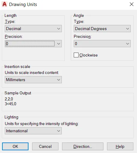
- Enter 'UNITS' command in the command tab.
- In the Drawing Units dialog box, select 'Decimal' in Type; ' 0 ' in Precision; and 'Millimeters' in Insertion scale.
- Click on 'OK'.
- Set the limits by entering LIMITS in the Command tab. The lower-left corner is specified as 0,0; and the upper-right corner is specified as 30000,30000.
- Enter 'UNITS' command in the command tab.
STEP 2
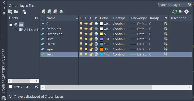
- Click on 'Layer Properties' in the Layer panel on the Ribbon.
- Click on 'New Layer' to create the following layers - Duct; Pipe; Hatch; Dimension and Text.
- Specify different colors for the different layers and then close the Layer Properties Manager dialog box.
STEP 3
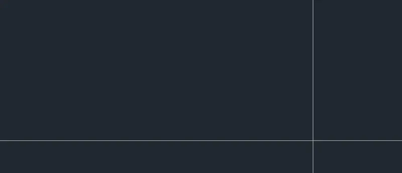
- Select the Construction Line tool by entering ‘XLINE’ command in the command tab.
- Enter V.
- Draw a vertocal line.
- Agnain enter XL, press H.
- Draw a horizontal line.
- Press Esc.
STEP 4
- Select the Trim tool by entering ‘TR’ command in the command tab.
- Press ENTER.
- Select Edge option; and click on No Extend.
- Select the extruted lines.
- Press ‘Esc’ to cancel the TRIM command.
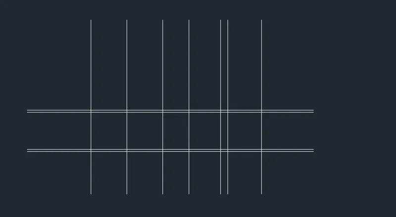
- Select the Offset tool by entering ‘OFFSET’ command in the command tab.
- Offset the vertical line to distances as shown in the given figure.
- The horizontal Xlines are offsetted to distances as per the given room dimensions and wall thickness.
- Press ‘Esc’ to cancel the OFFSET command.
- Select the Trim tool by entering ‘TR’ command in the command tab.
- Press ENTER.
- Select Edge option; and click on No Extend.
- Select the extended lines.
- Press ‘Esc’ to cancel the TRIM command.
STEP 5
- Select the Trim tool by entering ‘TR’ command in the command tab.
- Press ENTER.
- Select Edge option; and click on No Extend.
- Select the extruted lines.
- Press ‘Esc’ to cancel the TRIM command.
- Select the Line tool by entering ‘LINE’ command in the command tab.
- Draw lines to create the duct and pipes and other details inside the pump room.
- Press Esc to cancel the LINE command.
- Trim, Extend and Erase the lines as required.
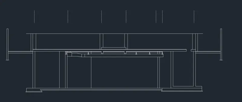
STEP 6
- Set current the Hatch layer.
- Select the Hatch tool, by entering H command, select AR-CONC pattern, and set the hatch scale as per requirement, pick the point.
- Press Esc.
- Enter HE in the command line, and edit the hatch as necessary.
- Close the Hatch Edit dialogue box.
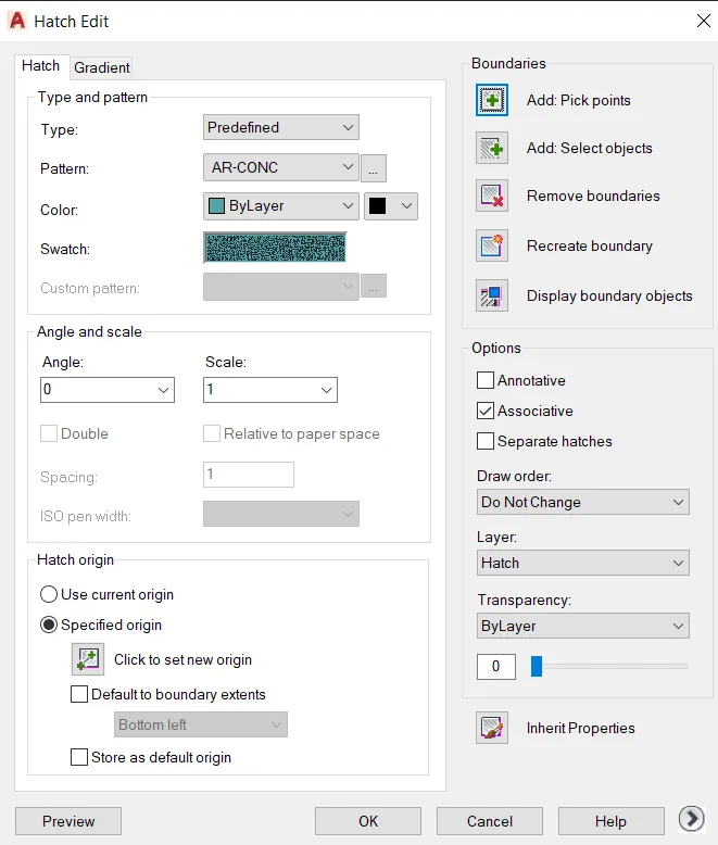
- Select the Hatch tool, by entering H command, select Solid pattern, and set the hatch scale as per requirement, pick the point as the base of the pump room section.
- Press Esc.
- Set current the Dimension layer.
- Enter ‘DST’ command in the command tab to open the Dimension Style Manager dialog box.
- Click on the Modify tab.
- Under the Lines option change the colour of the dimension and extension lines.
- Under the Symbols and Arrows option change the Arrow size to 200.
- Under the Text option change the Text height to 250.
- Click OK. Then click on Set Current and Close the dialog box.
- Select the Dimension tool by entering 'DIM' in the command line.
- Select the first point and second point of the object to be measured, then drag the dimension line to the desired location. Repeat for all the objects to be measured.
- Enter 'MTEXT' command in the command line.
- Specify the start point of text as required.
- Scale the text to the desired size.
- Copy the text box to wherever necessary.
- Enter ED in the command promt and edit the text boxes as required.
- Click Enter and press Esc.
- In Annotate panel, go to Multileader Style Manager, selct the standard option, click on Modify and make necessary changes, click OK and Set current.
- Select the Multileader tool and create multileaders wherever required as per the given drawing.
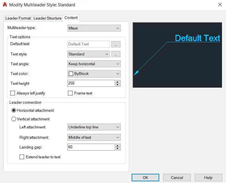
- Save the drawing.
RESULT: