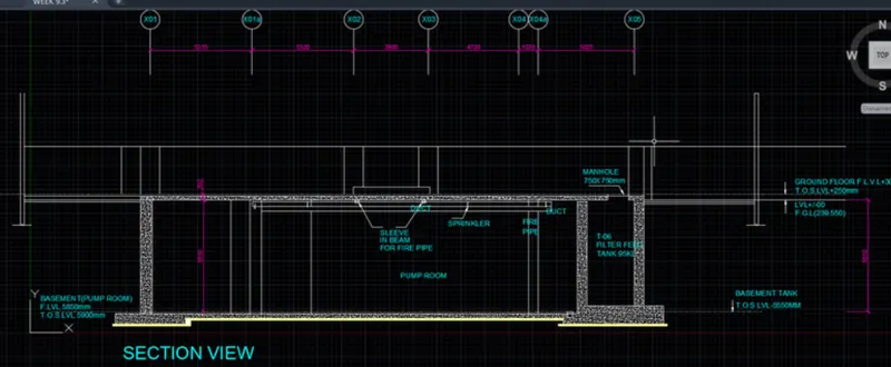
Creating Kitchen layout, Hatching of Architectural elements and sectional view of an Industrial Building in AutoCad
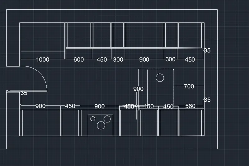
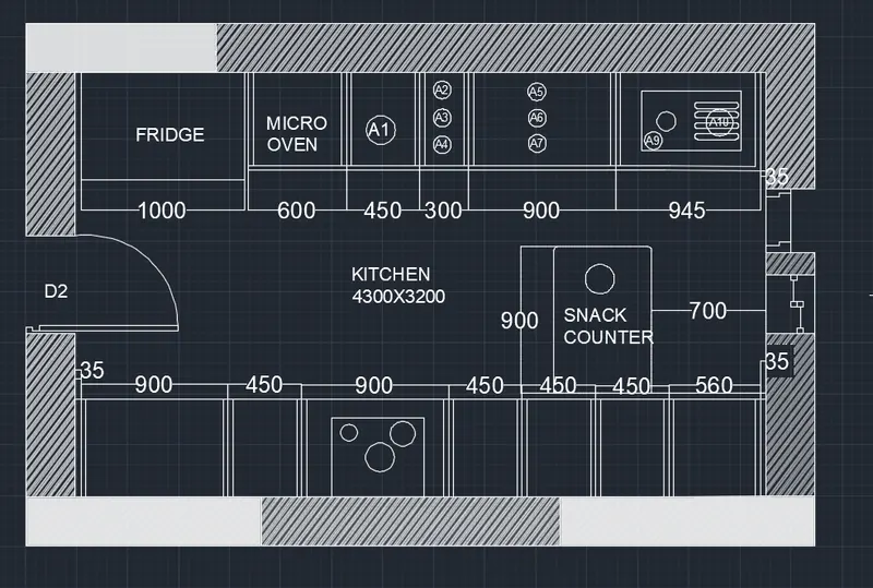
1.AIM:Create the layouts of the Kitchen and provide hatches pattern as shown. Also, use blocks wherever
required. Provide appropriate dimensions in the plan. Assume the size of doors, appliances and others
as per the standards.
STEP1:
PROCEDURE:
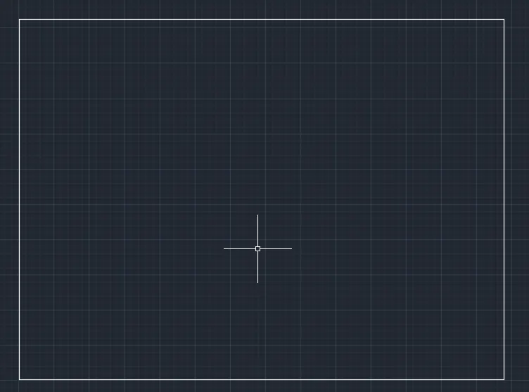
Draw the rectangle by using the rect cmt @ 4300x3200
STEP2:
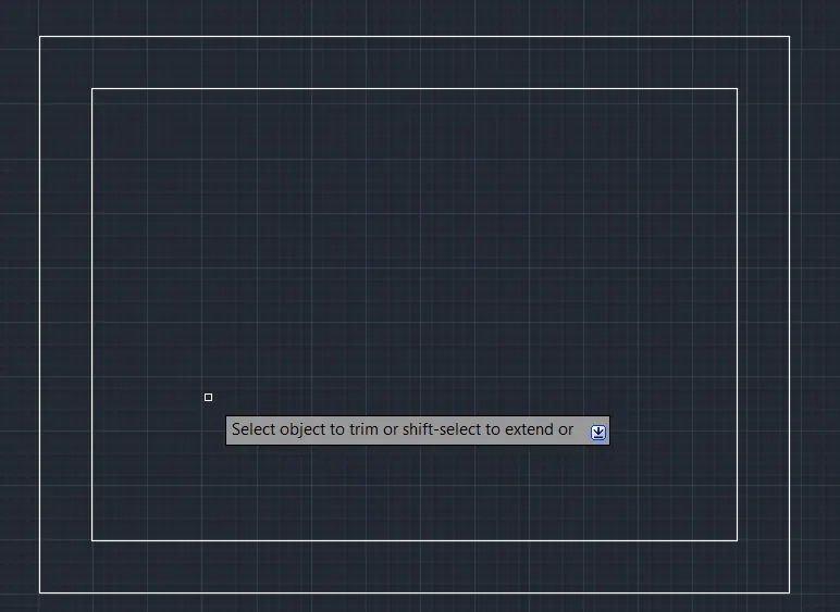
using the offset cmt draw the offset rectangle
STEP 3
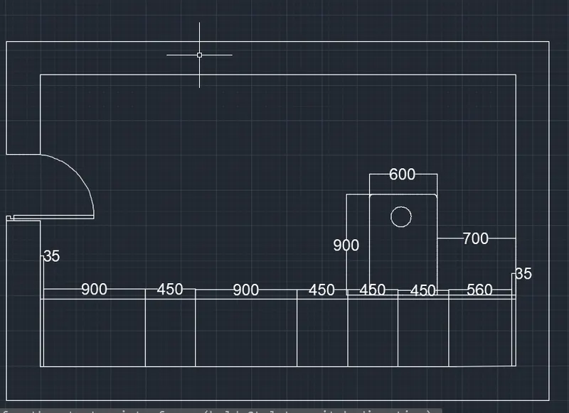
using of the line cmt draw the line dimension like given in the diagram
using of block insert the door
using of the dli cmt mark the measurement
using block line draw the block for the snack counter @ 600,900
type c enter draw the circle
STEP4:
using of the line cmt draw the line dimension like given in the diagram
using of the dli cmt mark the measurement
STEP5:
insert the text in the plan
using hatch cmt make the hatch for boundary walls
result:
B) PROCEDURE
THIS PLAN ALSO SAME LIKE THE PREVIOUS PLAN LITTLE DIFFERENT IN THIS SO I CAN DRAW DIRECTLY
PROCEDURE:
Draw the rectangle by using the rect cmt @ 4300x3200
using the offset cmt draw the offset rectangle
using of the line cmt draw the line dimension like given in the diagram
using of block insert the door
using of the dli cmt mark the measurement
using block line draw the block for the snack counter @ 600,900
type c enter draw the circle
using of the line cmt draw the line dimension like given in the diagram
using of the dli cmt mark the measurement
nsert the text in the plan
using hatch cmt make the hatch for boundary walls
result:
D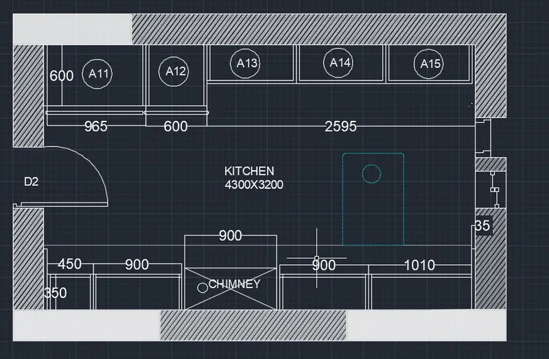
2.AIM:
STEP 1:
PROCEDURE:
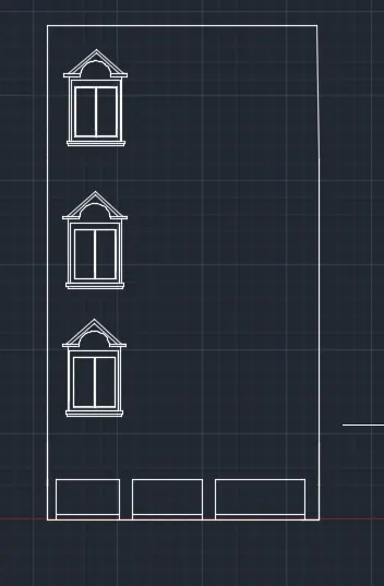
Draw the rectangle for elevation using rectangle cmt
step2:
draw the window and as like the plan
using of copy cmt insert the window
using of line draw the ground level
STEP3:
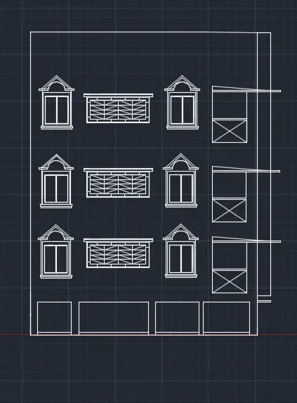
using line cmt draw the balcony as like in plan
inset the windows and balcony using copy cmt
 r
r
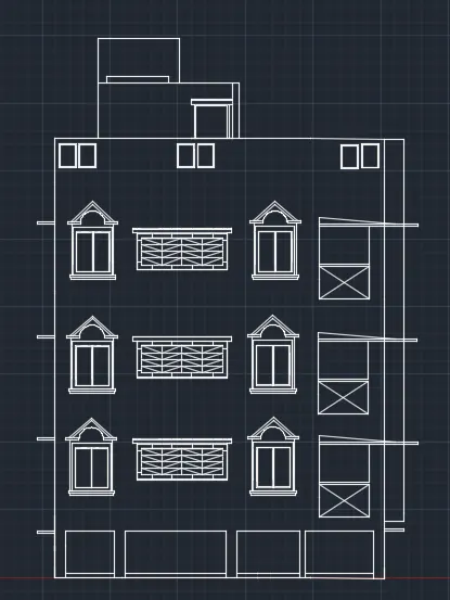
RESULT:
3.AIM:Create the section view of an industrial building as shown in Figure. Provide appropriate hatches and
dimensions wherever required. Also, provide annotations to the drawing.
STEP1 PROCEDURE
COMMAND IS USED ARE:
LINE CMT
XLINE CMT
OFFSET CMT
TRIM CMT
EXTEND CMT
DIMSTYLE CMT
DIMLINEAR CMT
LAYER CMT
HATCH CMT
GRADIENT CMT
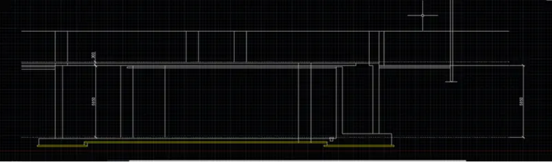
RESULT:
INSERT THE TEXT IN THE PLAN