Creating Conceptual mass in REVIT and Creation of Sinusoidal curve and a Parametric stadium using Dynamo
1) Using Dynamo create a set of sinusoidal points and create a curve and create a surface out of the curve.
AIM: To create a set of sinusoidal points and create a curve and create a surface out of the curve.
INTRODUCTION:
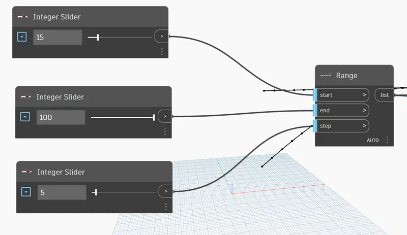
STEP-1: To open a dynamo and first to search a "Integer slider" to copy and paste 3 times as start, end & step,
then to search a "Range" and point the similar path from integer slider to range.
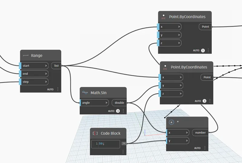
STEP-2: a. Search a Point.ByCoordinartes 2 times
b. and the first Point.ByCoordinartes linked by (Range list < first Point.ByCoordinartes in "x")
c. link an another (Range list < second Point.ByCoordinartes in "x")
d. then to search a Math.Sin and to link (Math.Sin double < second Point.ByCoordinartes in "y")
e. next step to search a "Product" in multiplication to link the ( Math.Sin < Product in "x")
f. and to link with ( Product number < first Point.ByCoordinartes in "z")
g. and to search "Code block" to enter "50;" to link (Code block" to enter "50;" < second Point.ByCoordinartes in "z"
h. to link (Code block" to enter "50;" < Product in "y")
STEP-3:
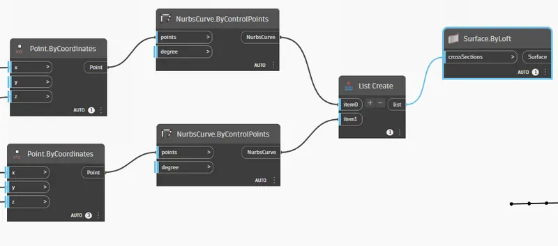
a. To search the NurbsCurve copy and paste once then to link the
(first Point.ByCoordinartes in point < first NurbsCurve.ByControlPoints in points)
b. and to link the (second Point.ByCoordinartes in point < second NurbsCurve.ByControlPoints in points)
c. To search a "List" and link a (first NurbsCurve.ByControlPoints in NurbsCurve to list create item0 )
d. then to link a (second NurbsCurve.ByControlPoints in NurbsCurve to list create item1 )
e. final stage to search a "Surface.ByLoft" to link (List Create in list < Surface.ByLoft in Surface)
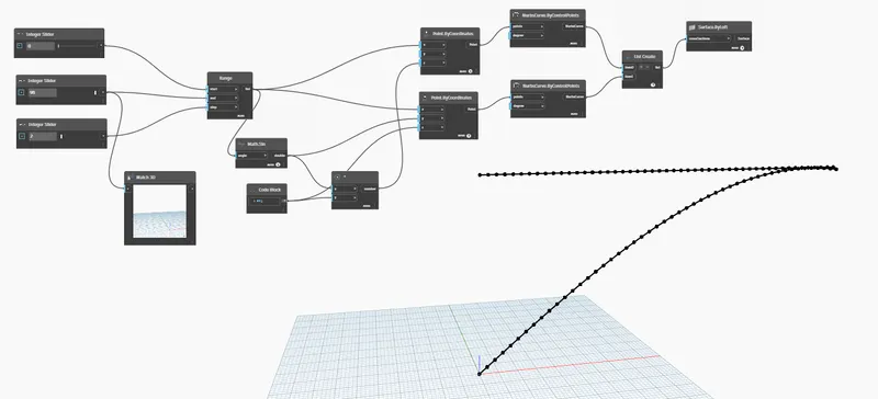
RESULT: Therefore, the sinusoidal points are created as a model to demonstrated in step by step construct.
2) Create a conceptual layout of floor plan in dynamo . Using the tools available in dynamo link the lines to appropriate model elements in Revit by choosing the wall types and wall parameters. Make use of the sliders to slide through the height of the wall and length of the wall.
AIM: To Create a conceptual layout of floor plan in dynamo . Using the tools available in dynamo link the lines to appropriate model elements in Revit by choosing the wall types and wall parameters. Make use of the sliders to slide through the height of the wall and length of the wall.
INTRODUCTION:
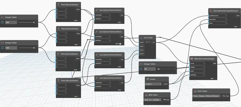
STEP-1: To open a dynamo and first to search a "Integer slider" to copy and paste Extra 1 time
then to search a "Point.ByCoordinartes" - 4 times and point the similar path from integer slider to Point.ByCoordinartes.
Then to search a Line.ByStartEndPoint - 4 times then to pick points from Start and Endpoint.
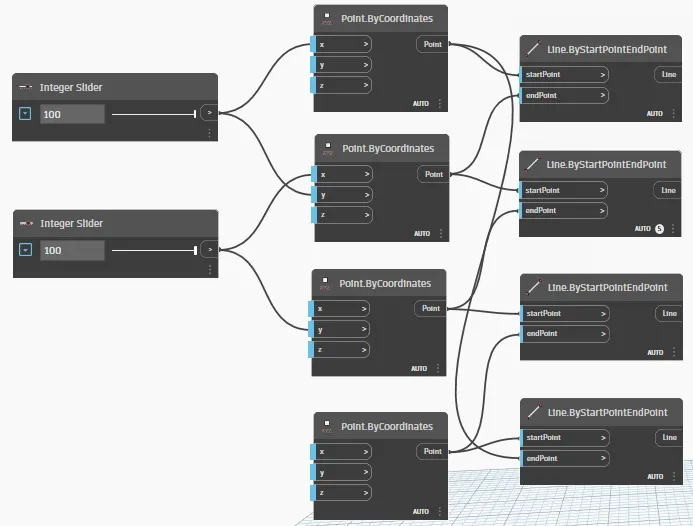
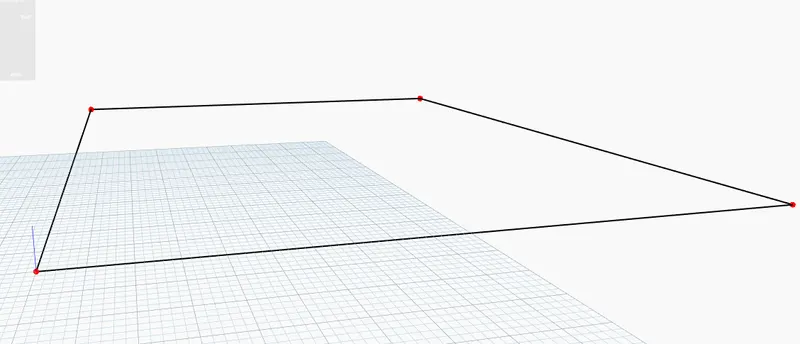
The wall coordintes has been created by using Dynamo
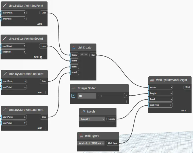
STEP-2: To search a "List Create", "1 Integer Slider", "Levels" & "Wall Types".
then to search a "Wall.ByCurveAndHeight" and link the path to common things.
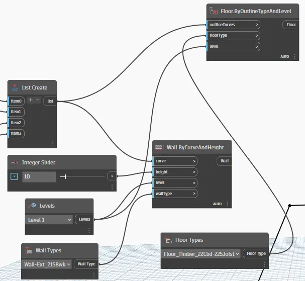
STEP-3: To search a "Floor.ByOutlineTypeAndLevel"
then to link with List Create, Levels & Floortypes.
RESULT: Therefore, the conceptual layout of floor plan in dynamo are created as a model to demonstrated in step by step construct.
3) Create an array of model elements in Revit. Use dynamo to vary the properties of model elements by using the slider or code block
AIM: To Create an array of model elements in Revit. Use dynamo to vary the properties of model elements by using the slider or code block.
INTRODUCTION:
STEP-1: To create a four Architecture columns from 90 degree angle.
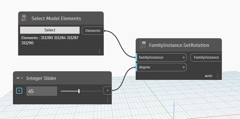
Then to open a dynamo and first to search a "Select Model Elements"

STEP-2: To search a Intereger Slider & FamilyInstance.SetRotatio.
Then to link the elements from family & integer
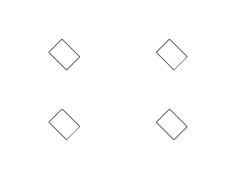
A column orientation as to be changed like this.
4) Create a conceptual mass in Revit and develop a parametric column by dividing the surfaces and apply the concepts similar to used in parametric walkway modelling. Use triangular bent or square shaped panels to add finish to the parametric column
AIM: To a conceptual mass in Revit and develop a parametric column by dividing the surfaces and apply the concepts similar to used in parametric walkway modelling. Use triangular bent or square shaped panels to add finish to the parametric column.
INTRODUCTION:
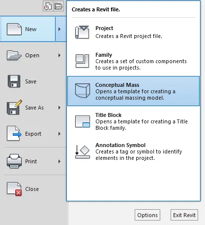
STEP-1: To open a new file < conceptual mass < Metric mass
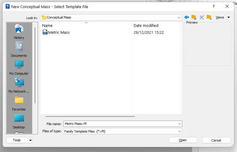
STEP-2: Create a line by using Spline Through Points from 12'-0" height
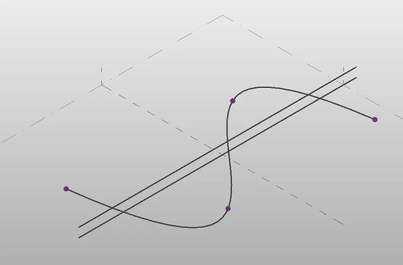
STEP-3: Create a Spline Through Point lines and to apply the set work plane from the nodes.
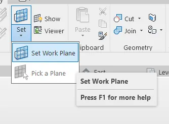
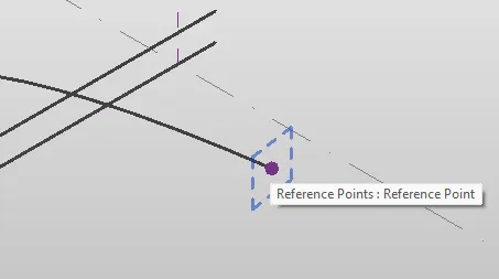
STEP-4: To create a petagonal shape from the work from planes and it has a height of 12'-0" to draw from every node plane points.
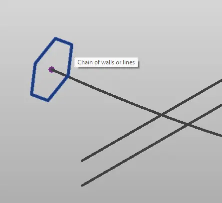
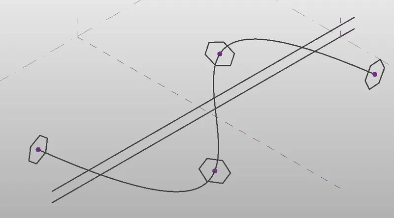
STEP-5: To select the Spline Through Point line and also simultaneously to select the end point of one petagonal
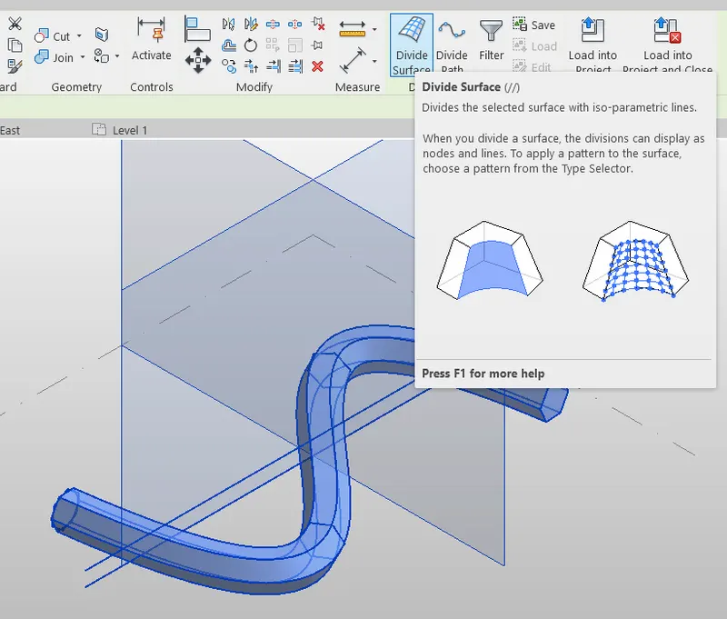
and to select the Create Form < Solid Form, then Spline Through Point line as to changed a "Solid Petagonal Curve"
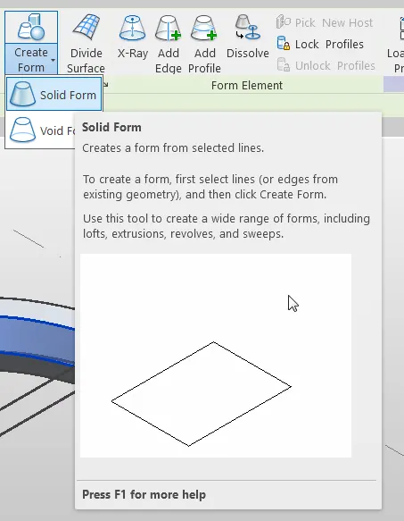
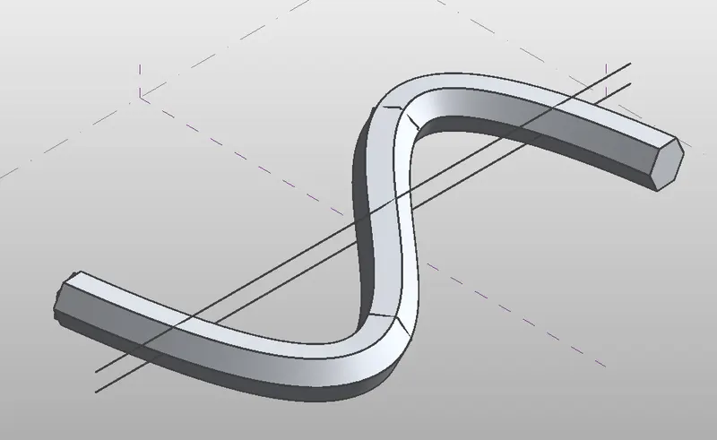
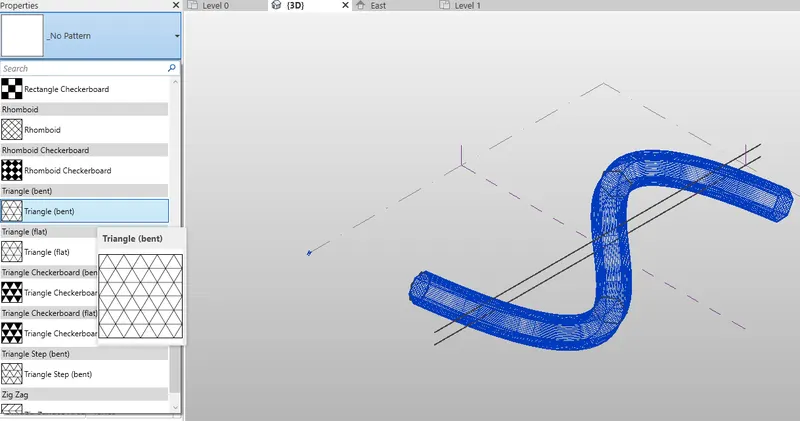
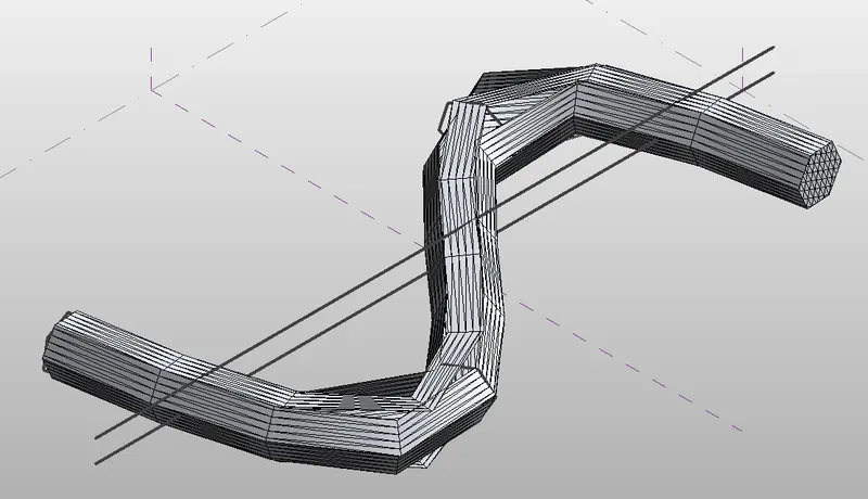
STEP-6: To select the all Solid Petagonal Curve and to select the "Divide Surface" to change the material of Solid Petagonal Curve
material has a "Triangular Bent"
5) Use Dynamo to work on developing a Parametric Stadium. List your parameters and use the visual programming approach to complete the modelling, You can use the concepts discussed in parametric high rise tower in class for reference.