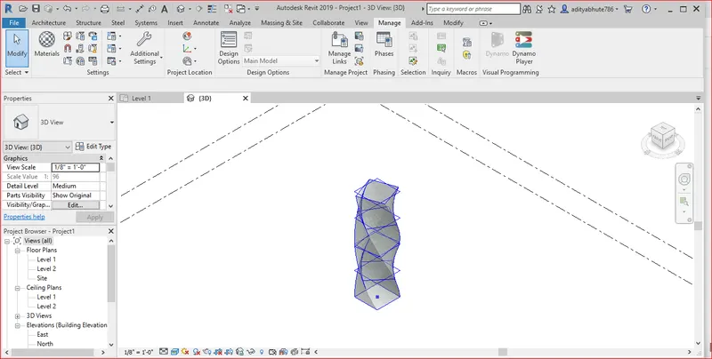
Creating Conceptual mass in REVIT and Creation of Sinusoidal curve and a Parametric stadium using Dynamo
CREATING CONCEPTUAL MASS IN REVIT AND CREATION OF SINUSOIDAL CURVE AND A PARAMETRIC STADIUM USING DYNAMO
AIM -
TO STUDY THE CREATION OF CONCEPTUAL MASS IN REVIT AND CREATION OF SINUSOIDAL CURVE AND A PARAMETRIC STADIUM USING DYNAMO
INTRODUCTION -
Autodesk Revit is a building information modeling software tool for architects, landscape architects, structural engineers, mechanical, electrical, and plumbing (MEP) engineers, designers, and contractors. The original software was developed by Charles River Software, founded in 1997, renamed Revit Technology Corporation in 2000, and acquired by Autodesk in 2002. The software allows users to design a building and structure and its components in 3D, annotate the model with 2D drafting elements, and access building information from the building model's database. Revit is 4D building information modeling capable with tools to plan and track various stages in the building's lifecycle, from concept to construction and later maintenance and/or demolition
Dynamo is an open-source visual programming language for Revit, written by designers and construction professionals. It is a programming language that allows you to type lines of code; while also creating an algorithm that consists of nodes. Using Dynamo, you can work with enhanced BIM capabilities in Revit. Dynamo and Revit together can be utilized to model and analyze complex geometries, automate repetitive processes, minimize human error, and export data to Excel files and other file types not typically supported by Revit. Dynamo can make the design process more efficient, with an intuitive interface and many pre-made scripting libraries available as well.
TASK 1) Using Dynamo creates a set of sinusoidal points and creates a curve and create a surface out of the curve.
PROCEDURE
STEP 1
- Go to the Window search box to open a Revit workspace.
- In the window search bar type REVIT, and the icon of the Revit application will show on the screen
- Click on the icon of REVIT, the application of Revit will open and the user interface of Revit will show on the screen.
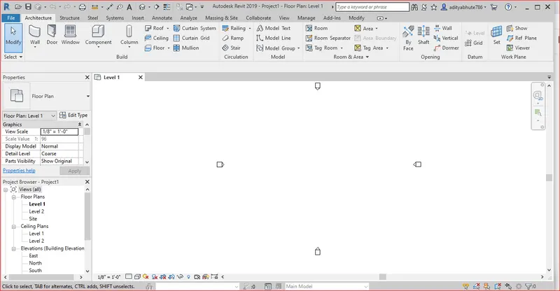
- Click on NEW and create a new architectural template.
STEP 2
- Open a Revit architectural template file.
- Now in the manage tab Click on the dynamo option.

STEP 3
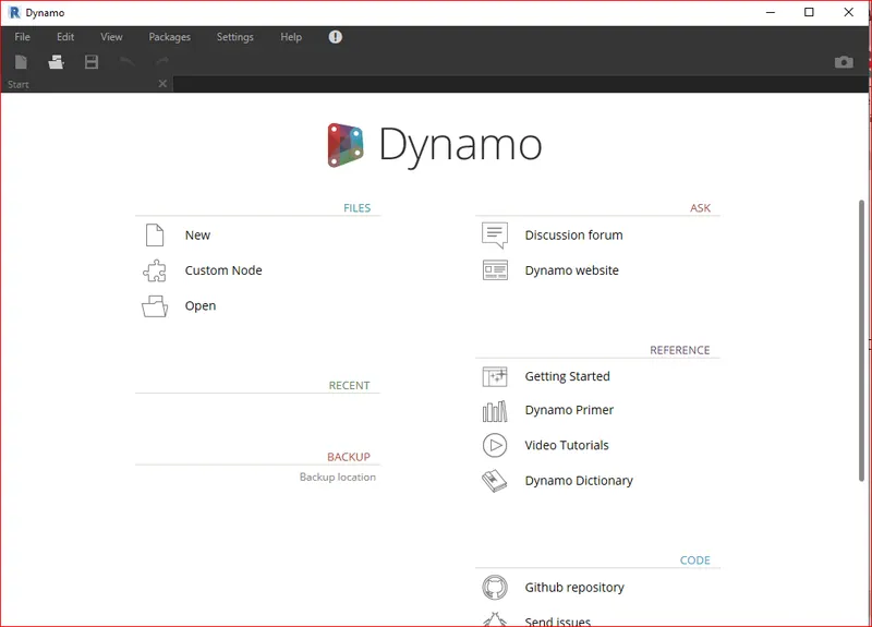
- The Dynamo window opens and clicks on the new to create a new file.
STEP 4
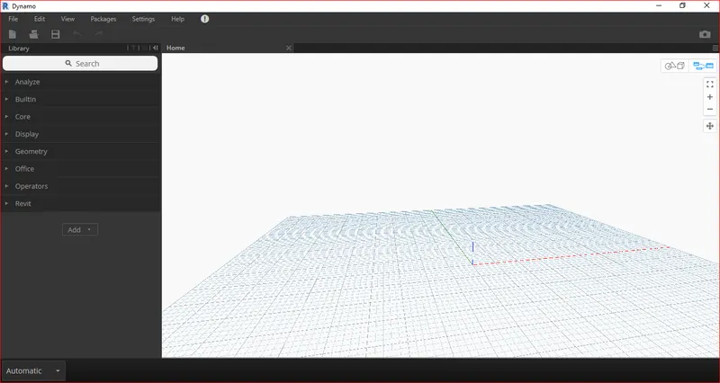
- A new Dynamo file is now opened as shown in the picture.
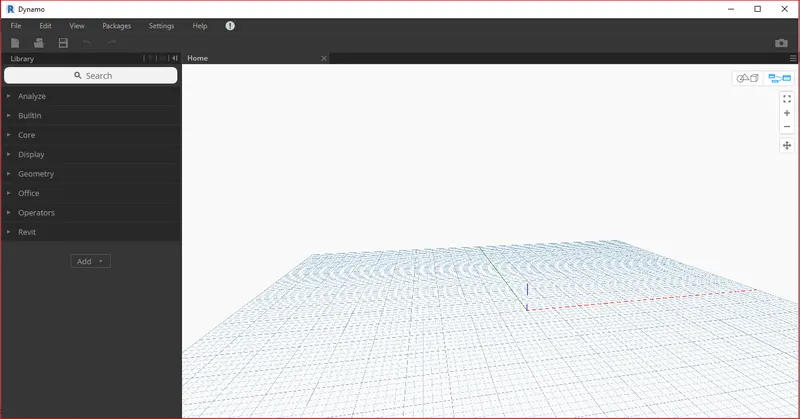
STEP 5
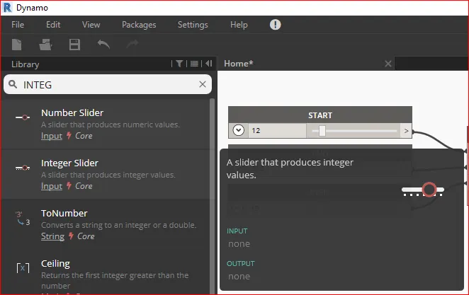
- To draw a curve certain parameters are required like start, end, and step, this can be done using the Integer slider.
- Search In library to the left search box as integer slider.
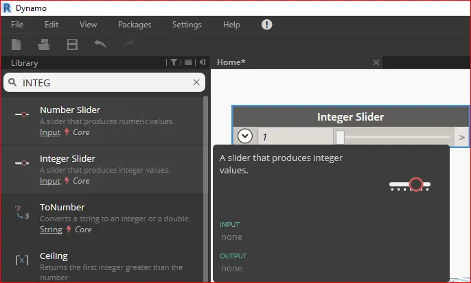
STEP 6
- Three integer sliders are inserted as shown in the picture.
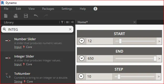
STEP 7
- Search for Range in the library panel box.
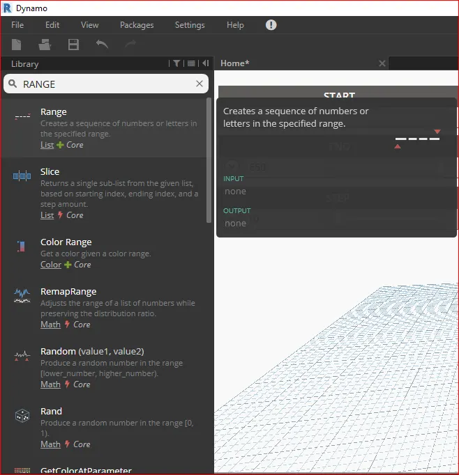
STEP 8
- And insert it into our workspace as shown on the screen.
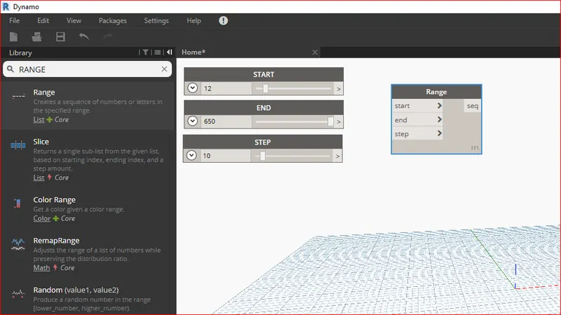
STEP 9
- Now connect the last parameter created as the start and end step to the range box.
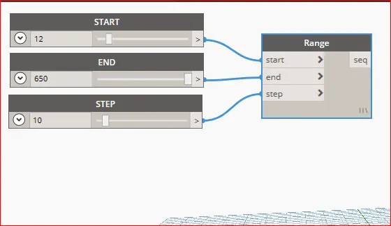
STEP 10
- Search a point by coordinates and select the first XYZ, coordinates.
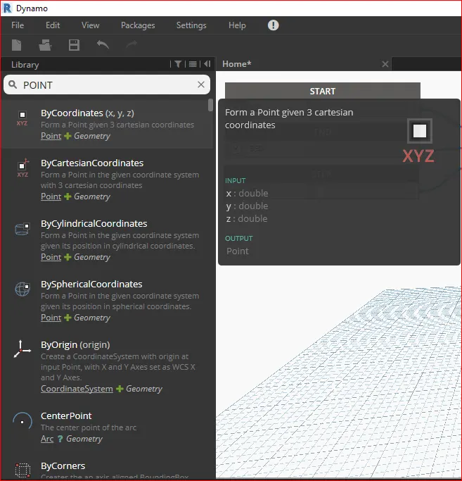
STEP 11
- And insert it in our workspace as shown on the screen.
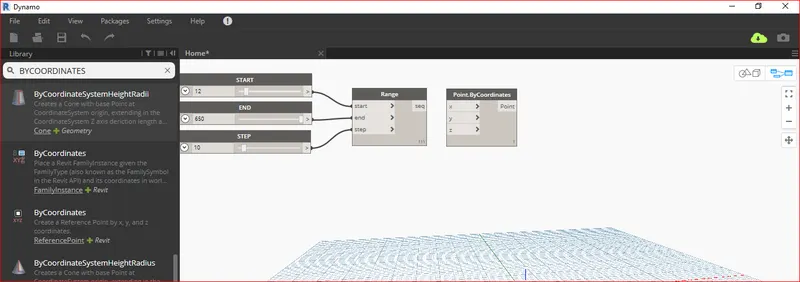
STEP 12
- Connect the range sequence to the x coordinates of the point by the coordinates box.
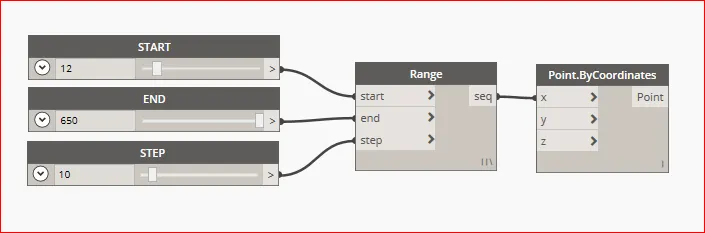
STEP 13
- the points are created as shown on the screen.
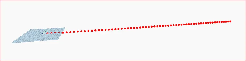
STEP 14
- To create a sin wave search MATH.SIN in the library panel.
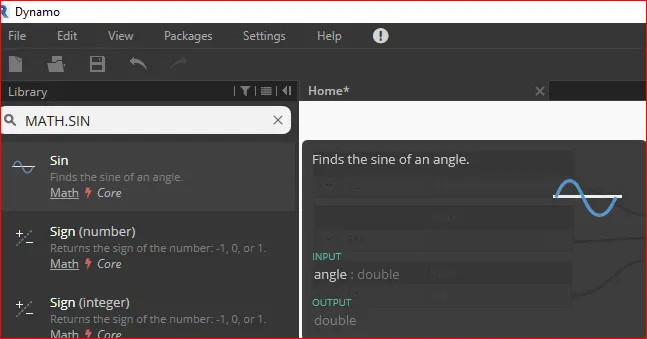
STEP 15
- Connect the range sequence to the ANGLE of the math. sin box.
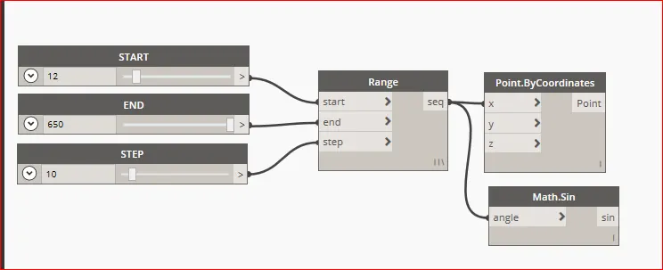
STEP 16
- Insert an integer slider for the amplifier and phase.
STEP 17
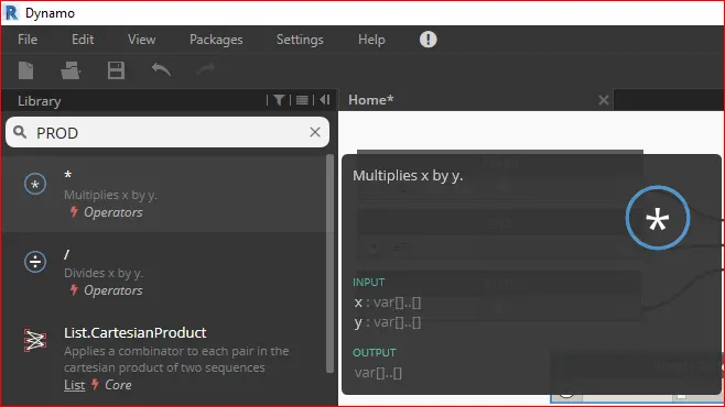
- Go to the library panel and type product to have a product box for the sin wave.
STEP 18
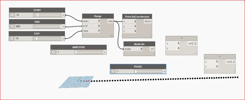
- Here, I insert two integer sliders and names as amplifier and phase and two product boxes.
STEP 19
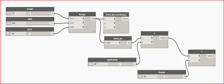
- Now connect the sin amplifier to x and y of product Respectively.
- And connect the product variable to the x of the second product box and specify the y value as Phase.
STEP 20
- Now connect the variable of the second product to the y of point by coordinate
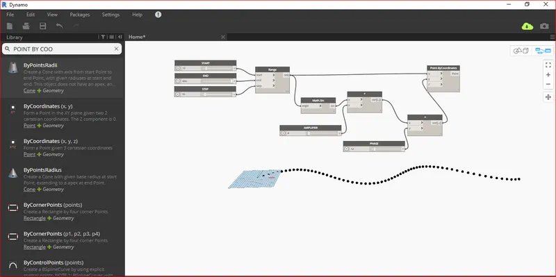
STEP 21
- Now a set of sinusoidal points is obtained as shown in the image.
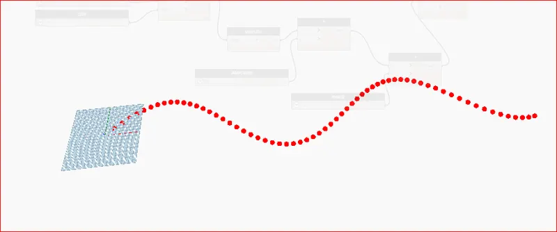
STEP 22
- The curve is created form nurbscurve
- Search for nurbscurve and select nurbs curve by control points
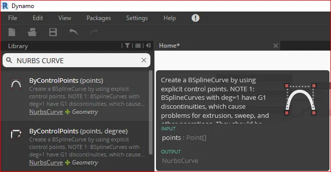
STEP 23
- Insert it and connect with the point of point by cooordinate box.
- the line is create through the point.
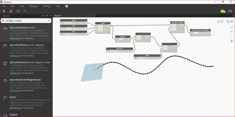
STEP 24
- Select the all the connection done pastly and make a group.
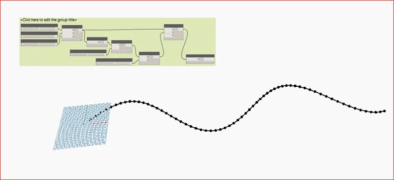
STEP 25
- Go to the edit tab and select the copy opion and select the group last created and make a 2 copy of it.
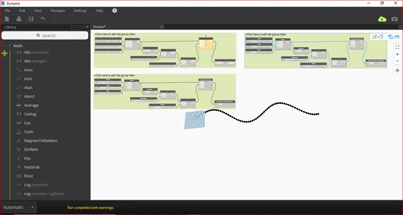
STEP 26
- Go to the edit tab and select the copy opion and select the group last created and make a 2 copy of it.
STEP 27
- Insert the list box and click on + and create 3 family
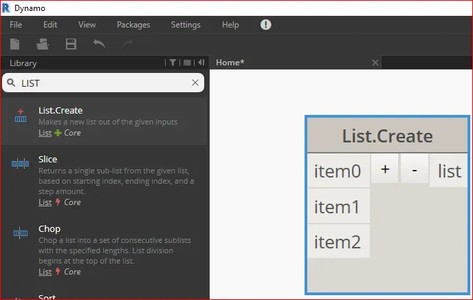
STEP 28
- Connect the nurbecurve to the list.
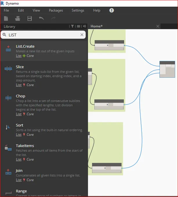
STEP 29
- To create a surface for the the curve insert the surface tab from the liabrary.
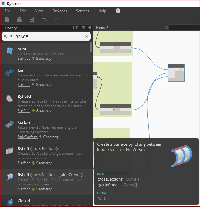
STEP 30
- Connect thee list with the cross Section of the surface
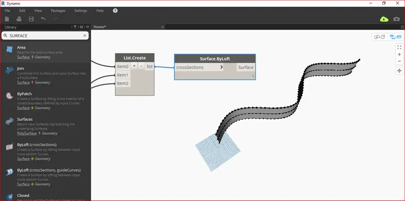
RESULT -
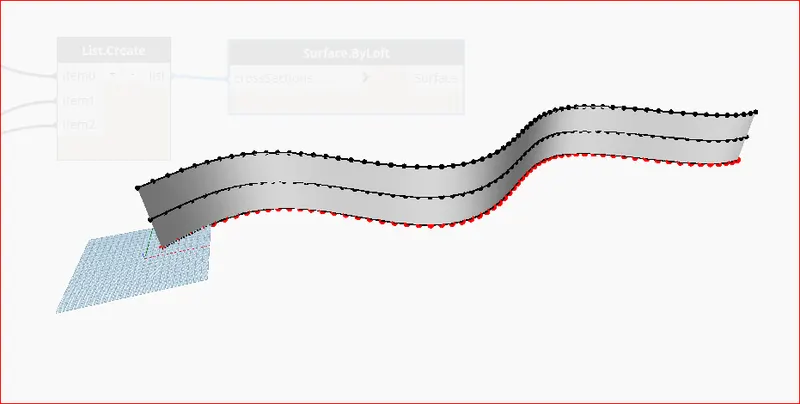
TASK 2) Create a conceptual layout of the floor plan in dynamo. Using the tools available in dynamo link the lines to appropriate model elements in Revit by choosing the wall types and wall parameters. Make use of the sliders to slide through the height of the wall and the length of the wall.
PROCEDURE
STEP 1-
- Go to the Window search box to open a Revit workspace.
- In the window search bar type REVIT, and the icon of the Revit application will show on the screen
- Click on the icon of REVIT, the application of Revit will open and the user interface of Revit will show on the screen.
- Click on NEW and create a new architectural template.
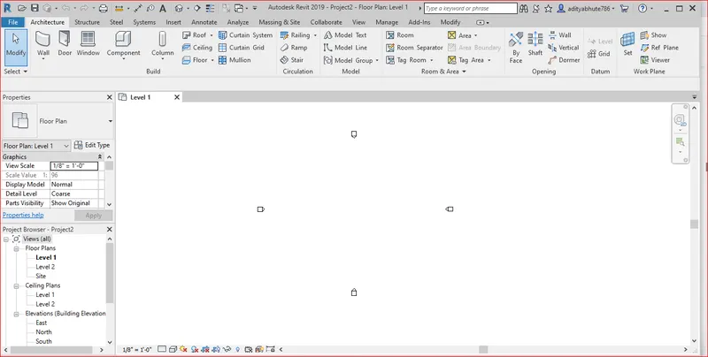
STEP 2
- Open a Revit architectural template file.
- Now in the manage tab Click on the dynamo option.

STEP 3
- The Dynamo window opens and clicks on the new to create a new file.
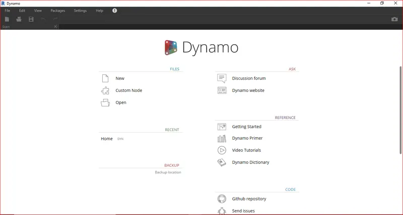
STEP 4
- A new Dynamo file is now opened as shown in the picture.

STEP 5
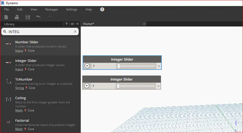
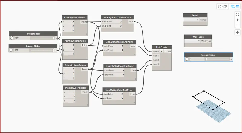
- Type the Interger in the library pannel and insert two integer slider in our project.
STEP 6
- Set the interger value as 100
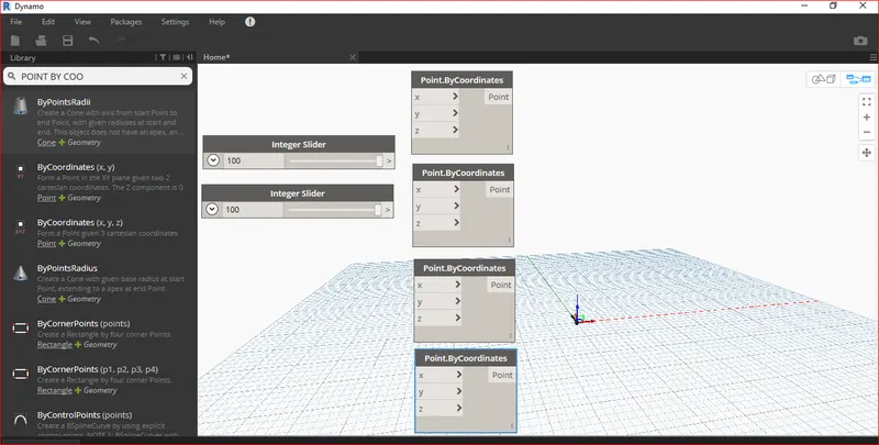
- Type the POINT BY COORIDINATE in the library pannel and insert four ponit boxex in our project.
STEP 7
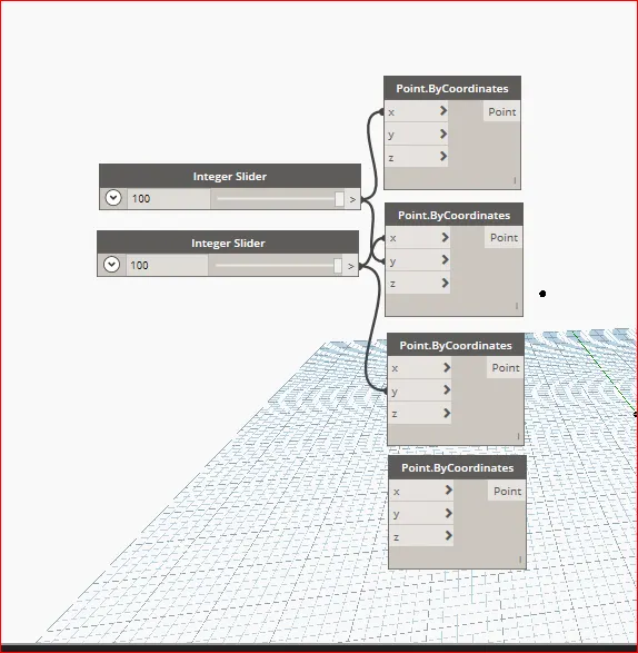
- Connect the integer slider to the points by cordinates as shown i the image.
STEP 8
- Type the LINE in the library pannel and insert four line bt start point end point in our project.
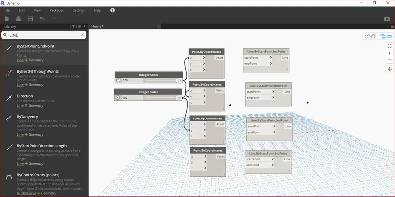
STEP 9
- Connect the points by cordinates to the line as shown i the image.
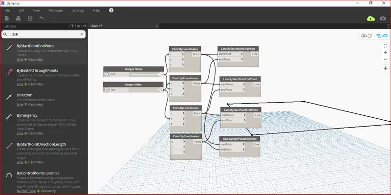
STEP 10
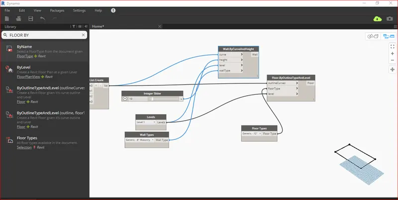
- Now a layout of a floor plan is created.
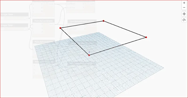
STEP 11
- Insert the list box and create a four families and connect with the lines.
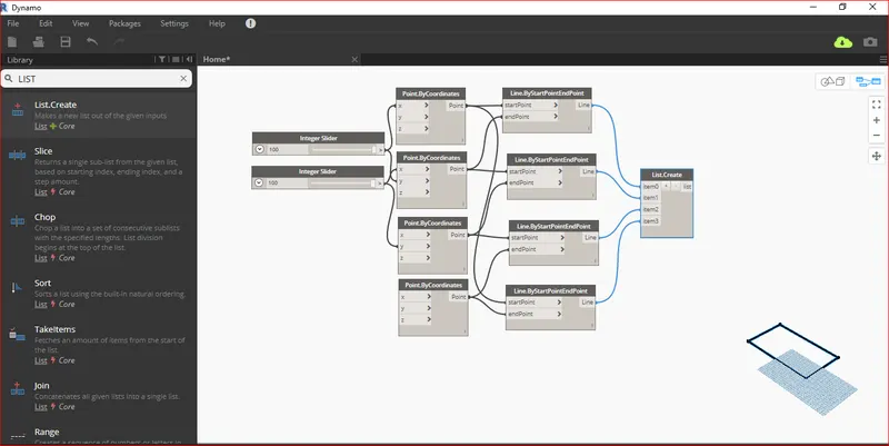
STEP 12
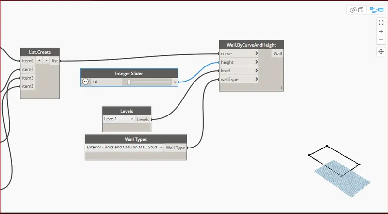
- Insert thee level, wall type, and one integer slider for height.
STEP 13
- Go to the library and type wall by curve and height and insert in the project
- Connect with the all the parameters created lastly.
STEP 14
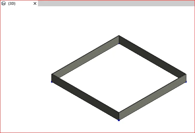
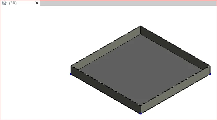
- Wall iis created as shown in the image.
STEP 15
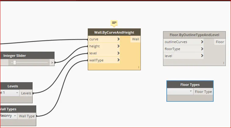
- To draw a floor insert two tab fom the library floor by outline type and level and floor type as shown.
STEP 16-
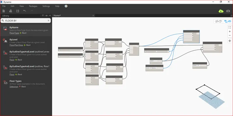
- Connect all the parameter to the floor by outline rtype and level box.
RESULT -
TASK 3) Create an array of model elements in Revit. Use dynamo to vary the properties of model elements by using the slider or code block
PROCEDURE
STEP 1
- Go to the Window search box to open a Revit workspace.
- In the window search bar type REVIT, and the icon of the Revit application will show on the screen
- Click on the icon of REVIT, the application of Revit will open and the user interface of Revit will show on the screen.
- Click on NEW and create a new architectural template.
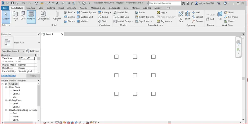
- Seleect the architecture column and place nine column in the workspace.
STEP 2
- Open the dynamo throught the mange tab of the Revit.
STEP 3
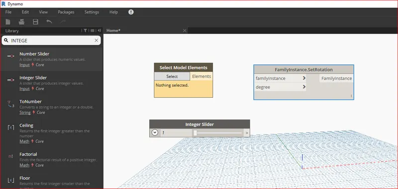
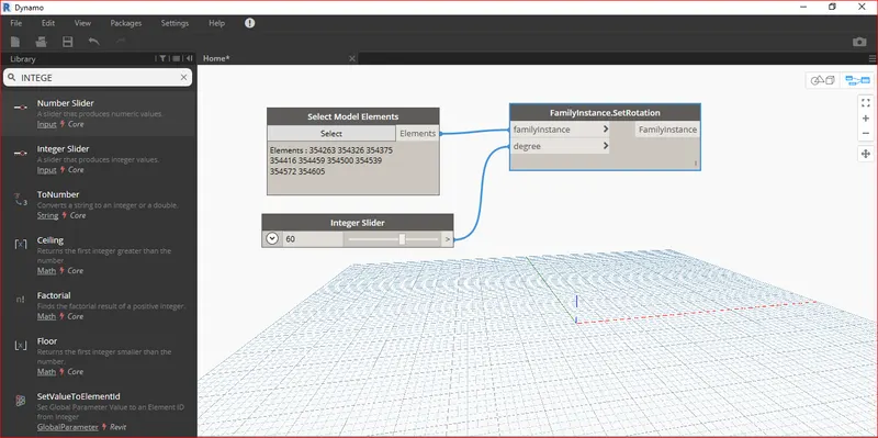
- Insert the select model element, integer slider and family instance rotation for the rotation of the column created in the Revit.
STEP 4
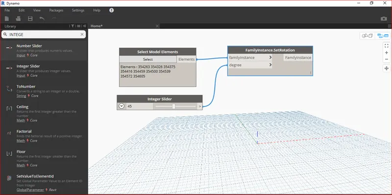
- Click on select and select all the columns and set the integer slider as 45
- Connect both the paraameters to the rotation.
STEP 5
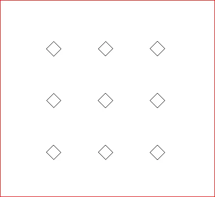
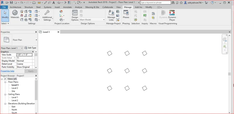
- Go to the revit workspace where all the column are rotated to the 45 degree.
STEP 6
- Go to the DYNAMO nad change the value of integer slider from 45 to 60 degree
STEP 7
- Go to the revit workspace where all the column are rotated to the 60 degree.
TASK 4) Create a conceptual mass in Revit and develop a parametric column by dividing the surfaces and applying concepts similar to those used in parametric walkway modeling. Use triangular bent or square-shaped panels to add a finish to the parametric column
PROCEDURE
STEP 1
- Go to the Window search box to open a Revit workspace.
- In the window search bar type REVIT, and the icon of the Revit application will show on the screen
- Click on the icon of REVIT, the application of Revit will open and the user interface of Revit will show on the screen.
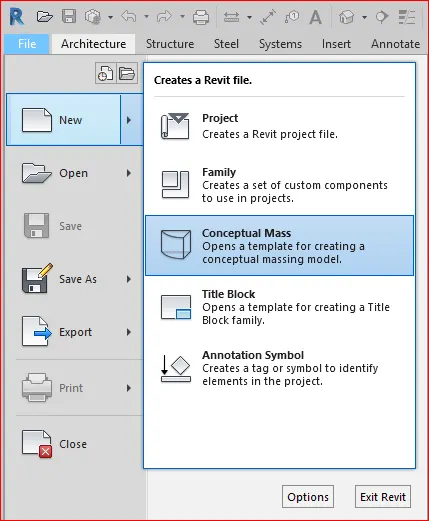
- Click on NEW and create a new conceptual mass.
STEP 2
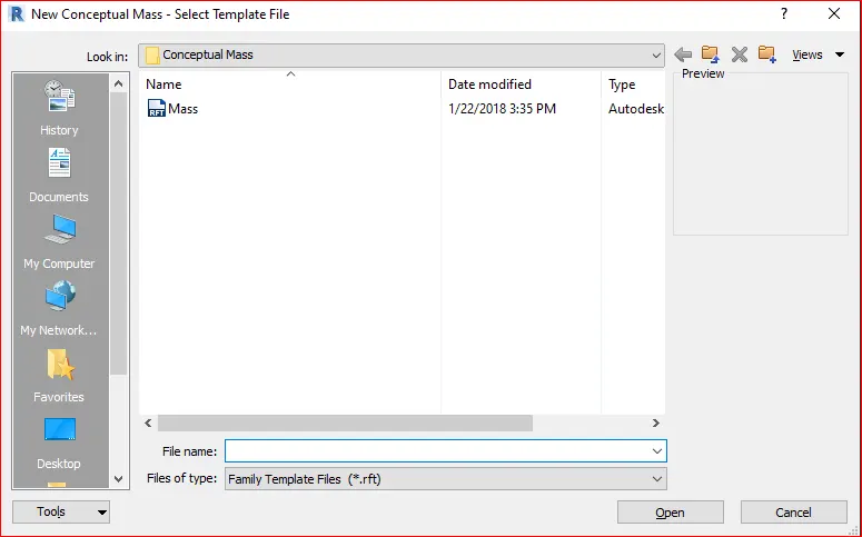
- A library of conceptual mass is open select the mass and open it .
STEP 3
- A cnceptual mass file is open as shown.
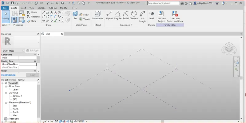
STEP 4
- Go to the elevation and select the level and create a one more level at the distance of 10' from the level 1.
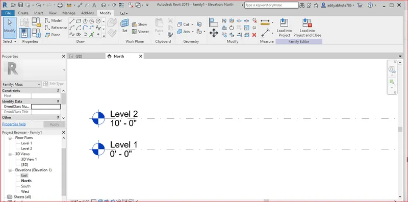
STEP 5
- Now click on create using the spline tool in the modify panel draw the outline
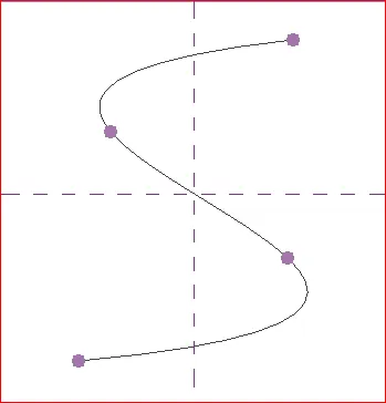
STEP 6
- Go to the 3d view and create a profile to sweep.
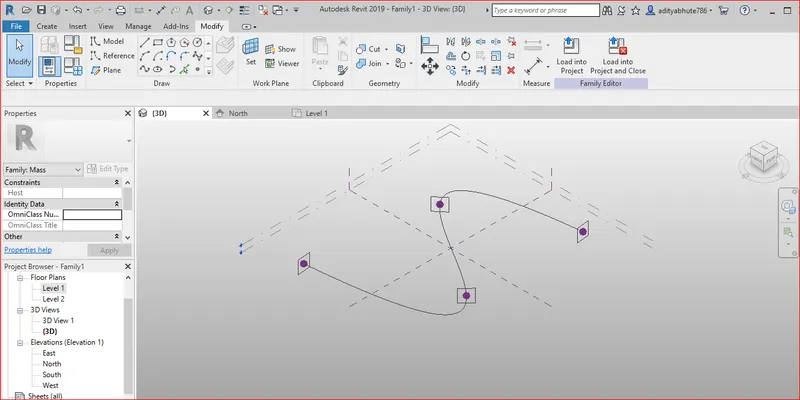
STEP 7
- Surface is created next which was done using sweep,

STEP 8
- Seelect the form and go to the properties and select the pattern as traingular bend.
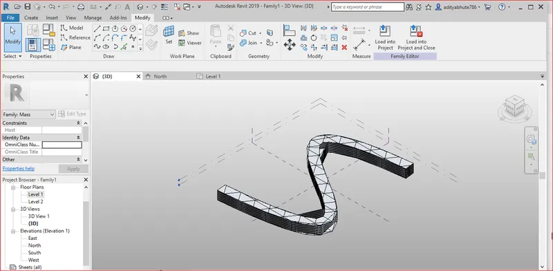
RESULT -
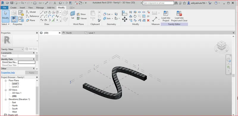
TASK 5) Use Dynamo to work on developing a Parametric Stadium. List your parameters and use the visual programming approach to complete the modeling, You can use the concepts discussed in the parametric high-rise tower in class for reference.
PROCEDURE
STEP 1
- Go to the Window search box to open a Revit workspace.
- In the window search bar type REVIT, and the icon of the Revit application will show on the screen
- Click on the icon of REVIT, the application of Revit will open and the user interface of Revit will show on the screen.
- Click on NEW and create a new architectural template.
STEP 2
- The Dynamo window opens and clicks on the new to create a new file.
STEP 3
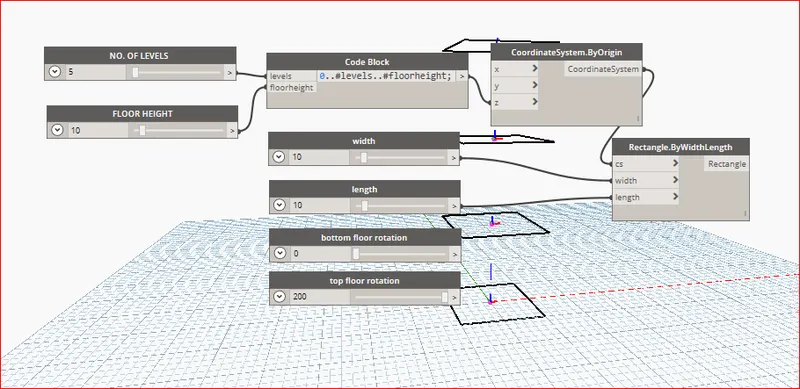
- Insert two integer slider for levels and floor height change the name as shown.
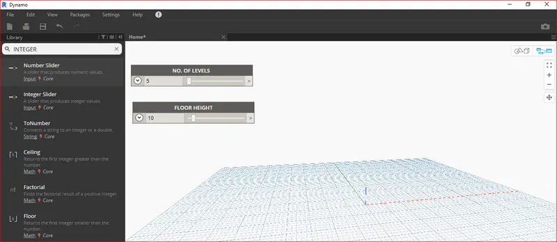
STEP 4
- Insert the code block and write the parameter as 0..#levels..#floorheight and connect with the integer slider.
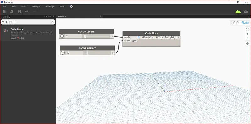
STEP 5
- Insert the coordinateed system by origin from the library
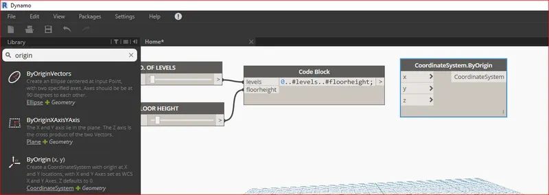
STEP 6
- Connect with the code block
- Again insert the four integer slider for width, lenght, bottom floor rotation, top floor rotation.
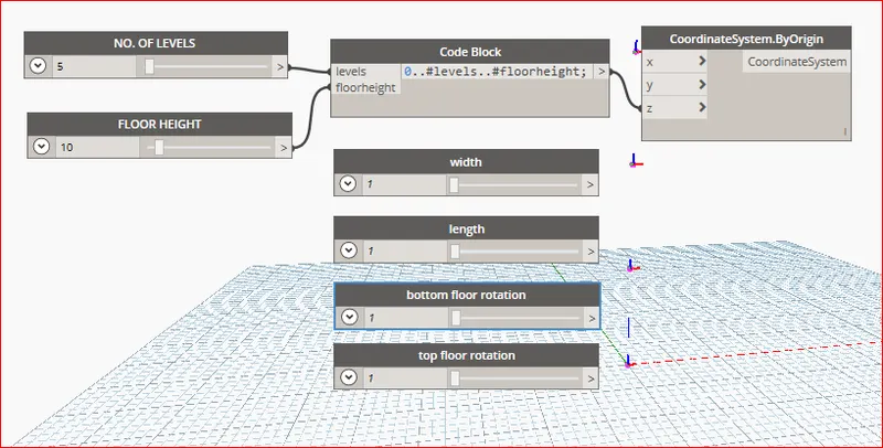
STEP 7
- TO create aa rectangle insert the rectangle by width length and asign all the parameters created in the last step.
STEP 8
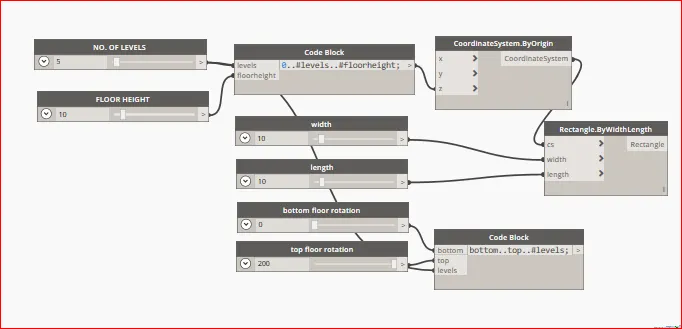
- Insert thee code block and assign the top and bottom rotaion angle
STEP 9
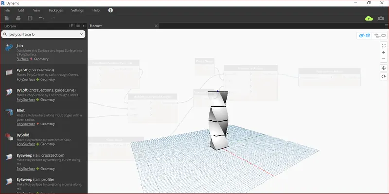
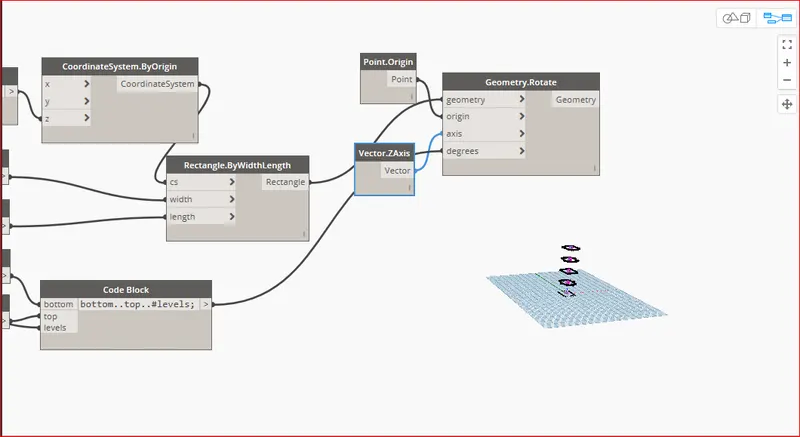
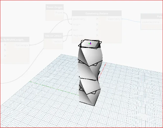
- To create a geometry insert 3 box point origin, vector z axis, and geometry rotate and assign all the properties.
STEP 10
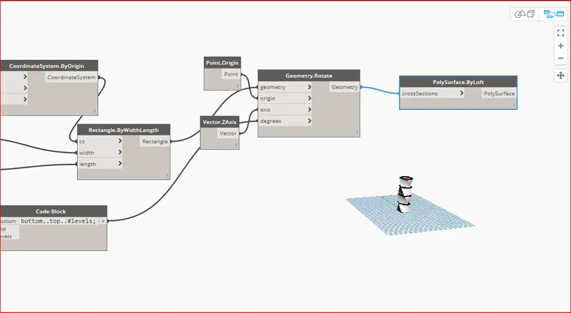
- Insert a new box as polysurface by loft and connect with the geometry box.
STEP 11
- The geometry is rotated with the desired angle with the surafcee loft
RESULT -