Creating Bar Bending schedule, Different Door types, and Creation of standard drawing templates using AutoCad
- Aim: To create template naming as Custom1_titleblock and Custom2_titleblock and save it as a block.
Procedure:
Drawing of Custom1_titleblock
- Type QNEW in command box, press enter, and select default setting as metric.
- Type UN in command box, press enter, select decimal with precision 0.0 as unit of measurement.
- Make sure ortho mode is on.
- Type L in command box, press enter and draw horizontal line.
- By joining start end of line draw the vertical line in downward direction.
- Type O in command box, press enter, specify offset distance 7 units and take offset in downward direction to drawn horizontal line.
- Similarly draw the OFFSETS to downward direction.
- Also draw the vertical line of length from horizontal line in downward direction.
- take offset of right direction from the just drawn vertical line.
- Similarly draw the vertical lines wherever required.
- Type ST in command box, press enter.
- Select the font name as Arial, specify height as 5 units and select apply.
- Type MTEXT in command box and press enter.
- Specify first corner point and opposite corner point.
- Type the text as per required content.
- Type CO in copy the text at the required position.
- Type ED in command box, press enter, select the text required to edit and edit it as per required content.
- Type the ATTDEF in command box and press enter,
- Attribute definition dialog box will open, type tag as TITLE, prompt as what is the title name?, default value as TITLE, text style as style 1, select ok and place the attribute at the required position.
- Similarly define the attribute and insert them at appropriate position as per requirement.
- Type B in command box and press enter block definition dialog box will open.
- Type name as Custom1_titleblock.
- Select the convert to block radio button and select on select object icon on dialog box, select the first geometry, and press enter.
- Click on pick point button on dialog box and select the point as corner of title block and select ok.
Drawing of Custom2_titleblock
- For drawing of table, type L in command box, press enter, and draw a horizontal line.
- Type O in command box, press enter, specify offset distance and take two offsets in downward direction to drawn horizontal line.
- Again, using line tool join the start ending points of three drawn horizontal line.
- Type ST in command box, press enter.
- Select the font name as Arial, specify height as 5 units and select apply.
- Type MTEXT in command box and press enter.
- Specify first corner point and opposite corner point.
- Type the text as per required content.
- Type CO in copy the text at the required position.
- Type ED in command box, press enter, select the text required to edit and edit it as per required content.
- Type the ATTDEF in command box and press enter,
- Attribute definition dialog box will open, type tag as SITE, prompt as what is the site?, default value as SKILL-LYNC NAME, text style as style 2, select ok and place the attribute at the required position.
- Similarly define the attribute and insert them at appropriate position as per requirement.
- Type B in command box and press enter block definition dialog box will open.
- Type name as Custom2_titleblock.
- Select the convert to block radio button and select on select object icon on dialog box, select the first geometry, and press enter.
- Click on pick point button on dialog box and select the point as corner of title block and select ok.
Result:
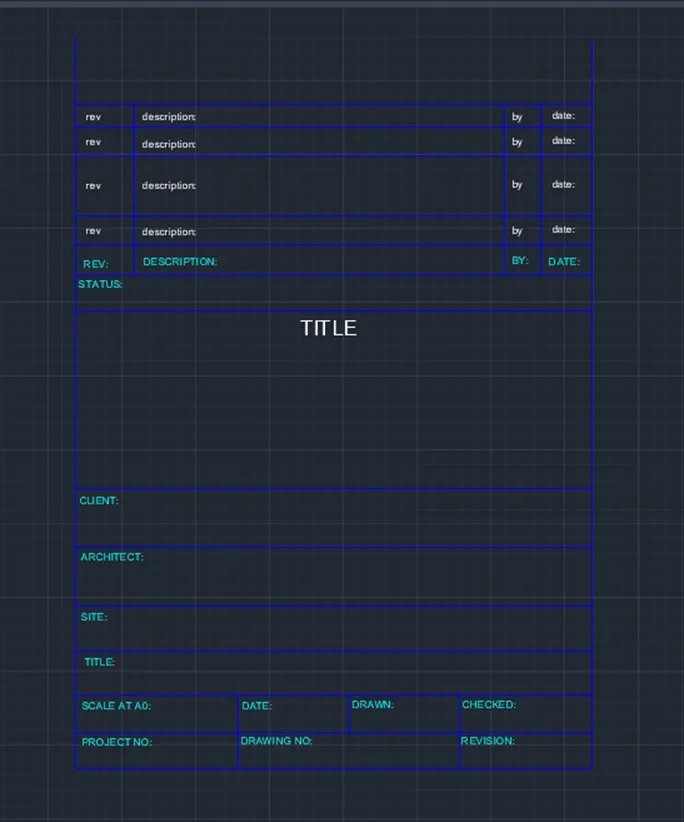
Custom1_titleblock using AutoCAD software by using above mentioned procedure is shown below.
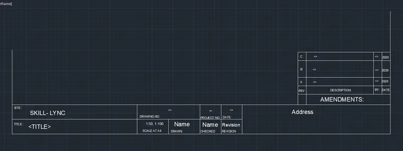
Custom2_titleblock in AutoCAD software by using above mentioned procedure is shown below.
- Aim: To create the doors type for warehouse as a block.
Procedure:
- Type QNEW in command box, press enter, and select default setting as metric.
- Type UN in command box, press enter, select decimal with precision 0 as unit of measurement.
- Type LA in command box, press enter, create the new layer naming as door, assign it the color and set it as current layer.
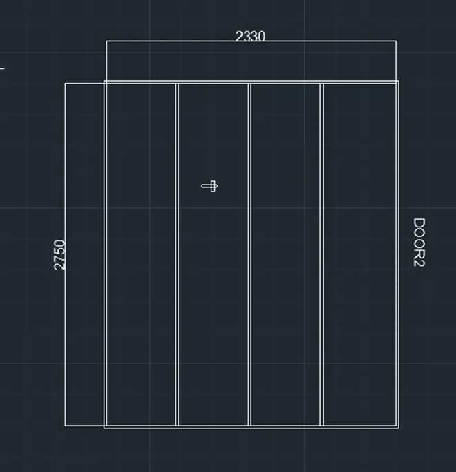
- Type REC in command box, press enter, select the dimension option, specify length as 2330 and width as 2750 units and draw the rectangle.
- Type explode in command box, press enter and select the rectangle to explode it.
- Type O in command box, press enter and take offset to top and bottom horizontal edge of rectangle in inner sides.
- Similarly, take offset of 180 units in left direction to the vertical line in right direction.
- Take offset of 50 units in inner side to the left edge of rectangle followed by offset of 5 units in inner sides to the remaining edges of rectangle in the inner side.
- Type divide in command box, press enter, select the top horizontal line and press enter.
- Type DDPTYPE in command box, press enter and change point style which is easily visible.
- Draw the lines passing through the points inside the rectangle.
- Draw the handle using line and rectangle tool.
- Type B in command box and press enter block definition dialog box will open.
- Type name as warehouse door 2.
- Type CO in command box, press enter, select the entire drawing, press enter, select the base point and copy it to another position.
- Place the rectangle at top middle portion of first division.
- Draw the inclined lines using line tool wherever required.
- Type CO in command box, press enter, select the inner rectangle, press enter, select the base point as top left corner of rectangle, select the array option from command box, enter no of items as 4, press enter, select the fit option from command box, select the second point as end point of top horizontal line.
- Again, type CO in command box, press enter, select the top series of three inner rectangle, press enter, select the base point as top left corner of rectangle, select the array option from command box, enter no of items as 3, press enter, select the fit option from command box, select the second point as end point of left vertical line.
- Type B in command box and press enter block definition dialog box will open.
- Type name as warehouse door 1.
- Select the delete radio button and select on select object button on dialog box, select the first geometry, and press enter.
- Click on pick point button on dialog box and select the point as midpoint of left edge of rectangle and select ok.
Result:
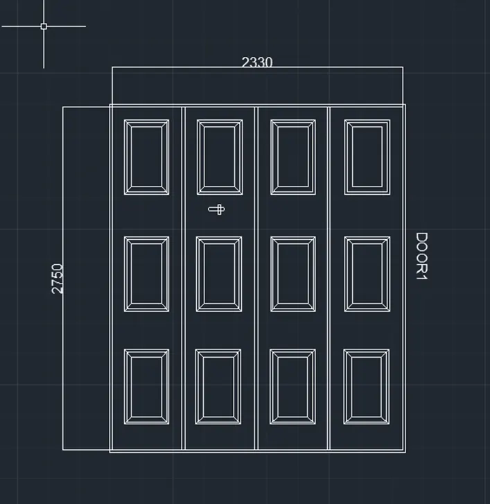
Door type for warehouse door 2 and door 1 are created using AutoCAD software by following the above-mentioned procedure as shown below.
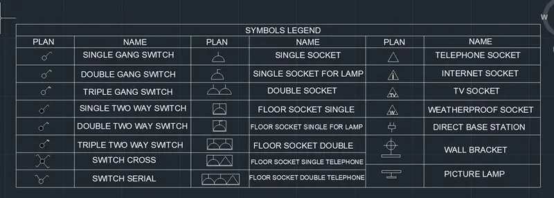
- Aim: to create electrical legend
a) Creating electrical symbols:
i) Single gang switch: draw a circle and with line draw an incline line vertical line and horizontal line perpendicular to the inclines as required.
ii) Double gang switch: Draw circle and draw two horizontal lines and a vertical incline line.
iii) Triple gang switch: Draw circle, 1 vertical line and three horizontal lines.
- iv) Single two way switch: draw same as single gang switch and with donut command give internal dia as zero.
- v) Double two way switch: draw same as double gang switch and create donut.
- vi) Triple two way switch: draw same as triple gang create donut.
vii) Switch cross: create a circle and donut inside and with line command draw an incline vertical and perpendicular horizontal and mirror the line in both direction.
viii) Switch serial: copy the switch cross and delete two bottom lines, remove the donut also.
- ix) Single socket: Create a circle, divide it into half and draw a line a line at the top.
- x) Single socket for lamp:from the single socket,draw a horizontal line perpendicular to vertical.
- xi) Double socket: draw the single socket and copy it to create and place it.
xii) Floor socket single: draw a rectangle surrounding single socket.
xiii) Floor single socket for lamp: draw a rectangle surrounding single socket for lamp.
xiv) Floor socket double: create two single socket and place a rectangle surrounding it.
- xv) Floor socket single telephone: draw a single socket, a triangle and surrounded by a rectangle.
xvi) Floor socket double telephone: draw 2 single socket and a triangle surrounded by a rectangle.
xvii) Telephone socket: draw a triangle.
xviii) Internet socket: insert text "i" in the triangle.
xix) Tv socket: insert text"TV" in the triangle.
- xx) Weatherproof socket: insert text"w" in the triangle.
xxi) Dect base section: draw a rectangle,delect the bottom grip point,select add vertex and then pull the vertext to create a bend and with lines draw the lines.
xxii) Wall bracket: with rectangular draw the base,create a circle,draw a line connecting the rectangle and circle,draw a cross line inside the circle.
xxiii) Picture lamp: Draw two rectangles connected bya line.
- b) Creating them as block:
- Give command B and give name as single gang switch,pick a point,select object,tick scale uniformly and allow exploding options.
- Similarly define each one of them as block giving the respective names.
- c) Creating and arranging them in layers:
- First create a rectangular table having 10 rows and 6 columns.
- Place each of the blocks in the respective rows and columns.
- To enter text with the block from the insert tab,select field,select object and finally select block.
- Place the text in the respective rows.
- Similarly place all the title inside the legends.
Result:
- Aim: to draw the doors of residential project and create it as a block.
Procedure:
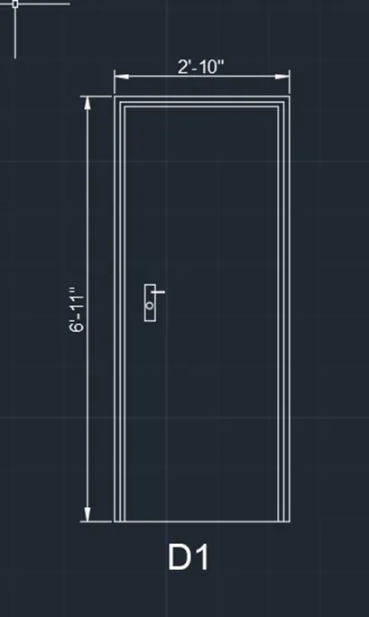
- a) D1-2'10"x6'11"
- Draw a rectangle with dimension as 2'10"x6'11".
- Draw offset 1.5" for frame then 1" for shutter.
- Draw lock by two rectangle perpendicular to each other and fillet the corners with radius 0.1" circle.
- Write the text by multiline text"D1".
- Create it as a block "B" give name as type-D1- pick a corner point,select the object and then block is created.
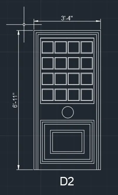
- b) D2-3'4"x6'11"
- Draw a rectangle with dimension as 3'4"x6'11".
- Draw offset 1.5" for frame then 1" for shutter.
- Draw rectangle for panel
- Copy the 3 rectangle to 4 rows.
- For the second panel draw a rectangle
- Draw another rectangle inside it of.
- Draw lock by circle in between the two panels.
- Write the text by multiline text "D2".
- Create it as block"B" give name as "type-D2" pick a corner point ,select object.
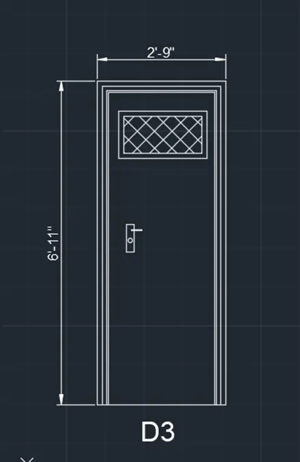
- c) D3-2'9"x6'11"
- Draw a rectangle of 2'9"x6'11".
- Offset 1" for thickness,2" offset for frame and offset 1.5" as shutter thickness.
- Draw a rectangle at the top for ventilation and give offset 1" for thickness.
- Hatch the rectangle.
- Create it as a block-give name as type d3-pick point,select object,tick scale uniformly and explode all.
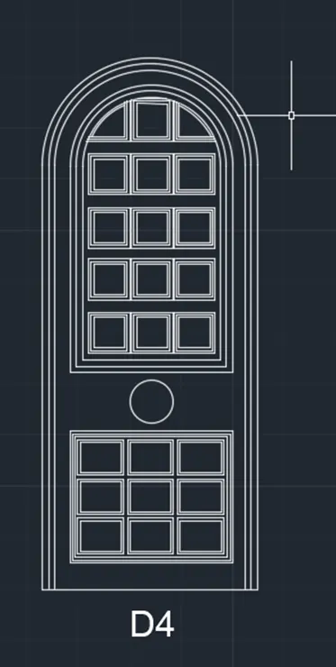
- d) D4
- Draw a rectangle.
- Explode it create an arc with 2 point method with both point as the endpoints.
- Offset the arc and the line with 1.5" and then offset 1".
- Offset 8" from arc and rectangle for panel and divide it into two.
- Take 1" offset 2 times to show thickness.
- Create the rectangle inside the panel.
- Make it as a block,name it as D4-pick a point and select object tick the uniform scale and explde all.
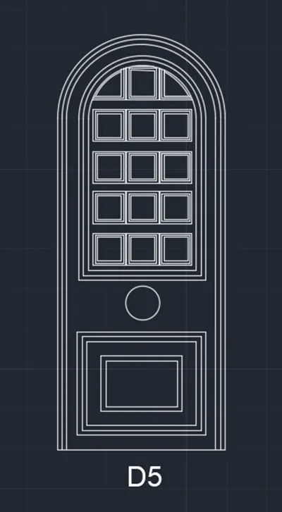
- e) D5
- Draw a rectangle.
- Offset 1.5" for frame and 1" as shutter thickness.
- Create another rectangle.
- Create another rectangle on the bottom.
- Offset 1" two times for both the rectangles.
- Create the rectangle inside for panels wit offset 0.5".
- Create it as block give name as type D5-pick point, select object, tick scale uniformly and explode all.
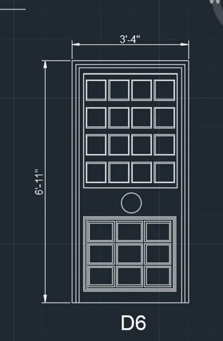
- f) D6
- Draw a rectangle.
- Explode it and create an arc with 2 point method with both point as the endpoints.
- Offset the arc and the line with 1.5" an then 1" for the frame.
- Offset from arc and rectangle for panel divide it into two.
- Take offset from arc and rectangle for panel and divide it into two.
- Take 1" offset 2 times to show the thickness on top figure bottom rectangle.
- Create rectangles inside the top panel,3 rows and 4 columns.
- For bottom panel offset the rectangles.
- Make it a block, name as type D6, pick a point and select the object tick the dialogue box of uniform scale and explode all.
Result: the doors are created and are made into blocks.
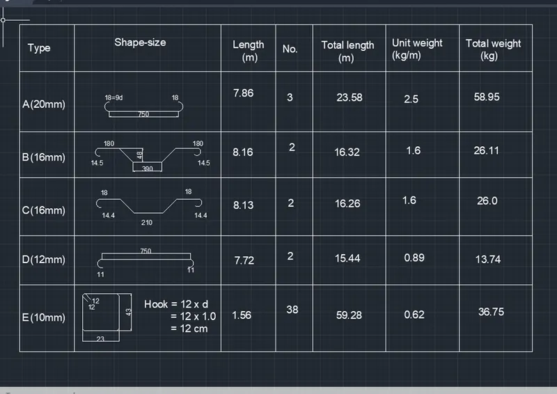
- Aim: to create bar ending schedule and insert it as block.
Procedure:
- a) Drawing each shape:
A-20mm
- Draw a line of 750cm for straight bar.
- Create arc for the bend.Create on one side and mirror it on another side.
B-16mm
- Draw a line of 300mm for straight bar.
- Draw vertical line of 41 cm and extend a horizontal line and draw a line inclined at 45 degree from the base of vertcial line upto horizontal line.
- Trim off the extra lines usong trim command.
- Copy the same on the other side.
- Draw a horizontal line of 139cm and copy it on other side.
- Draw bend with arc and mirror the same on the other side.
C-16mm
- Draw a line of 210cm.
- Draw vertical line of 41 cm and extend a horizontal line and draw a line inclined at 45 degree from the base of vertical line up to horizontal line.
- Trim off the extra lines using trim command.
- Copy the same on the other side.
- Draw a horizontal line of 180cm and copy it on other side.
- Draw bend with arc and mirror the same on the other side.
D-12mm
- Draw a line of 750cm for straight bar.
- Draw an arc downwards.
- Copy it on the other side.
E-10mm
- Draw a rectangle of 23cm and 43cm.
- Fillet the corner with fillet radius 5cm.
- Draw two line of 120cm.
- b) Creating each of them as block:
- Command "B" give name as A-pick a point, select object, select delete, tick scale uniformly and explode all.
- Similarly create 5 blocks: A,B,C,D,E and insert each of the bars as blocks.
- c) Inserting it in table:
- Create a table with rectangle and divide it into 6 rows and 7 columns.
- With multiline text enter type, shape size, length no, total length, unit weight, total weight.
- By insert command insert each of the block in respective columns.
Result: