Creating Bar Bending schedule, Different Door types, and Creation of standard drawing templates using AutoCad
Aim: To create:
Template, inserting text and attributes
Doors of warehouse and placing it in blocks
Electrical legend and making it blocks
Different types of door for residential project
Drawing bars, making it as block and making it as a table as bar bending schedule.
Commands Used in this challenge:
Line
Rectangle
Offset
Trim
Explode
Circle
Dimlinear
Move
ATTDEF
BATTMAN
Block
Blockedit
able
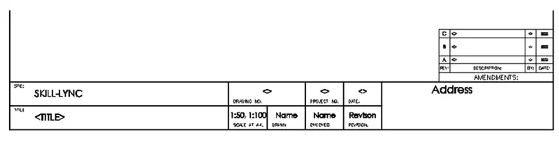
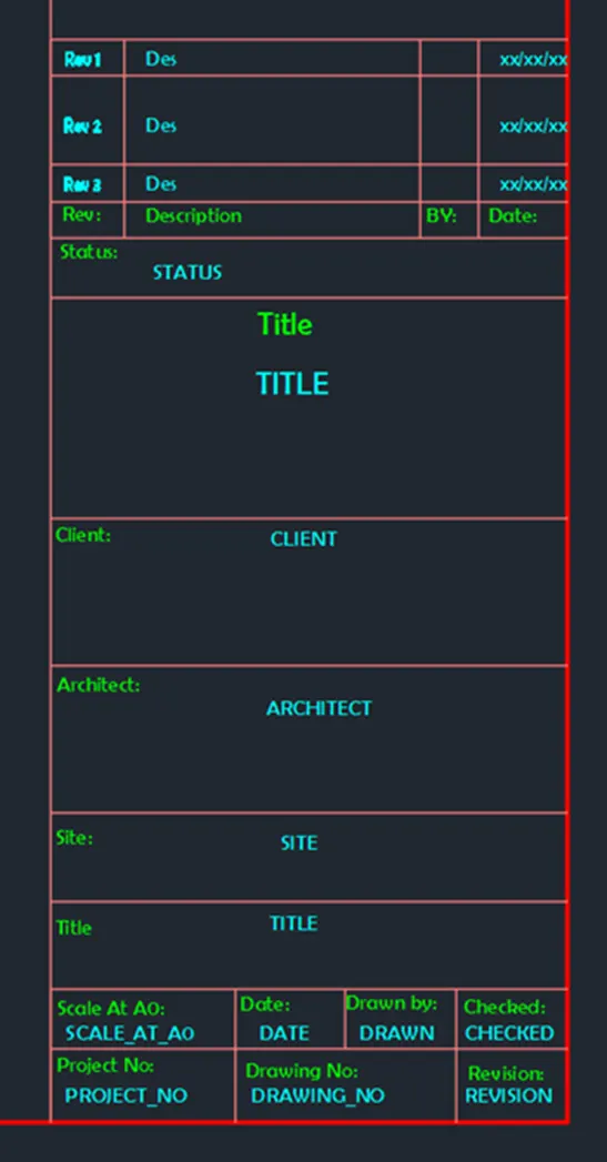
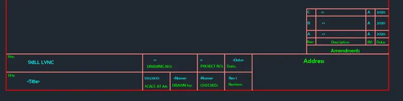
1. Create the templates as shown in Figures. Take the size of the title block as per industry standards or you can assume it as per the size of the paper. Use text and attributes wherever required. After creating the title block you need to save it as a block with names: Custom1_titleblock and Custom2_titleblock, respectively.
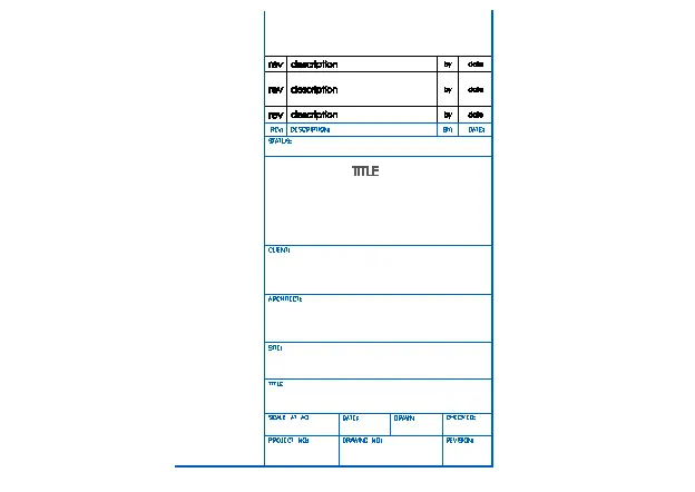
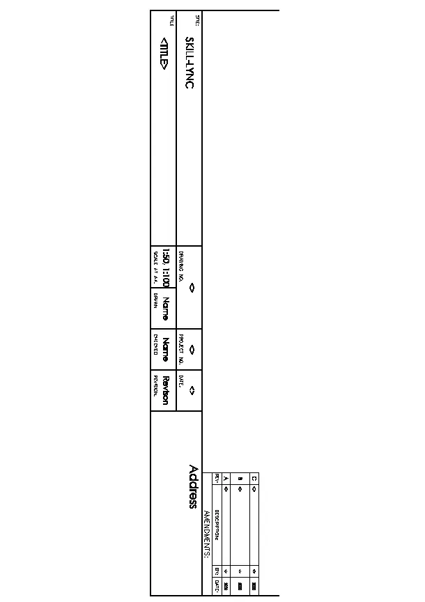
Aim: To create the templates Custom1_titleblock and Custom2_titleblock as shown in the figure
Introduction: The tittle block is a template created in a sheet which contains the information or data regarding the drawing and also the information of the company and persons of the company responsible for the drawing. The given title blocks custom1 and 2, one with vertical title block at the right and another the bottom of the page. The tittle block contains information regarding the revision number of the drawings, title of the drawings, names of the persons involved in making of the drawing.
Procedure:
Open AutoCAD
In Startup settings start from scratch select metric (Meter)
Open grid and snap settings
Change snap and grid spacing to 100
Change major line every grid line to 10
Turnoff adaptive grid
Type ‘un’ in command box and press enter
Change units’ type to decimal and precision to 0.00 and insertion scale to millimeters
Change ‘limits’ to (0,0) and (420,297)
Step 1: Creating Layers
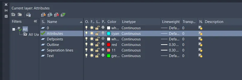
Open Layer properties and create new layers by clicking on new layer or right click on any layer and select new layer to create new layer
Layers are created as follows
Step 2: Creating Custom_tittleblock_1:
Change current layer to Outline
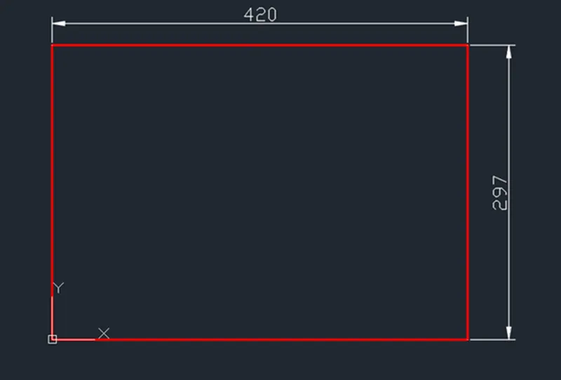
Draw a rectangle of dimensions 420mm length and 297mm as the size of an A3 sheet as shown in figure
Select the rectangle drawn and explode the rectangle
Offset the right edge to a distance of 70mm to the left
Change the layer of the offset line to Separation lines and to current layer
Draw a line the bottom edge from bottom right corner to the offset line bottom end
Offset:
Offset the line drawn earlier to a distance of 10mm to the top
Offset the last offset line to a distance of 8mm to the top
Offset the last offset line to a distance of 12mm to the top
Offset the last offset line to a distance of 12mm to the top
Offset the last offset line to a distance of 20mm to the top
Offset the last offset line to a distance of 20mm to the top
Offset the last offset line to a distance of 30mm to the top
Offset the last offset line to a distance of 8mm to the top
Offset the last offset line to a distance of 5mm to the top
Offset the last offset line to a distance of 5mm to the top
Offset the last offset line to a distance of 12mm to the top
Offset the last offset line to a distance of 5mm to the top
Draw a line to connecting the ends of top five offset lines
Offset the line drawn earlier to a distance of 10mm to the right
Offset the last offset line to a distance of 40mm to the right
Offset the last offset line to a distance of 8mm to the right
Repeat the same procedure at the bottom part of tittle block
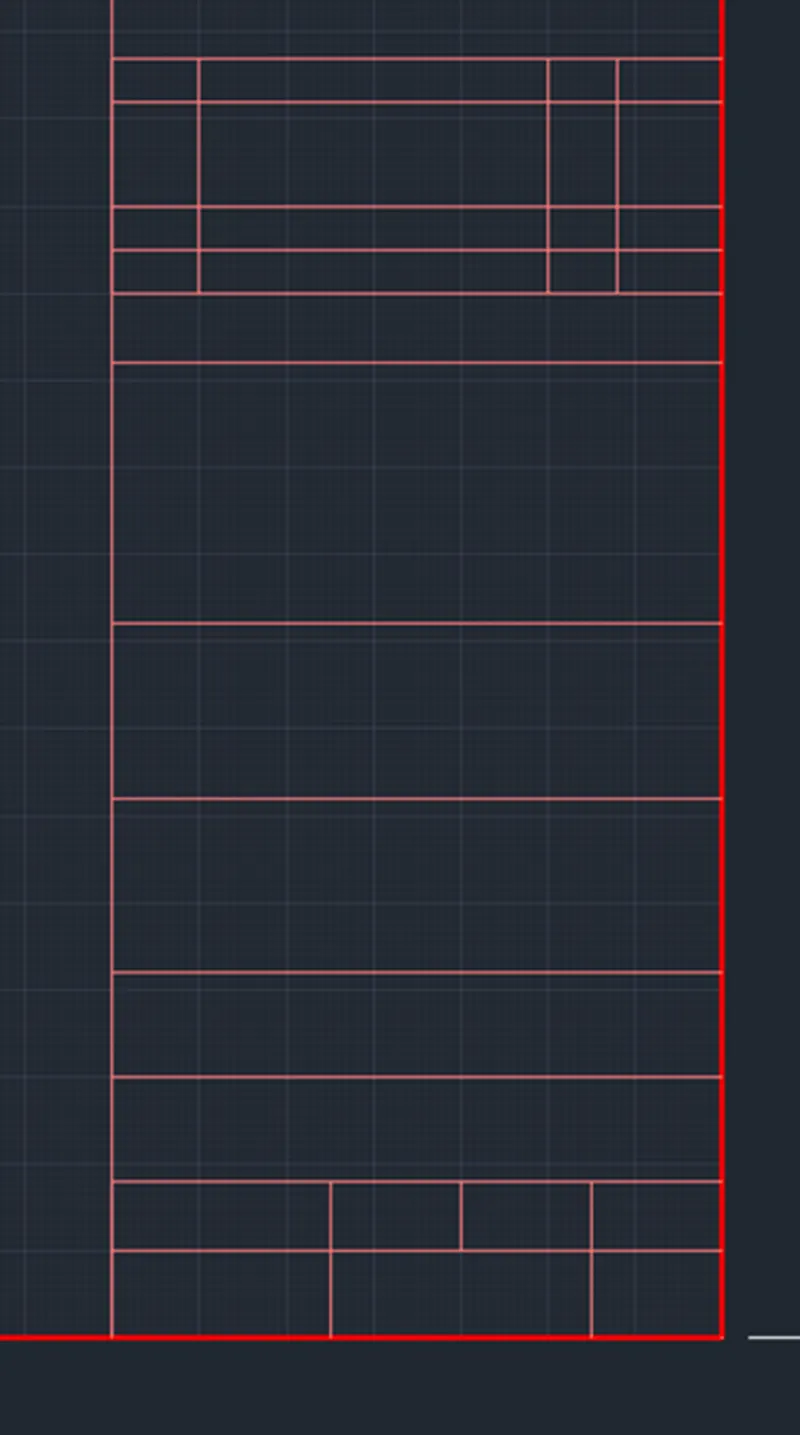
Result of the above step is as follows
Step 3: Adding attributes to Custom_tittleblock_1:
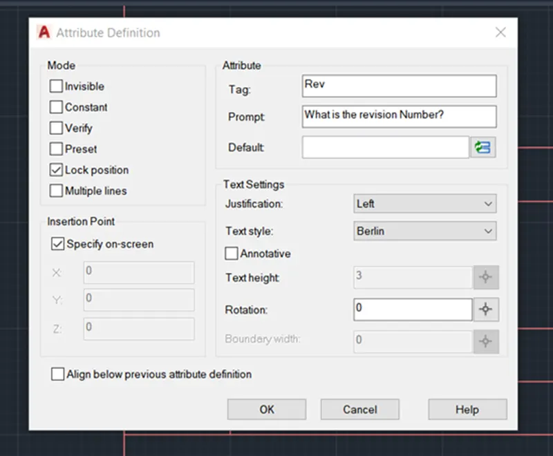
Go to insert tab and click on define attribute in block definition palette or type ATTDEF in command box
In the popup box
Set mode as ‘lock position’
Set tag as ‘Rev’
Set Prompt as ‘What is the revision number?’
Set default as ‘Rev 1’
Set justification as ‘left’
Text style as per drawing text style ‘Berlin Sans FB’ and press okay
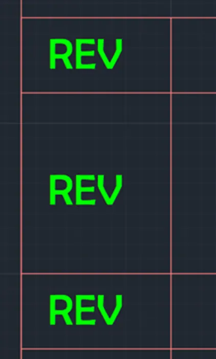
Place the attribute at the top left box in table at the top of title box
Copy the same to rest of similar attributes
After adding required text the table is as follows
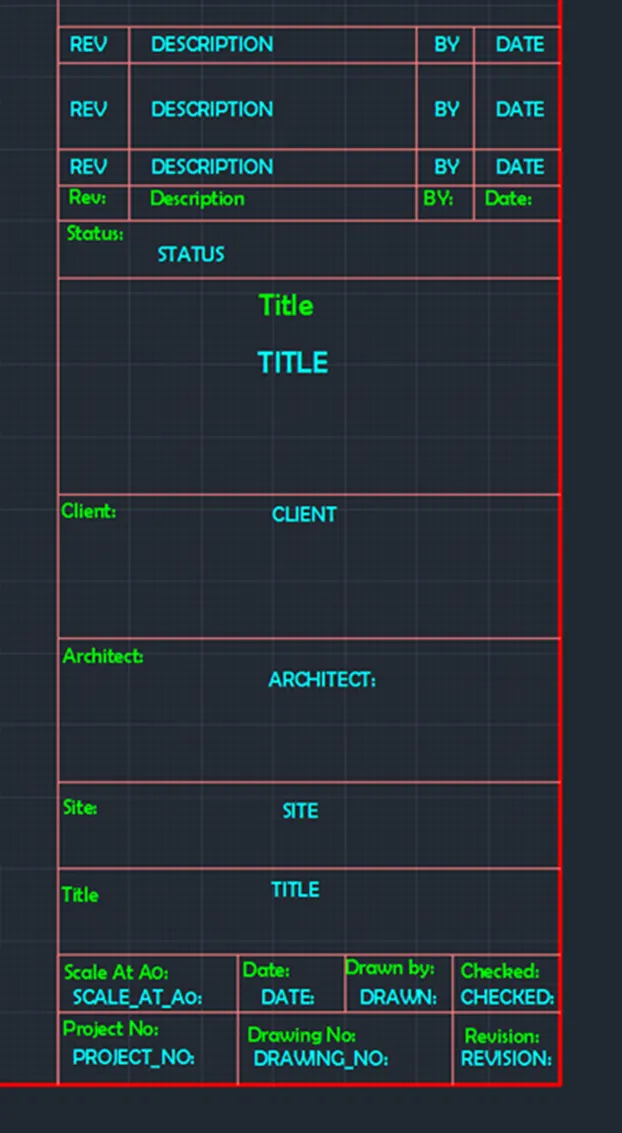
Follow similar procedure to all the attributes and the final result is shown below
Step 4: Creating Block
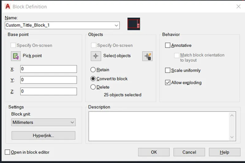
Go to insert tab and click on create block in block definition palette or type block in command box
In the popup box
Set name as ‘Custom_Tittleblock_1’
Pic base point as bottom left corner
Click on select object and select the entire contents of the drawing
Click on convert to block
Click on allow exploding
Set Block units to ‘millimeters’
Click ‘ok’
Step 5: Creating Custom_tittleblock_2:
Change current layer to Outline
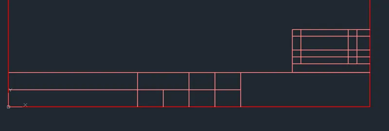
Draw a rectangle of dimensions 420mm length and 297mm as the size of an A3 sheet as shown in figure
Select the rectangle drawn and explode the rectangle
Offset the bottom edge to a distance of 20mm to the top
Offset the last offset line to a distance of 20mm to the top
Change the layer of the offset lines to Separation lines and to current layer
Draw a line connect midpoints of the offset lines
Offset the line drawn above two times to both left and right to a distance of 30mm
Trim off unnecessary lines
Draw a rectangle of size 90mmX50mm as shown in the figure
Select the rectangle drawn above and explode the rectangle
Offset the bottom edge to a distance of 10mm to the top
Offset the last offset line to a distance of 8mm to the top
Offset the last offset line to a distance of 8mm to the top
Offset the last offset line to a distance of 16mm to the top
Offset the left edge to a distance of 10mm to the right
Offset the right edge to a distance of 15mm to the left
Offset the last offset line to a distance of 10mm to the left
Step 6: Adding attributes to Custom_tittleblock_2:
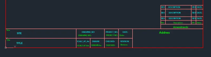
Go to insert tab and click on define attribute in block definition palette or type ATTDEF in command box
In the popup box
Set mode as ‘lock position’
Set tag as ‘Site’
Set Prompt as ‘What is the site location?’
Set default as ‘SKILL LYNC’
Set justification as ‘left’
Text style as per drawing text style ‘Berlin Sans FB’ and press okay
Place the attribute at the top left box in table at the top of title box
Copy the same to rest of similar attributes
Follow similar procedure to all the attributes and the final result is shown
Step 7: Creating Block
Go to insert tab and click on create block in block definition palette or type block in command box
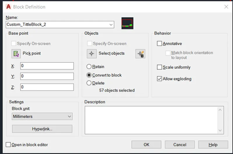
In the popup box
Set name as ‘Custom_Tittleblock_2’
Pic base point as bottom left corner
Click on select object and select the entire contents of the drawing
Click on convert to block
Click on allow exploding
Set Block units to ‘millimeters’
Click ‘ok’
Result:
The result consists inserting the respective custom title blocks 1 and 2 and their complete block drawings. After creating the blocks in step 4 and 7 then while inserting the blocks where ever required, a popup appears asking for the information of the attribute to be displayed in the block. If not given any information to the attributes, it will display the default value given while creating the attribute.
All the dimensions mentioned are in millimeters
Dimensions and text are assigned using dimension layer and text layers
Custom_titleblock_1:
Custom_titleblock_2:
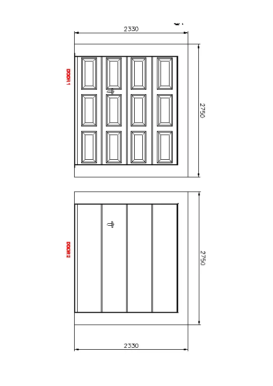
2. Create the doors type for warehouse as shown in the Figure. You need to create each door type as per standard size or given dimensions. Create the blocks of this door type after creating them.
Aim: To create the door types 1 and 2.
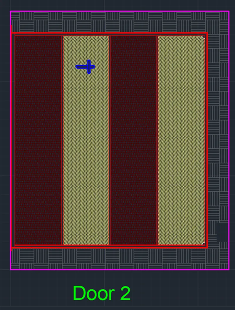
Introduction: Two door types are given, both with same dimensions. First door type as projection or shapes on top of it along with door handle and door frame. Second door type is normal four panel double swing door with handle and door frame.
Procedure:
Open AutoCAD
In Startup settings start from scratch select metric (Meter)
Open grid and snap settings
Change snap and grid spacing to 100
Change major line every grid line to 10
Turnoff adaptive grid
Type ‘un’ in command box and press enter
Change units’ type to decimal and precision to 0.00 and insertion scale to millimeters
Step 1: Creating Layers
Open Layer properties and create new layers by clicking on new layer or right click on any layer and select new layer to create new layer
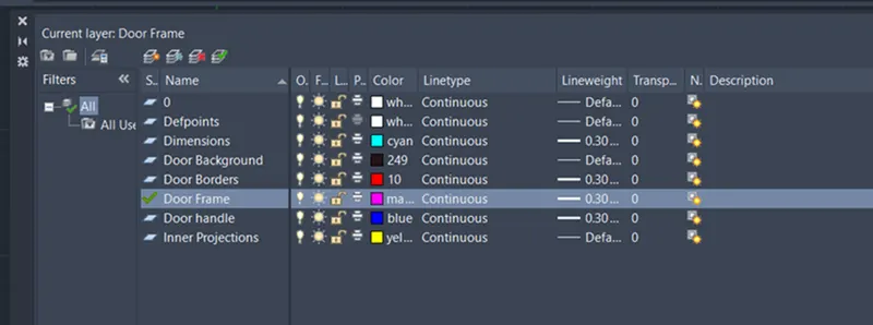
Layers are created as follows
Step 2: Creating Door 1:
Change the current layer to door frame
Draw a rectangle of dimensions 2330mmX2750mm
Select the rectangle drawn above and type explode and press enter
Offset the top, right, and bottom edges to the inside of rectangle to a distance of 230mm
Change the layer of the offset lines to door borders
Draw a line connecting the left ends of top and bottom offset line
Move the line to a distance of 10 to right
Trim off extra portions
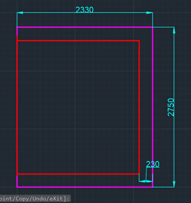
Using join command join top, right and bottom edges of the door borders drawn above
Offset the polyline of door borders to inside to a distance of 10
Offset the last offset line to a distance of 20 to the inside
Explode the inner offset polyline
Using divide command, divide the top edge of exploded polyline in to 4 segments
Change pdmode value to 3
Drawn perpendicular lines to the opposite edge from these points
Offset each line to both right side and left side to a distance of 10mm, including all the edges of the inner box
Delete the center lines
Offset each vertical offset line to both right side and left side to a distance of 50mm, including the left and right edges of the inner box
Select one of the divide lines drawn and divide that line into 3 segments
Drawn perpendicular lines to the opposite edge from these points
Offset these lines to top and bottom to a distance of 42.5mm.
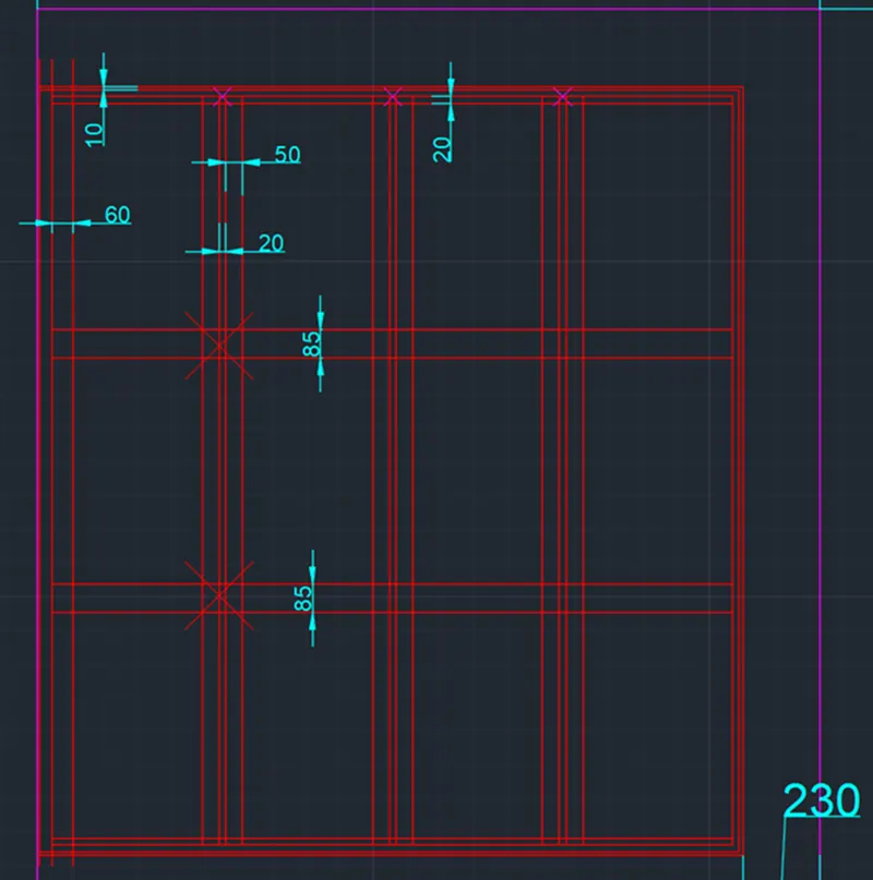
After offset of the lines take the dimensions of the inner box area
Change the current layer to ‘Inner projections’
Using those dimensions create a rectangle at any point on the screen
Offset the rectangle to a distance of 20mm to inside
Offset the offset rectangle to a distance of 50mm to inside
Draw line connect all the top left corners of all the rectangles and at all corners
Convert the final draw to a block using block command with top left corner as base point
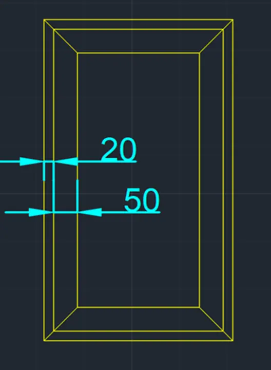
Change the current layer to ‘Door handle’
Draw door handle using rectangle command, 2-point circle command and trim command as follows
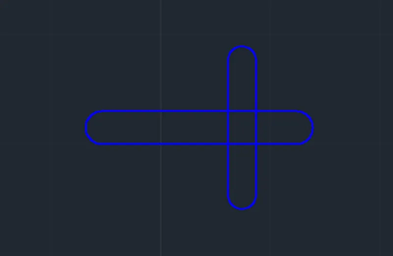
The final drawing of door 1 is shown in the result
Step 3: Creating Door 2
Change the current layer to door frame
Draw a rectangle of dimensions 2330mmX2750mm
Select the rectangle drawn above and type explode and press enter
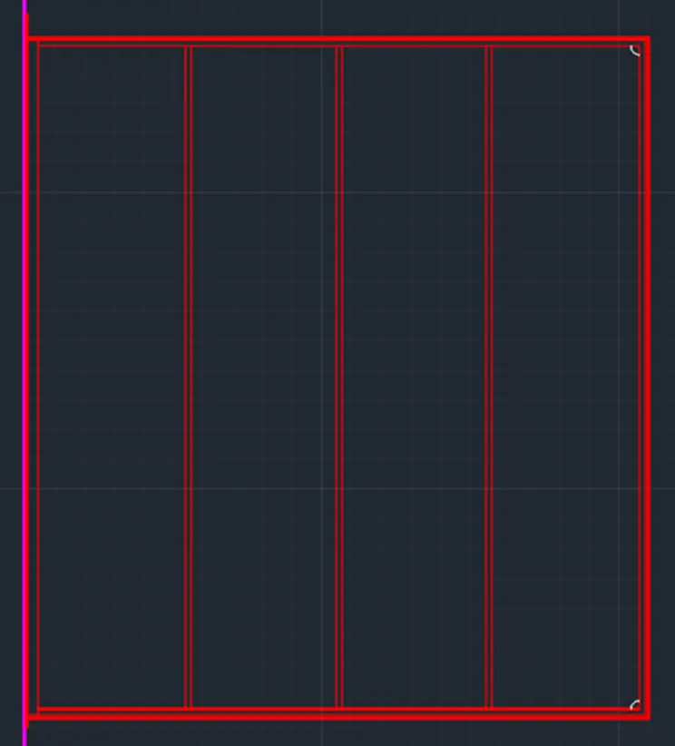
Offset the top, right, and bottom edges to the inside of rectangle to a distance of 230mm
Change the layer of the offset lines to door borders
Draw a line connecting the left ends of top and bottom offset line
Move the line to a distance of 10 to right
Trim off extra portions
Using join command join top, right and bottom edges of the door borders drawn above
Offset the polyline of door borders to inside to a distance of 10
Offset the last offset line to a distance of 20 to the inside
Explode the inner offset polyline
Using divide command, divide the top edge of exploded polyline in to 4 segments
Change pdmode value to 3
Drawn perpendicular lines to the opposite edge from these points
Offset each line to both right side and left side to a distance of 10mm, including all the edges of the inner box
Delete the center lines
Change the current layer to ‘Door handle’
Draw door handle using rectangle command, 2-point circle command and trim command as follows
The final drawing of door 1 is shown in the result
Result:
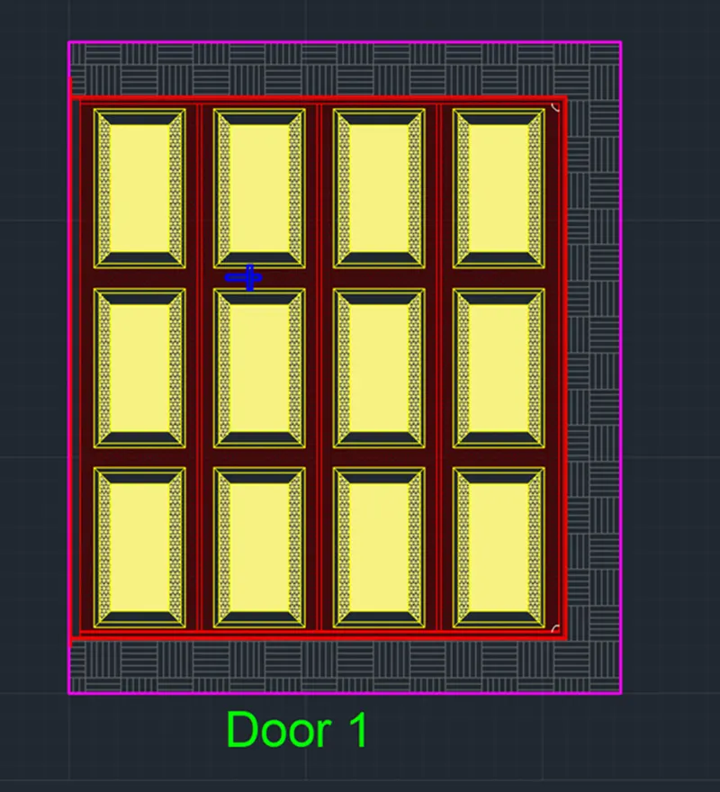
The result consists of two door types, door 1 and 2. Layers are created at the beginning of the challenge and are assigned before drawing of a component. The door types are made as per the drawings given and addition hatching is done with random hatch patterns and colors. The inner projections of door 1 and the door handle in both doors are drawn separately and then copied to the source. The two door types are show below after hatching the doors and door frames.
All the dimensions mentioned are in millimeters
Dimensions and text are assigned using dimension layer and text layers
Door 1
Door 2:
3. Create each symbol as a block with the name given in the legend. After creating the blocks arrange them in the legend as shown in the Figure.
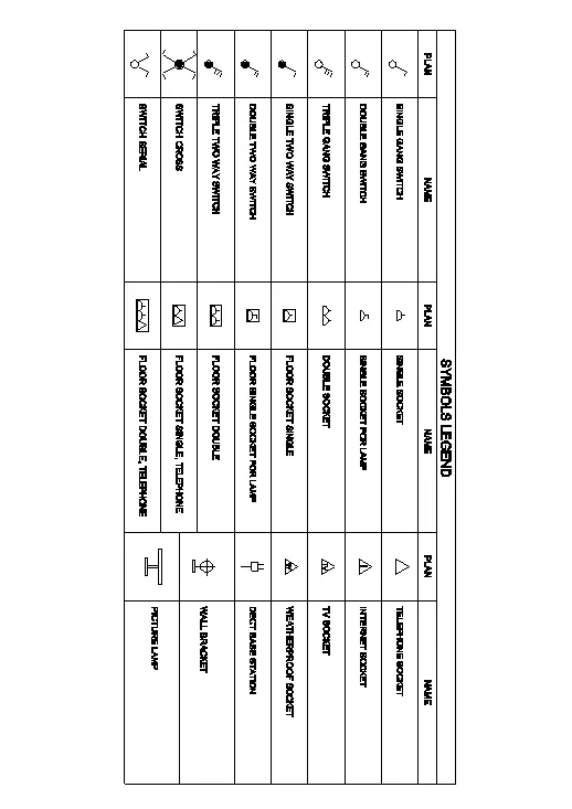
Aim: To create the blocks and legend as shown in figure
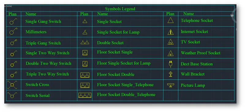
Introduction: The legend given consists plan of the electrical component along with the name of the component. First blocks are created using plan views and respective names. Then the legend is prepared using field box command in which object and object name are selected.
Procedure:
Open AutoCAD
In Startup settings start from scratch select metric (Meter)
Open grid and snap settings
Change snap and grid spacing to 100
Change major line every grid line to 10
Turnoff adaptive grid
Type ‘un’ in command box and press enter
Change units’ type to decimal and precision to 0.00 and insertion scale to millimeters
Step 1: Creating Layers:
Open Layer properties and create new layers by clicking on new layer or right click on any layer and select new layer to create new layer
Layers are created as follows
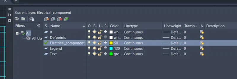
Step 2: Creating Blocks
Block as initially created using draw command from the tool bar
All the blocks are created using Electrical component layer
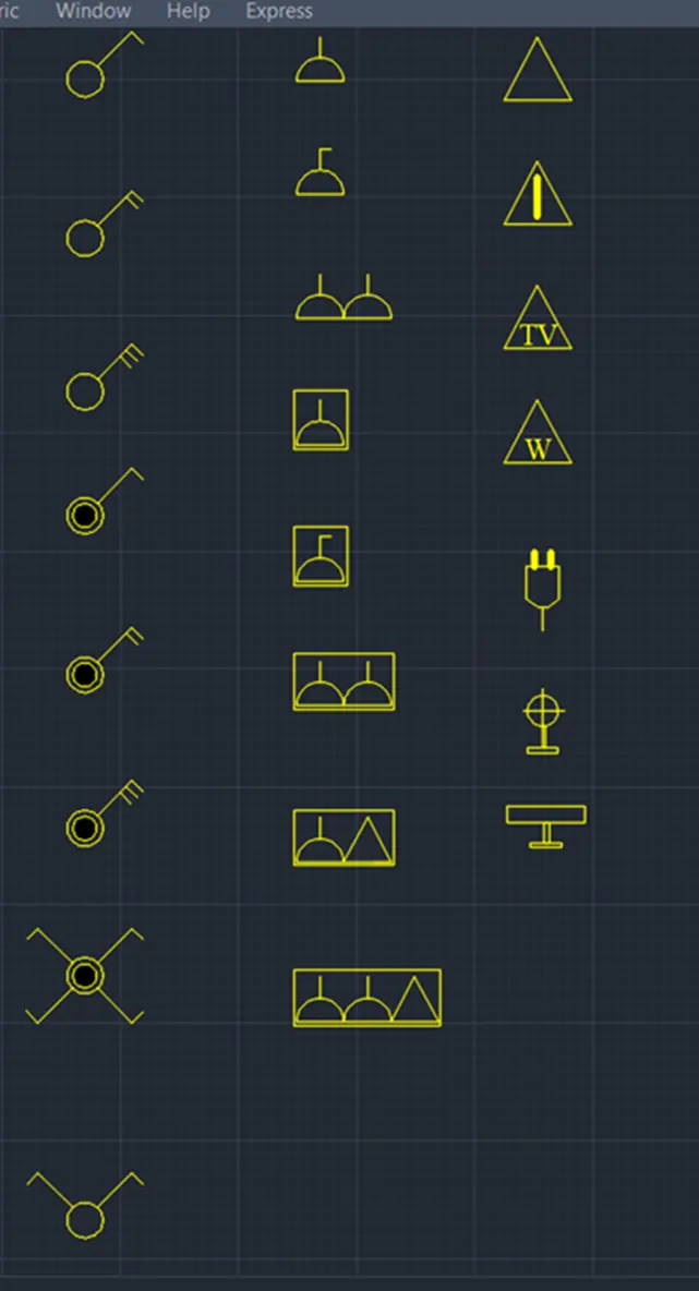
Each component is made into a with its respective name as shown in figure
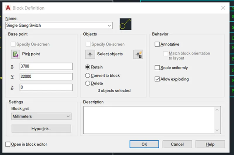
Go to insert tab and click on create block in block definition palette or type block in command box
In the popup box
Set name as ‘Single Gang Switch’
Pic base point as center of circle
Click on select object and select the entire contents of the drawing
Click on convert to block
Click on allow exploding
Set Block units to ‘millimeters’
Click ‘ok’
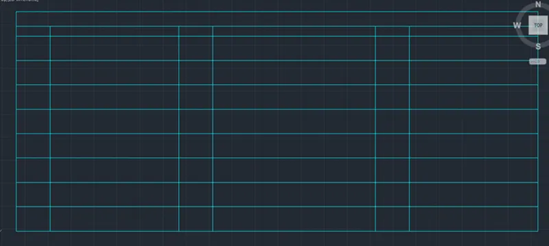
Step 3: Creating Legend
Create a rectangle of size 22000mmX9500mm
Explode the rectangle using rectangle command
Offset the top edge to a distance of 1000mm to bottom
Offset the last offset line to a distance of 500mm to bottom
Offset the last offset line to a distance of 1000mm to bottom
Offset same until the bottom edge
Using divide command, divide the top edge into three segments
Draw the line connecting two lines to the bottom edges
Offset the lines drawn to right to distance of 1500mm
Step 4: Adding Blocks and Field Boxes
Add All the blocks into respective boxes
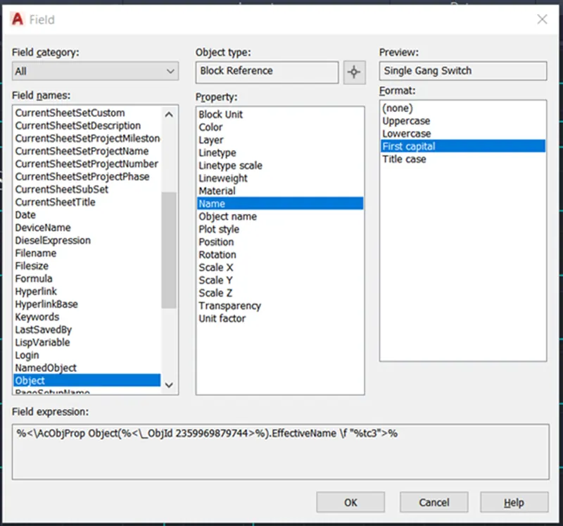
Go to Insert tab and click on field box
In popup box go to Object category
Click on select object and select the object required
Set format as first capital
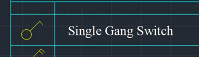
Click on ok and place the text in box next to the block
Result:
The result consists of an electrical legend created from the figure. Initially blocks are created using commands. Then table is drawn using line command and offset. Add blocks and field boxes respectively. The layers are assigned respectively.
All the dimensions mentioned are in millimeters
Dimensions and text are assigned using dimension layer and text layers
4. Create the door type for residential building as a block. Save the name of the blocks as type. Use given dimensions or assume dimensions as per industry standards.
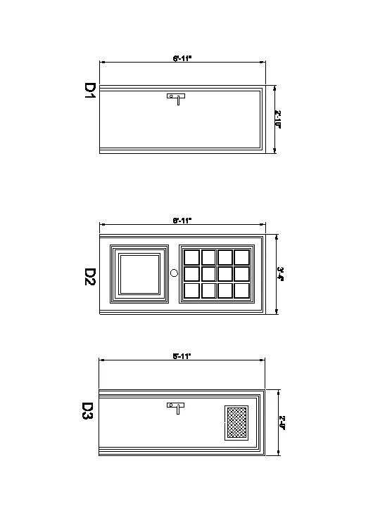
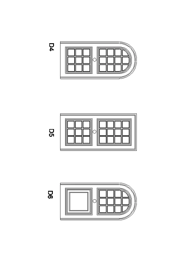
Aim: To create the door type 1 to 6 as shown in the figures.
Introduction: Two door types are given, both with same dimensions. First door type as projection or shapes on top of it along with door handle and door frame. Second door type is normal four panel double swing door with handle and door frame.
Procedure:
Open AutoCAD
In Startup settings start from scratch select Imperial (Feet and Inches)
Open grid and snap settings
- Change snap and grid spacing to 1’
- Change major line every grid line to 10
- Turnoff adaptive grid
Type ‘un’ in command box and press enter
Change units’ type to decimal and precision to 1’1/16” and insertion scale to inches
Step 1: Creating Layers
Open Layer properties and create new layers by clicking on new layer or right click on any layer and select new layer to create new layer
Layers are created as follows
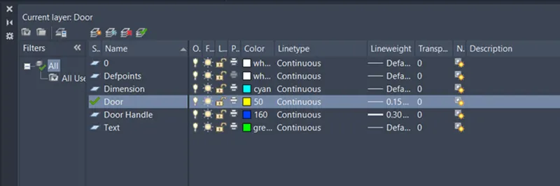
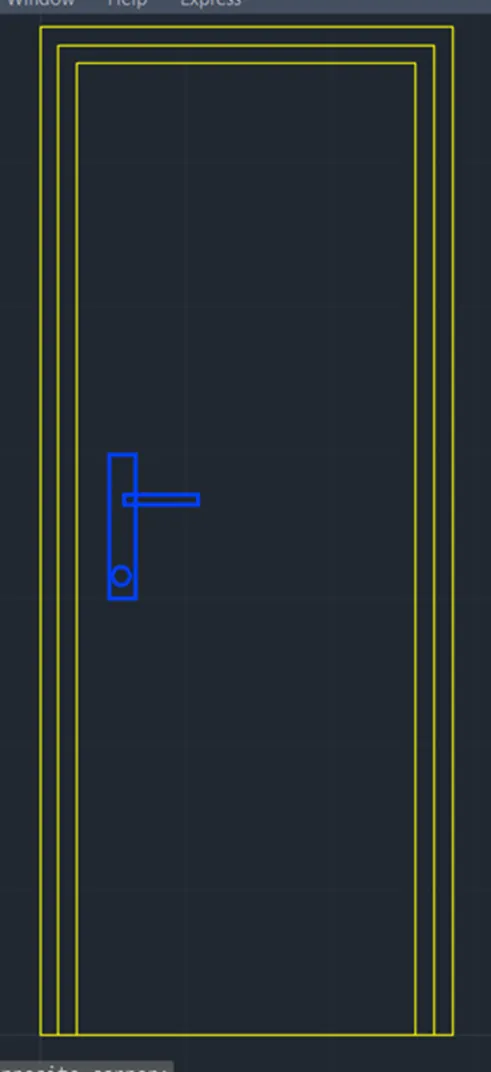
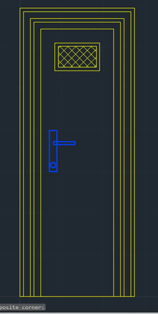
Step 2: Creating Door 1
Change the current layer to door
Draw a RECTANGLE of dimensions 2’10”X6’11”
Select the rectangle drawn above and type EXPLODE and press enter
Select the top, right, and left edges and type JOIN and press enter
Offset the top, right, and left edges to the inside of rectangle to a distance of 1.5”
Offset the top, right, and left edges to the inside of rectangle to a distance of 3”
Draw the door handle using rectangle command and circle command as shown in figure.
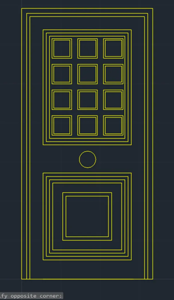
Step 3: Creating Door 2
Change the current layer to door
Draw a RECTANGLE of dimensions 3’4”X6’11”
Select the rectangle drawn above and type EXPLODE and press enter
Select the top, right, and left edges and type JOIN and press enter
Offset the top, right, and left edges to the inside of rectangle to a distance of 1.5”
Offset the last offset pline to the inside of rectangle to a distance of 1”
Draw a rectangle using rectangle command at an offset of 6” from the last offset line
Draw the rectangle offset of 1” to the inside twice.
Draw a rectangle inside of the last offset rectangle and offset the same inside to a distance of 1/2”.
Using rectangular array command draw four rows and three columns
Draw circle just below the rectangle as shown in figure with a radius of 2.5”
Below the circle draw a rectangle leaving 6” offset from the edges
Offset the rectangle inside to the distances of 1” four times, 3”
Step 4: Creating Door 3
Change the current layer to door
Draw a RECTANGLE of dimensions 2’9”X6’11”
Select the rectangle drawn above and type EXPLODE and press enter
Select the top, right, and left edges and type JOIN and press enter
Offset the top, right, and left edges to the inside of rectangle to a distance of 1”
Offset the last offset pline to the inside of rectangle to a distance of 2”
Offset the last offset pline to the inside of rectangle to a distance of 1”
Offset the last offset pline to the inside of rectangle to a distance of 2”
Draw a rectangle at an offset of 4” from the edges and offset the rectangle 1” to inside
Hatch the inner rectangle with hatch pattern ANS137
Draw the door handle similar to the door type 1
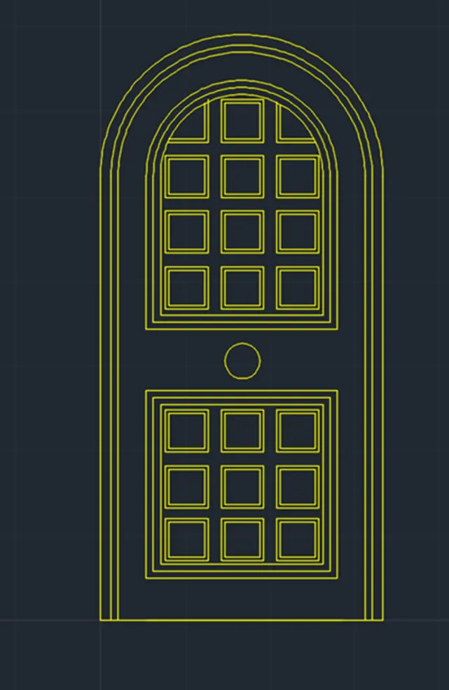
Step 5: Creating Door 4
Create the Door similar to door type 2
Draw a circle with diameter as the width of the door
Trim the circle bottom portion
Offset the circle similar to offset done for the rectangles and trim off the extra portions as shown in the figure
Draw an rectangular array of rectangles done in the top half in the bottom half rectangle too as shown in figure
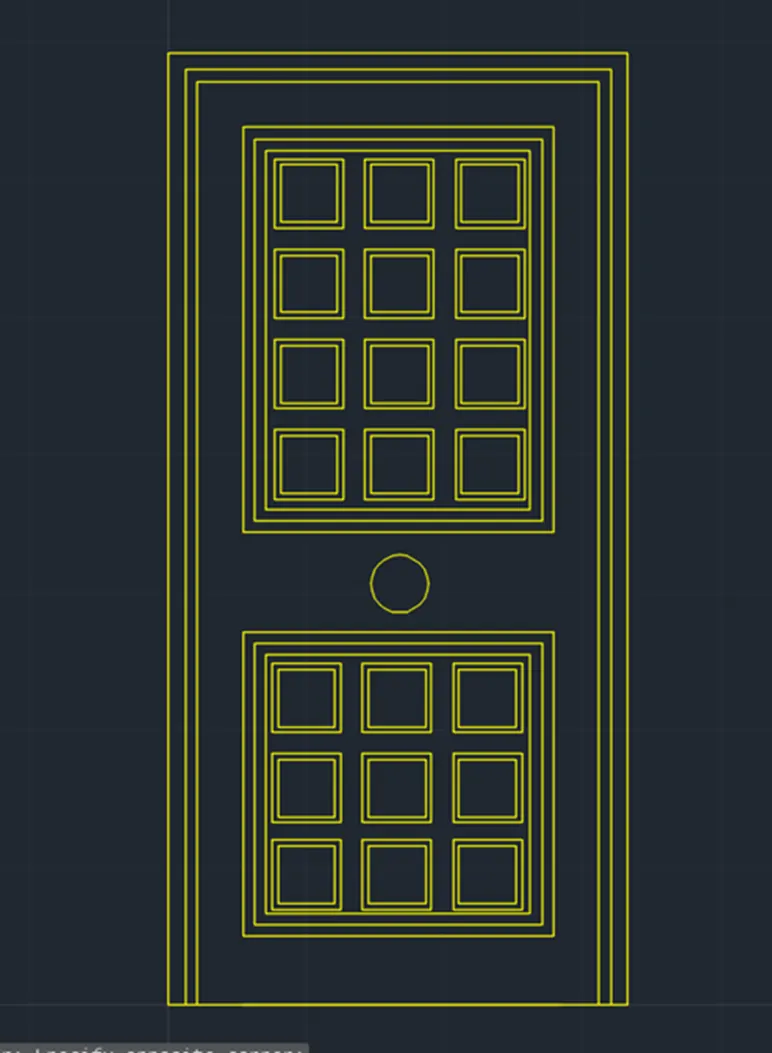
Step 6: Creating Door 5
Create the Door similar to door type 2
Draw an rectangular array of rectangles done in the top half in the bottom half rectangle too as shown in figure
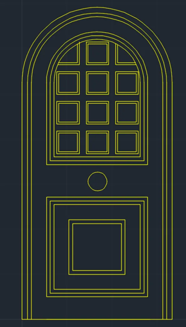
Step 7: Creating Door 6
Create the Door similar to door type 2
Draw a circle with diameter as the width of the door
Trim the circle bottom portion
Offset the circle similar to offset done for the rectangles and trim off the extra portions as shown in the figure
Result:
The result consists of various door types through 1 to 6. Layers are created for door, door handle, text and dimensions. Doors are created through step 2 to step 6 with layers preassigned. The result is divided in to three pictures with two door types in one picture along with dimensions and text.
All the dimensions mentioned are in feet and inches
Dimensions and text are assigned using dimension layer and text layers
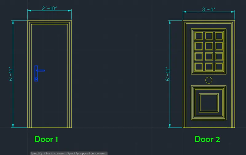
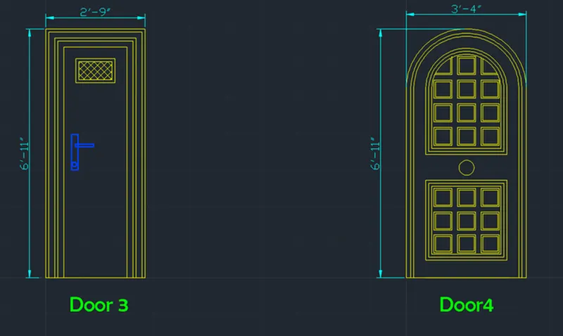
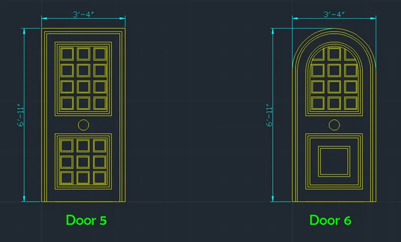
5. Create each shape as a block as shown in the Figure. Save the block and insert them on the table as shown in the Figure.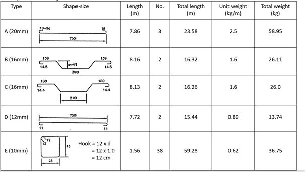
Aim: To create the blocks and reinforcement schedule as shown in figure
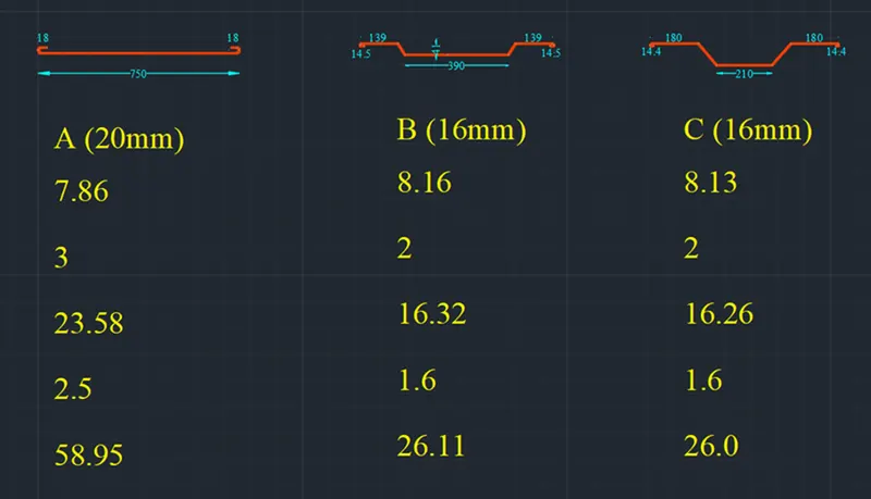
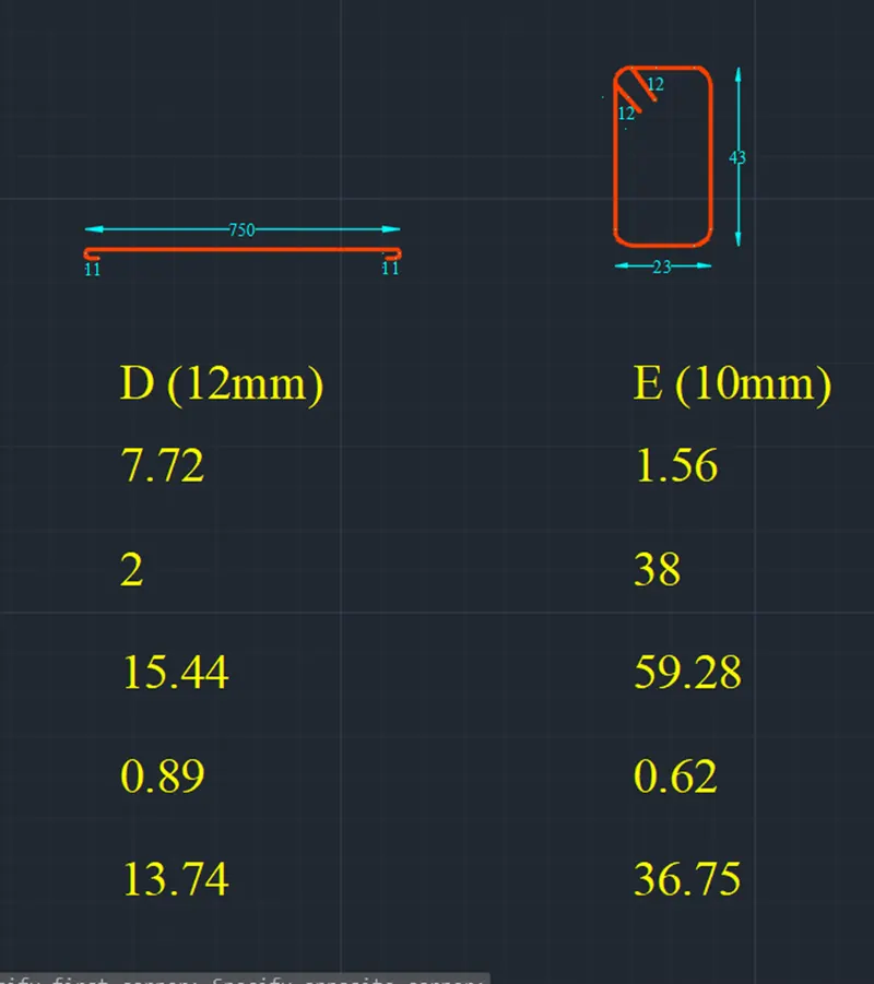
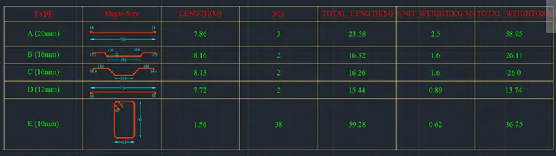
Introduction: The given figure consists of different reinforcement details such as type of reinforcement, number of rebars, dimensions, total length of reinforcement, and weight details of rebars. The aim of this question is creating the rebars using dimensions, covert these rebars to blocks and create the table containing the data.
Procedure:
Open AutoCAD
In Startup settings start from scratch select metric (Meter)
Open grid and snap settings
Change snap and grid spacing to 100
Change major line every grid line to 10
Turnoff adaptive grid
Type ‘un’ in command box and press enter
Change units’ type to decimal and precision to 0.00 and insertion scale to millimeters
Step 1: Creating Layers
Open Layer properties and create new layers by clicking on new layer or right click on any layer and select new layer to create new layer
Layers are created as follows
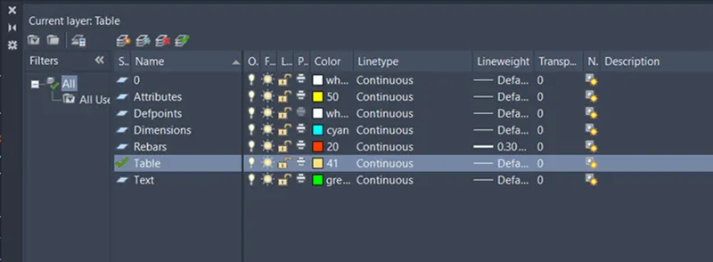
Step 2: Creating Data Attributes
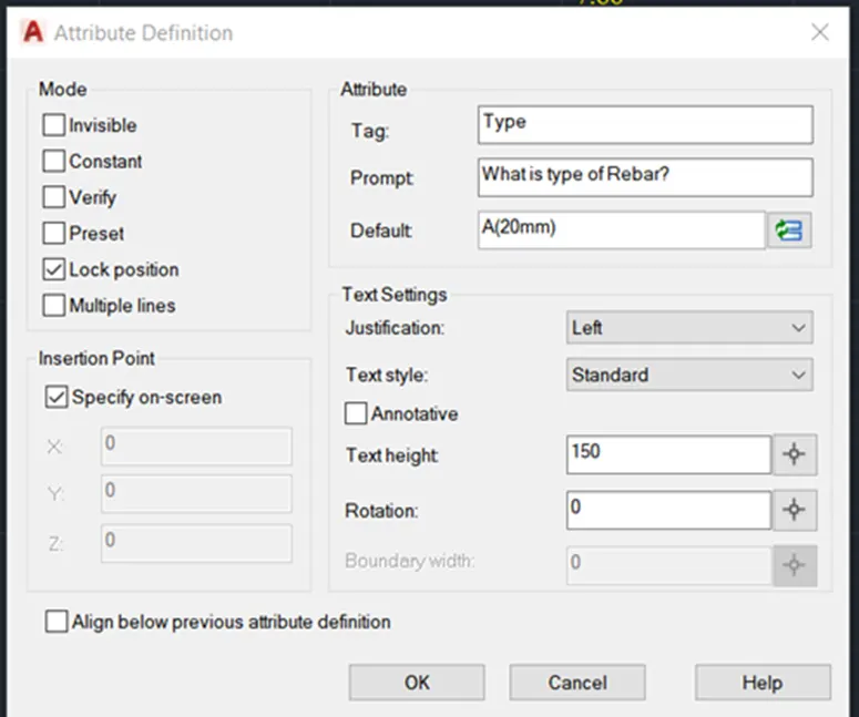
Go to insert tab and click on define attribute in block definition palette or type ATTDEF in command box
In the popup box
Set mode as ‘lock position’
Set tag as ‘Type’
Set Prompt as ‘What is the Type of rebar?’
Set default as ‘A(20mm)’
Set justification as ‘left’
Text style as per drawing text style ‘Times New Roman’ and press okay
Place the attribute at the any point on the screen
For rest of attributes click on ‘Align below previous attribute’.
Follow the same procedure for rest of the attributes
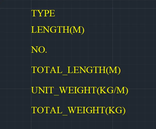
Step 3: Creating Reinforcement
Type A(20mm)
Draw a line at any point on the screen to a distance of 750cm.
Draw the semicircle at both ends for the bend of 18cm to upside
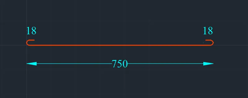
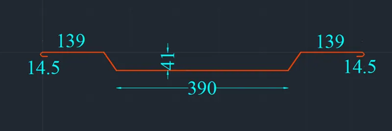
Type B(16mm)
Draw a line at any point on the screen to a distance of 730cm.
Draw the semicircle at both ends for the bend of 14.5cm
Draw a line with the centers coinciding of length 390cm
Move the line down to a distance of 41cm
Draw the inclined shape of bar using line command as shown in figure
Type C(16mm)
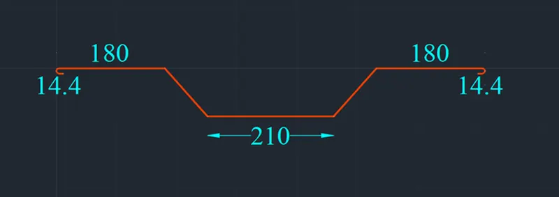
Draw a line at any point on the screen to a distance of 712cm.
Draw the semicircle at both ends for the bend of 14.4cm
Draw a line with the centers coinciding of length 210cm
Move the line down to a distance of 80cm
Draw the inclined shape of bar with horizontal distance of 71.6cm using line command as shown in figure.
Type D(12mm)
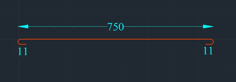
Draw a line at any point on the screen to a distance of 750cm.
Draw the semicircle at both ends for the bend of 11cm to downside
Type E(10mm)
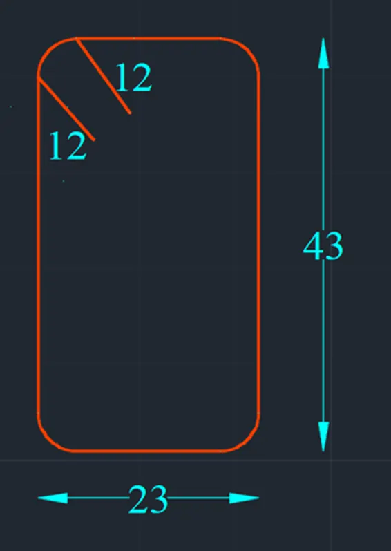
Draw a rectangle with dimensions 230mmX430mm
Fillet the edges with radius of 40mm.
Draw the extended bar fold of size 12cm
After this copy the attributes created in step 1 and paste them below each rebar type
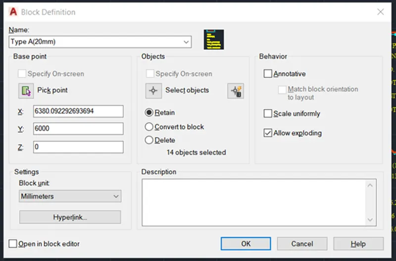
Convert them to block and add the values of attributes while inserting the blocks
Step 4: Creating Data from data extraction
Go to insert tab and click on Extract Data in linking & extraction tool bar
Click on create a new data extraction and press next
Set the location of Data extraction
Click on select objects from current drawing and select all the blocks created and click next
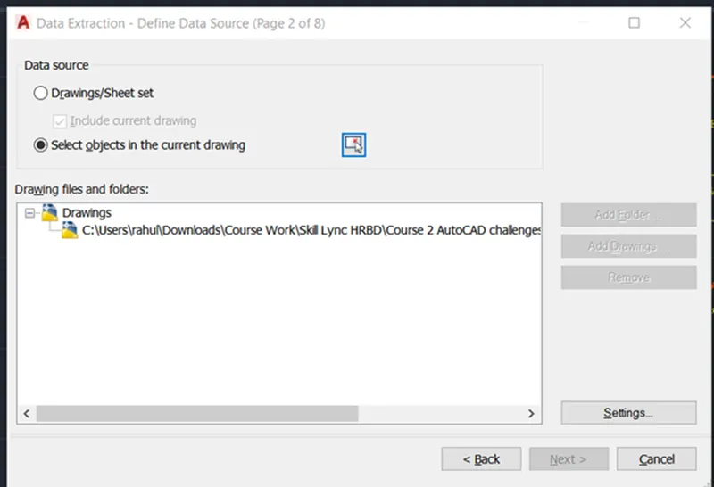
Select only the data that needs to be extracted and click next
Click on only attributes and click next
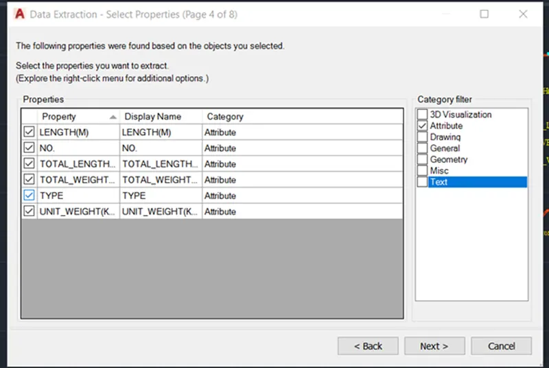
Check the preview and click next
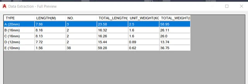
Click on insert data extraction table into drawing and click next
Make the table settings and click next and finish
Step 5: Creating Table
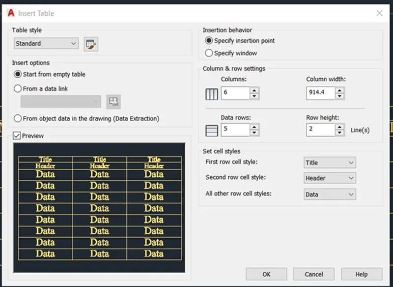
Draw a table from the annotate tool bar
After creating table click on second column and from table creation tool add a column to the left to add figures
Result:
The result of this challenge consists of rebars schedule drawing made from the given figure. Initially layers are created for reference. Then attributes are created for adding data for all types of rebars. Rebars are created as per the dimensions in figure given. Attributes are copied to each of the rebar and created as a block. Then data is extracted from the all the blocks using extract data command. Then all the data is copied to a table along with figures. Result is provided in two pics one with blocks and attributes and in table format
All the dimensions mentioned are in feet and inches
Dimensions and text are assigned using dimension layer and text layers