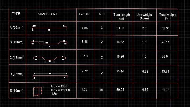
Creating Bar Bending schedule, Different Door types, and Creation of standard drawing templates using AutoCad
CREATING BAR BENDING SCHEDULE, DIFFERENT DOOR TYPES, AND CREATION OF STANDARD DRAWING TEMPLATES USING AUTOCAD
1. TEMPLATES
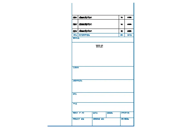
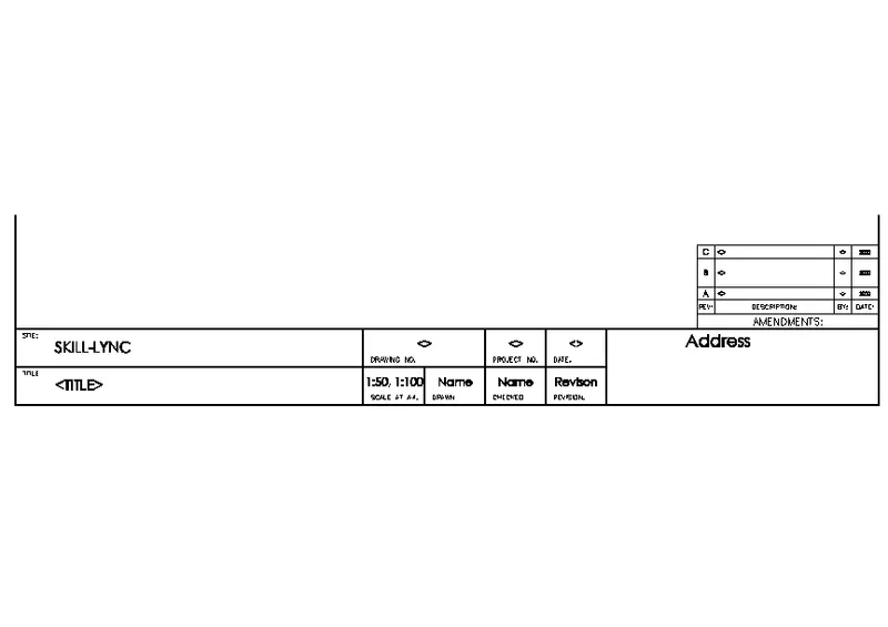
AIM-
TO CREATE THE TEMPLATES AS SHOWN IN FIGURES USING AUTOCAD.
INTRODUCTION -
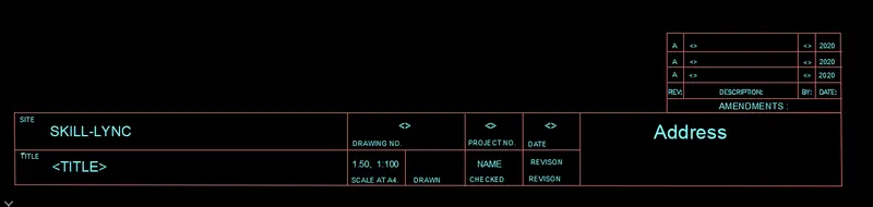
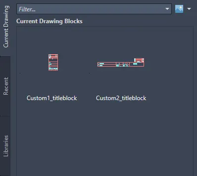
The template is drafted using AutoCAD software as per figures and sizes of the title block are taken as per industry standards and some off the sizes are assume as per the size of the paper. the text and aattributes are used while drafting and after creating the title block save it as a block with names : Custom1_titleblock , Custom2_titleblock
The comand used for making the drawing is given below as well as all the step are mention with pictures which is drafted and taken from AutoCAD
TOOLS USED-
- LINE - Command for line is L
- CONSTRUCTTION LINE - Command for construction line is XL
- TRIM - Command for trim is TR
- TEXT- Command for text is DTEXT/MTEXT
- DIMENSION - Command for line is Dimension DIM
- OFFSET - Command for offset is O
- FILLET - Command for fillet is F
- LAYERS -Command for layer is LA
- CIRCLE - Command for circle is C
- RECTANGLE - Command for the rectangle is REC
- TABLE - command for table is table
- BLOCK - command for block is B
- ATTRIBUTE - command for attribute is ATT
- INSERT - command for insert is I
- FIELD - command for field is feild
PROCEDURE-
STEP 1
- Go to START MENU, and select AutoCAD.
- The User Interface of AutoCAD is OPEN.
- Click the start Drawing tab
- The workspace of AutoCad is open,
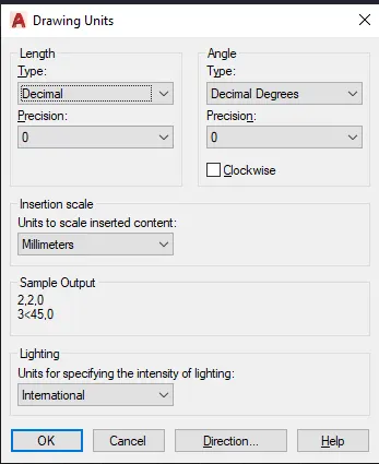
- Enter UNITS in the command box.
- Select DECIMAL in TYPE, 0 in PRECISION, and MILLIMETER in UNITS TO SCALE INSERTED CONTENT.
- Select Angle type as DECIMAL DEGREE, and precision is 0 and direction are Anti-clockwise.
- Press OK.
STEP 2
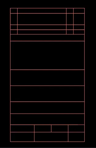
- Select a table command from the ribbion or type TABLE and press ENTER
- Select a no of column and no of row as per the figure and Specify the height and width to them and press OK.
- Select the trim command from the ribbion in modify tab or type TR and press ENTER in the command line
- and trim the unwanted lines
STEP 3
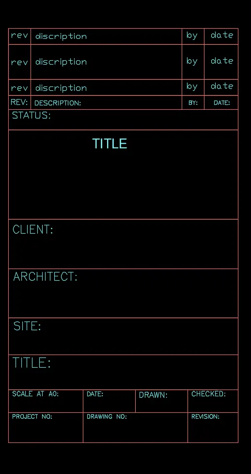
- Select the multiline text from the ribbion HOME > ANNOTATE >TEXT > MUTILINE TEXT
- or type MTEXT and press ENTER in the command line
- and write the text as per the figure
- Select a copy tool from the ribbion in modify tab or type CO nad press ENTER in the command line
- Copy the text and place no. of time required as per the figures
- Now type ED for edit the text and change the name
STEP 4
- After complete of the template
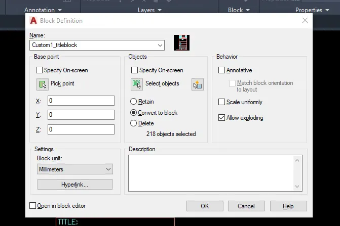
- Select the template and type B and press ENTER a dialog box will open
- in name write Custom1_titleeeblock as given in the task
- PRESS OK.
STEP 5
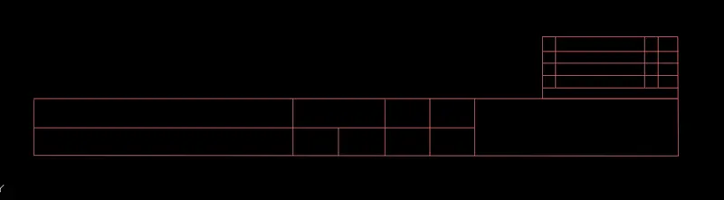
- Select a table command from the ribbion or type TABLE and press ENTER
- Select a no of column and no of row as per the figure and Specify the height and width to them and press OK.
- Select the trim command from the ribbion in modify tab or type TR and press ENTER in the command line
- and trim the unwanted lines
STEP 6
- Select the multiline text from the ribbion HOME > ANNOTATE >TEXT > MUTILINE TEXT
- or type MTEXT and press ENTER in the command line
- and write the text as per the figure
- Select a copy tool from the ribbion in modify tab or type CO nad press ENTER in the command line
- Copy the text and place no. of time required as per the figures
- Now type ED for edit the text and change the name
STEP 7
- After complete of the template
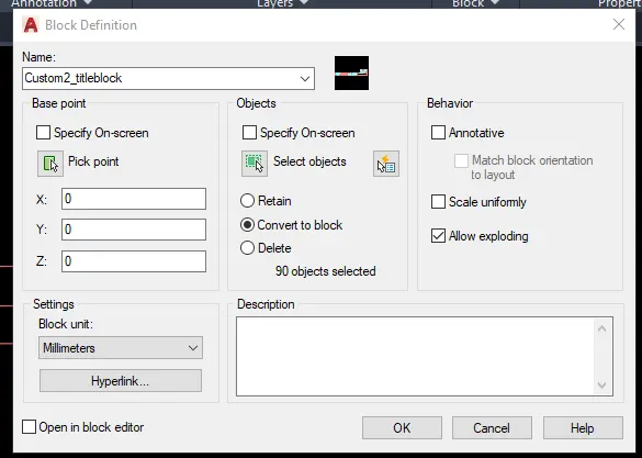
- Select the template and type B and press ENTER a dialog box will open
- in name write Custom2_titleeeblock as given in the task
- PRESS OK.
RESULT-
2. DOORS
AIM-
TO CREATE THE DOOR AS SHOWN IN FIGURES USING AUTOCAD.
INTRODUCTION -
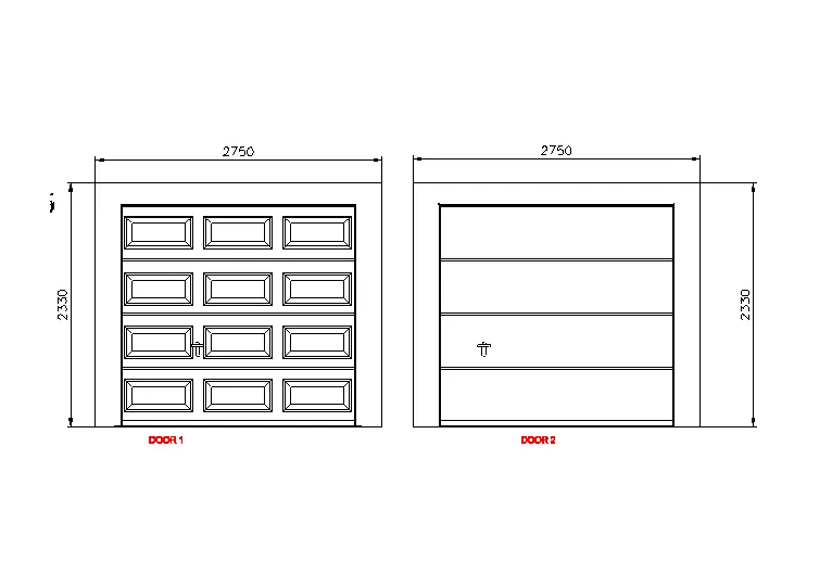
The Doors elevation is drafted using AutoCAD software as per figures and need to create each door type as per standered size or given dimensions and create the block of this door type after creating the.
The comand used for making the drawing is given below as well as all the step are mention with pictures which is drafted and taken from AutoCAD
TOOLS USED-
- LINE - Command for line is L
- CONSTRUCTTION LINE - Command for construction line is XL
- TRIM - Command for trim is TR
- TEXT- Command for text is DTEXT/MTEXT
- DIMENSION - Command for line is Dimension DIM
- OFFSET - Command for offset is O
- FILLET - Command for fillet is F
- LAYERS -Command for layer is LA
- CIRCLE - Command for circle is C
- RECTANGLE - Command for the rectangle is REC
- TABLE - command for table is table
- BLOCK - command for block is B
- ATTRIBUTE - command for attribute is ATT
- INSERT - command for insert is I
- FIELD - command for field is feild
PROCEDURE-
STEP 1
- Go to START MENU, and select AutoCAD.
- The User Interface of AutoCAD is OPEN.
- Click the start Drawing tab
- The workspace of AutoCad is open,
- Enter UNITS in the command box.
- Select DECIMAL in TYPE, 0 in PRECISION, and MILLIMETER in UNITS TO SCALE INSERTED CONTENT.
- Select Angle type as DECIMAL DEGREE, and precision is 0 and direction are Anti-clockwise.
- Press OK.
STEP 2
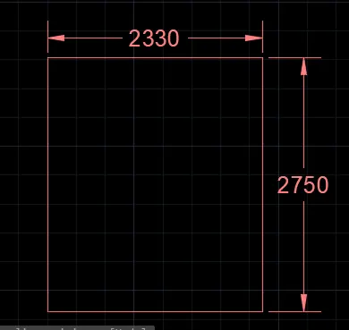
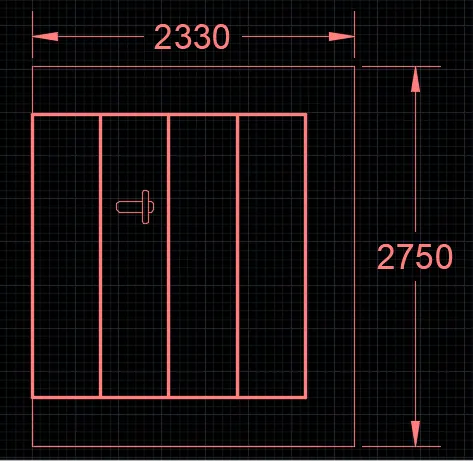
- Select the rectangle tool from the ribbion in draw menu or type REC and press ENTER
- Click on the dimension in the commmand line
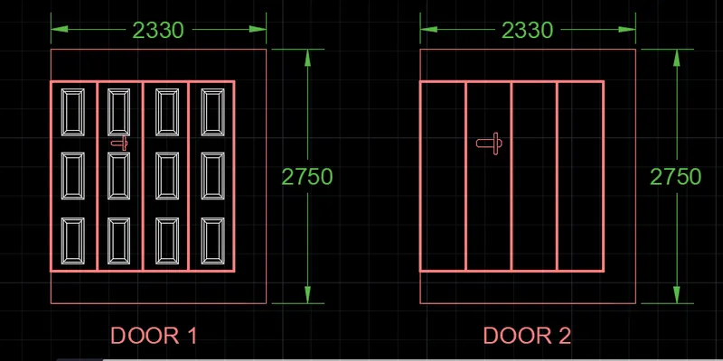
- Specify the length pf rectangle as 2330
- and width od rectangle as 2750 and lick on the screen
- press ESC
STEP 3
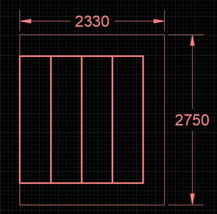
- Type X ENTER to explode the rectangle
- Select the OFFSET tool from the ribbon in MODIFY menu or type O and press ENTER
- Specify offset distance and slect all the 3 sides of the rectangle
- press ESC
STEP 4
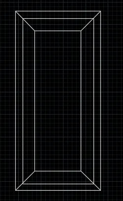
- Creating a window panel using the line tool and offset tool
STEP 5
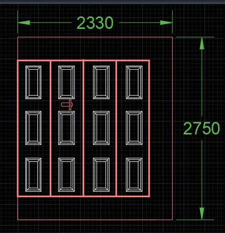
- place the window pannel at all the desired location as shown.
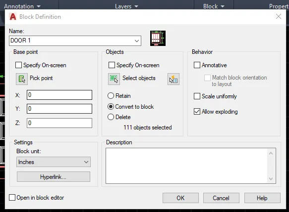
STEP 6
- After complete of the door drafting
- Select the template and type B and press ENTER a dialog box will open
- in name write DOOR1 as given in the task
- PRESS OK
STEP 7
- Select the rectangle tool from the ribbion in draw menu or type REC and press ENTER
- Click on the dimension in the commmand line
- Specify the length pf rectangle as 2330
- and width od rectangle as 2750 and lick on the screen
- press ESC
STEP 8
- Type X ENTER to explode the rectangle
- Select the OFFSET tool from the ribbon in MODIFY menu or type O and press ENTER
- Specify offset distance and slect all the 3 sides of the rectangle
- press ESC
STEP 9
- Creat a door handle using line and fillet tool
STEP 10
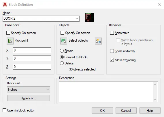
- After complete of the door drafting
- Select the template and type B and press ENTER a dialog box will open
- in name write DOOR2 as given in the task
- PRESS OK
RESULT -
3. SYMBOL LEGEND
AIM-
TO CREATE THE SYMBOLS AS SHOWN IN FIGURES USING AUTOCAD.
INTRODUCTION -
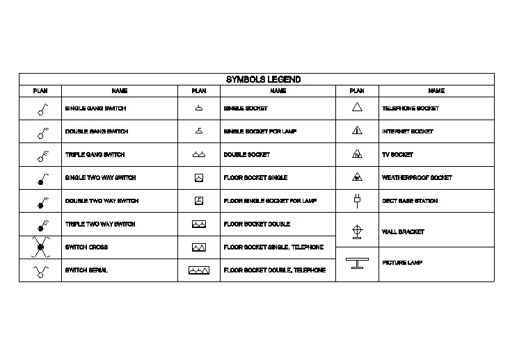
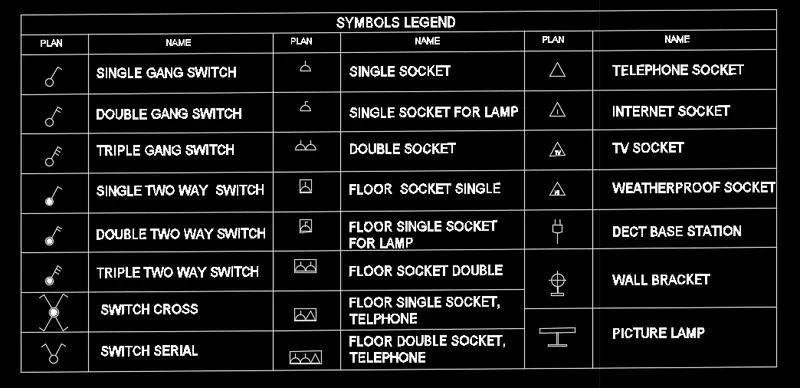
The symbol is drafted using AutoCAD software as per figures and sizes later each symbol is created as a block with a name given in the legend, after creating the block arrange them in legend as shown
The comand used for making the drawing is given below as well as all the step are mention with pictures which is drafted and taken from AutoCAD
TOOLS USED-
- LINE - Command for line is L
- CONSTRUCTTION LINE - Command for construction line is XL
- TRIM - Command for trim is TR
- TEXT- Command for text is DTEXT/MTEXT
- DIMENSION - Command for line is Dimension DIM
- OFFSET - Command for offset is O
- FILLET - Command for fillet is F
- LAYERS -Command for layer is LA
- CIRCLE - Command for circle is C
- RECTANGLE - Command for the rectangle is REC
- TABLE - command for table is table
- BLOCK - command for block is B
- ATTRIBUTE - command for attribute is ATT
- INSERT - command for insert is I
- FIELD - command for field is feild
PROCEDURE-
STEP 1
- Go to START MENU, and select AutoCAD.
- The User Interface of AutoCAD is OPEN.
- Click the start Drawing tab
- The workspace of AutoCad is open,
- Enter UNITS in the command box.
- Select DECIMAL in TYPE, 0 in PRECISION, and MILLIMETER in UNITS TO SCALE INSERTED CONTENT.
- Select Angle type as DECIMAL DEGREE, and precision is 0 and direction are Anti-clockwise.
- Press OK.
STEP 2
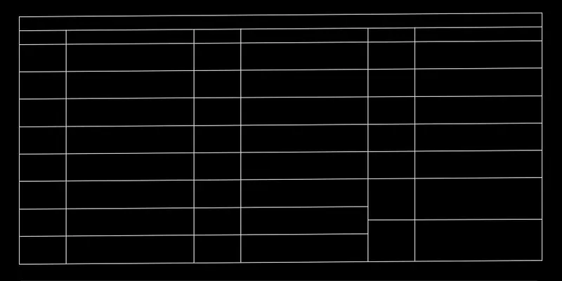
- Select a table command from the ribbion or type TABLE and press ENTER
- Select a no of column and no of row as per the figure and Specify the height and width to them and press OK.
- Select the trim command from the ribbion in modify tab or type TR and press ENTER in the command line
- and trim the unwanted lines
STEP 3
- Draw all the symbol and make the seprate block of each one

STEP 4
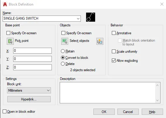
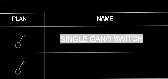
- Give thee name of block as shown in images as the name of foirst block is SINGLE GANG SWITCH
STEP 5
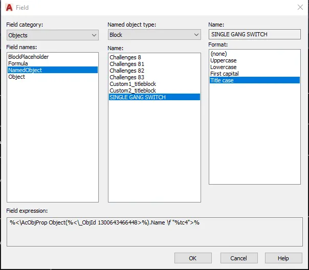
- Go to the Field by command field in the command line
- Select Field category as object
- Field name as Namedobject
- Select object type as a block
- Select the block name
- press OK.
STEP 6
- PLACE IT AT THE TABLE THAT CREATED IN STEP 2
RESULT -
4. DOORS ELEVATION
AIM-
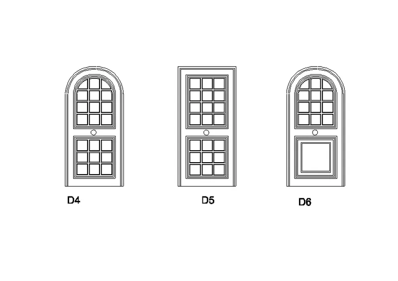
TO CREATE THE DOOR ELEVATION AS SHOWN IN FIGURES USING AUTOCAD.
INTRODUCTION -
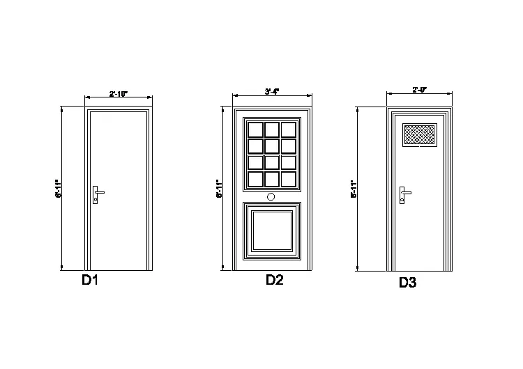
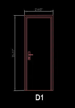
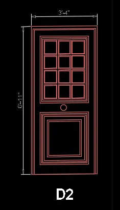
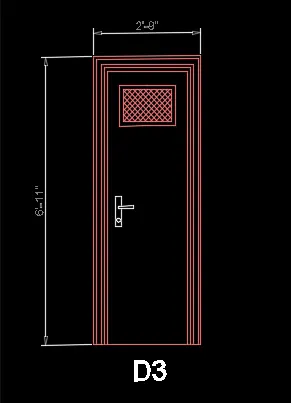
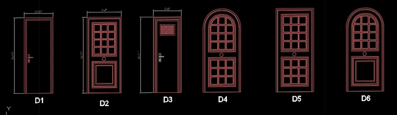
The door elevation is drafted using AutoCAD software as per figures and each door is created as a block some dimesions are given in the project and some are assumed as per industry standard.
The comand used for making the drawing is given below as well as all the step are mention with pictures which is drafted and taken from AutoCAD
TOOLS USED-
- LINE - Command for line is L
- CONSTRUCTTION LINE - Command for construction line is XL
- TRIM - Command for trim is TR
- TEXT- Command for text is DTEXT/MTEXT
- DIMENSION - Command for line is Dimension DIM
- OFFSET - Command for offset is O
- FILLET - Command for fillet is F
- LAYERS -Command for layer is LA
- CIRCLE - Command for circle is C
- RECTANGLE - Command for the rectangle is REC
- TABLE - command for table is table
- BLOCK - command for block is B
- ATTRIBUTE - command for attribute is ATT
- INSERT - command for insert is I
- FIELD - command for field is feild
PROCEDURE-
STEP 1
- Go to START MENU, and select AutoCAD.
- The User Interface of AutoCAD is OPEN.
- Click the start Drawing tab
- The workspace of AutoCad is open,
- Enter UNITS in the command box.
- Select DECIMAL in TYPE, 0 in PRECISION, and MILLIMETER in UNITS TO SCALE INSERTED CONTENT.
- Select Angle type as DECIMAL DEGREE, and precision is 0 and direction are Anti-clockwise.
- Press OK.
STEP 2
- Creating of DOOR 1 using drating tool like line rectangle and offset and later dimension are mention
STEP 3
- Creating of DOOR 2 using drating tool like line rectangle and offset and later dimension are mention
STEP 4
- Creating of DOOR 3 using drating tool like line rectangle and offset and later dimension are mention
STEP 5
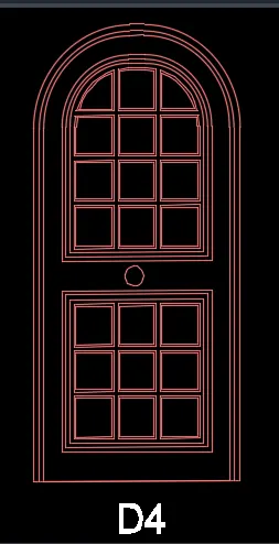
- Creating of DOOR 4 using drating tool like line rectanglel and offset and later dimension are mention
STEP 6
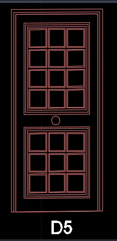
- Creating of DOOR 5 using drating tool like line rectangle and offset and later dimension are mention
STEP 7
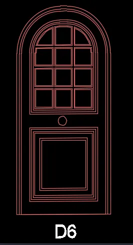
- Creating of DOOR 6 using drating tool like line rectangle and offset and later dimension are mention
RESULT -
5. ELECTRIC SYMBOLS
AIM-
TO CREATE THE ELECTRIC SYMBOL AS SHOWN IN FIGURES USING AUTOCAD.
INTRODUCTION -
The electric symbol legend is drafted using AutoCAD software as per figures and after drafting process each symbol is created as block and save the block and insert it in the table
The comand used for making the drawing is given below as well as all the step are mention with pictures which is drafted and taken from AutoCAD
TOOLS USED-
- LINE - Command for line is L
- CONSTRUCTTION LINE - Command for construction line is XL
- TRIM - Command for trim is TR
- TEXT- Command for text is DTEXT/MTEXT
- DIMENSION - Command for line is Dimension DIM
- OFFSET - Command for offset is O
- FILLET - Command for fillet is F
- LAYERS -Command for layer is LA
- CIRCLE - Command for circle is C
- RECTANGLE - Command for the rectangle is REC
- TABLE - command for table is table
- BLOCK - command for block is B
- ATTRIBUTE - command for attribute is ATT
- INSERT - command for insert is I
- FIELD - command for field is feild
PROCEDURE-
STEP 1
- Go to START MENU, and select AutoCAD.
- The User Interface of AutoCAD is OPEN.
- Click the start Drawing tab
- The workspace of AutoCad is open,
- Enter UNITS in the command box.
- Select DECIMAL in TYPE, 0 in PRECISION, and MILLIMETER in UNITS TO SCALE INSERTED CONTENT.
- Select Angle type as DECIMAL DEGREE, and precision is 0 and direction are Anti-clockwise.
- Press OK.
STEP 2
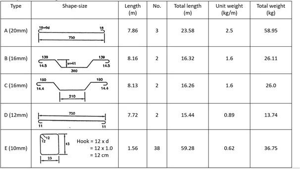
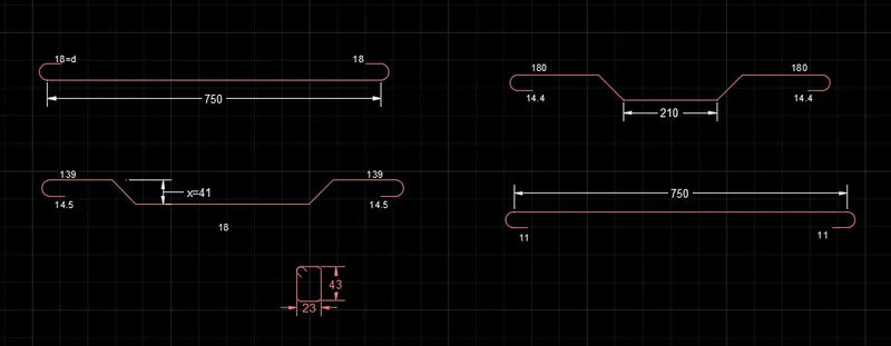
- Making of bar bending diagram as shown iin picture
STEP 3
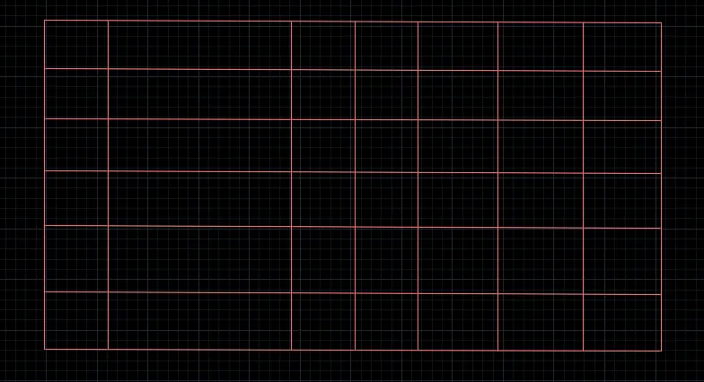
- Select a table command from the ribbion or type TABLE and press ENTER
- Select a no of column and no of row as per the figure and Specify the height and width to them and press OK.
- Select the trim command from the ribbion in modify tab or type TR and press ENTER in the command line
- and trim the unwanted lines
STEP 4
- Select the multiline text from the ribbion HOME > ANNOTATE >TEXT > MUTILINE TEXT
- or type MTEXT and press ENTER in the command line
- and write the text as per the figure
- Select a copy tool from the ribbion in modify tab or type CO nad press ENTER in the command line
- Copy the text and place no. of time required as per the figures
- Now type ED for edit the text and change the name
RESULT-