Creating Bar Bending schedule, Different Door types, and Creation of standard drawing templates using AutoCad
1)
Aim:
Create the title block 1 for required dimentions
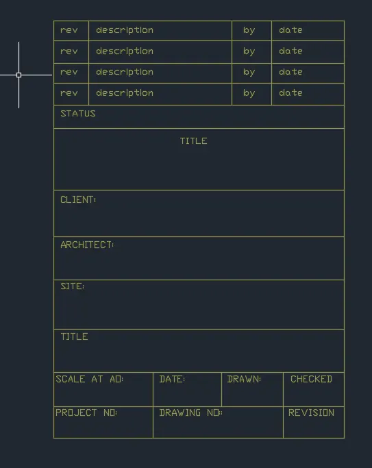
- In command prompt type (startup:1)
- Then file>new
- Then create new drawing window select metric in default settings
- In advanced setup in units check on the decimal, angle in degrees, then ok
- In command prompt type (xl enter h enter v) construction line horizontal and vertical respectively is obtained
- Next, in command prompt type (o and specify distance of offset as 600) and offset the horizontal line to top
- Next, in command prompt type (o and specify distance of offset as 600) and offset the horizontal line to top
- Next, in command prompt type (o and specify distance of offset as 900) and offset the horizontal line to top
- Next, in command prompt type (o and specify distance of offset as 900) and offset the horizontal line to top
- Next, in command prompt type (o and specify distance of offset as 900) and offset the horizontal line to top
- Next, in command prompt type (o and specify distance of offset as 900) and offset the horizontal line to top
- Next, in command prompt type (o and specify distance of offset as 1200) and offset the horizontal line to top
- Next, in command prompt type (o and specify distance of offset as 300) and offset the horizontal line to top
- Next, in command prompt type (o and specify distance of offset as 300) and offset the horizontal line to top
- Next, in command prompt type (o and specify distance of offset as 300) and offset the horizontal line to top
- Next, in command prompt type (o and specify distance of offset as 300) and offset the horizontal line to top
- Next, in command prompt type (o and specify distance of offset as 300) and offset the horizontal line to top
- Next, in command prompt type (o and specify distance of offset as 500) and offset the vertical line to right
- Next, in command prompt type (o and specify distance of offset as 2500) and offset the vertical line to right
- Next, in command prompt type (o and specify distance of offset as 500) and offset the vertical line to right
- Next, in command prompt type (o and specify distance of offset as 1000) and offset the vertical line to right
- Now, trim and fillet all the required lines
- In command prompt type (at) and define the attribute and tag, prompt and default for date assign its position
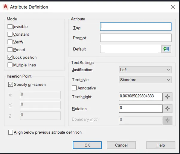
- Similarly continue this process for all the attributes and assign to is position (e.g., drawn, title, checked, scale, rev, description)
- In command prompt type (b) and define the block by selecting the base point and the selecting the objects
- Now block of the title block 1 is created
- With the help of the scale tool we can scale the block for the required size with the scale reference.
Result:
Title block 1 was created in the AutoCAD drawing
2)
Aim:
Create the title block 2 for required dimentions
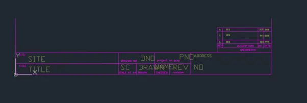
- In command prompt type (startup:1)
- Then file>new
- Then create new drawing window select metric in default settings
- In advanced setup in units check on the decimal, angle in degrees, then ok
- In command prompt type (xl enter h enter v) construction line horizontal and vertical respectively is obtained
- Next, in command prompt type (o and specify distance of offset as 1000) and offset the horizontal line to top
- Next, in command prompt type (o and specify distance of offset as 1000) and offset the horizontal line to top
- Next, in command prompt type (o and specify distance of offset as 300) and offset the horizontal line to top
- Next, in command prompt type (o and specify distance of offset as 300) and offset the horizontal line to top
- Next, in command prompt type (o and specify distance of offset as 300) and offset the horizontal line to top
- Next, in command prompt type (o and specify distance of offset as 600) and offset the horizontal line to top
- Next, in command prompt type (o and specify distance of offset as 300) and offset the horizontal line to top
- Next, in command prompt type (o and specify distance of offset as 8000) and offset the vertical line to right
- Next, in command prompt type (o and specify distance of offset as 1000) and offset the vertical line to right
- Next, in command prompt type (o and specify distance of offset as 1000) and offset the vertical line to right
- Next, in command prompt type (o and specify distance of offset as 1000) and offset the vertical line to right
- Next, in command prompt type (o and specify distance of offset as 1000) and offset the vertical line to right
- Next, in command prompt type (o and specify distance of offset as 6000) and offset the vertical line to right
- Trim all the unwanted lines.
- In command prompt type (at) and define the attribute and tag, prompt and default for date assign its position
- Similarly continue this process for all the attributes and assign to is position (e.g., drawn, title, checked, scale, rev, description)
- With the help of the dtext provide the headings for the rows
- In command prompt type (b) and define the block by selecting the base point and the selecting the objects
- Now block of the title block 2 is created
- With the help of the scale tool we can scale the block for the required size with the scale reference.
Result:
Title block 2 was created in the AutoCAD drawing
3)
Aim:
Sketch the doors in AutoCAD
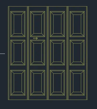
- In command prompt type (startup:1)
- Then file>new
- Then create new drawing window select metric in default settings
- In advanced setup in units check on the decimal, angle in degrees, then ok
- In command prompt type (xl enter h enter v) construction line horizontal and vertical respectively is obtained
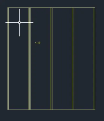
- Next, in command prompt type (o and specify distance of offset as 2400) and offset the horizontal line to top
- Next, in command prompt type (o and specify distance of offset as 50) and offset the horizontal line to top
- Next, in command prompt type (o and specify distance of offset as 50) and offset the horizontal top line to bottom
- Next, in command prompt type (o and specify distance of offset as 50) and offset the vertical line to right
- Next, in command prompt type (o and specify distance of offset as 600) and offset the vertical line to right
- Next, in command prompt type (o and specify distance of offset as 50) and offset the vertical line to left
- Trim all unwanted lines
- With rectangle tool and snapping option draw the rectangle at centre 400*600
- Now offset 25 inwards rectangle and also again offset 75 Inwards and join all the corners of the rectangle
- Copy the rectangle and place it above and bottom portion of the door
- Select all the objects and copy 4 times to the right
- And draw the bolt using line command and trim and fillet command
- In command prompt type (b) and define the block by selecting the base point and the selecting the objects
- Now block of the door with panels is created
- In command prompt type (startup:1)
- Then file>new
- Then create new drawing window select metric in default settings
- In advanced setup in units check on the decimal, angle in degrees, then ok
- In command prompt type (xl enter h enter v) construction line horizontal and vertical respectively is obtained
- Next, in command prompt type (o and specify distance of offset as 2400) and offset the horizontal line to top
- Next, in command prompt type (o and specify distance of offset as 50) and offset the horizontal line to top
- Next, in command prompt type (o and specify distance of offset as 50) and offset the horizontal top line to bottom
- Next, in command prompt type (o and specify distance of offset as 50) and offset the vertical line to right
- Next, in command prompt type (o and specify distance of offset as 600) and offset the vertical line to right
- Next, in command prompt type (o and specify distance of offset as 50) and offset the vertical line to left
- Trim all unwanted lines
- Copy the rectangle and place it above and bottom portion of the door
- Select all the objects and copy 4 times to the right
- And draw the bolt using line command and trim and fillet command
- In command prompt type (b) and define the block by selecting the base point and the selecting the objects
- Now block of the door with panels is created
Result:
Plain door and the doors with panel block was done in AutoCAD
4)
Aim:
Sketch each symbol as a block with the name given in the legend. After creating the blocks arrange them in the legend
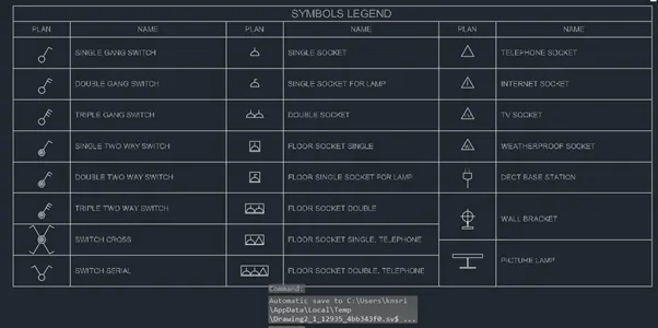
- In the annotation bar open the table
- And specify the required number of the row and columns
- And also specify the row height
- Enter the title as the symbol’s legend and
- Type all the name in the specified rows and
- Justify the text in the table for the left justify
- Now create all the symbols outside the table with the help of the line, circle and rect commands
- With the help of the scale option scale the objects to the required height and copy the symbol created to the respective positions in the table
- Select the text and respective symbol and create all the individual block for every symbol
- Adjust the column sizes of the table as required
- Select whole legend and create the legend block
Result:
each symbol as a block with the name given in the legend. After creating the blocks arrange them in the legend
5)
Aim:
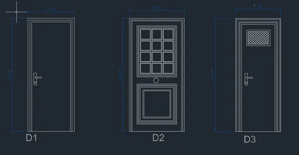
Sketch of the door and creation of blocks
- In command prompt type (startup:1)
- Then file>new
- Then create new drawing window select metric in default settings
- In advanced setup in units check on the decimal, angle in degrees, then ok
- In command prompt type (xl enter h enter v) construction line horizontal and vertical respectively is obtained
- Next, in command prompt type (o and specify distance of offset as 2100) and offset the horizontal line to top
- Next, in command prompt type (o and specify distance of offset as 30) and offset the horizontal line of top to bottom twice
- Next, in command prompt type (o and specify distance of offset as 850) and offset the vertical line to right
- Next, in command prompt type (o and specify distance of offset as 30) and offset the vertical line to left and right of both corner lines inwards
- Trim and fillet all the required lines
- With line command draw the bolt and make it as the block
- Place the bolt in the required position and D1 is created
- Copy the exterior lines of the D1 and place then extend the horizontal lines to 1000
- Create a rectangle of the 730*940 at an offset of the 90 from 100 from top line
- Then offset the rectangle inward for 20 mm 3 times
- In the3 centre point as reference place a rectangle of 190*200
- And offset in inwards for the 10mm
- Copy the rectangle for 20mm on both sides
- Copy 3 rectangle with the spacing of 20mm toward bottom
- Draw a rectangle of the 740*740 at 130mm from above rectangle
- Offset it inward for the 20 mm for 3times and offset it for the 50mm once and again offset it for the 20mm inward
- Copy the exterior lines of the D1 and place
- Offset the exterior line for the 50mm inwards
- Then for the 20mm and for 40 mm inwards
- Offset the last top line created for the 100mm downward
- Create a rectangle of the 290*380 and offset of the 30 inwards
- Insert the bolt block and place on screen
- Hatch the interior rectangle and scale it to the required dimension
- D3 is created
- Copy the whole D2
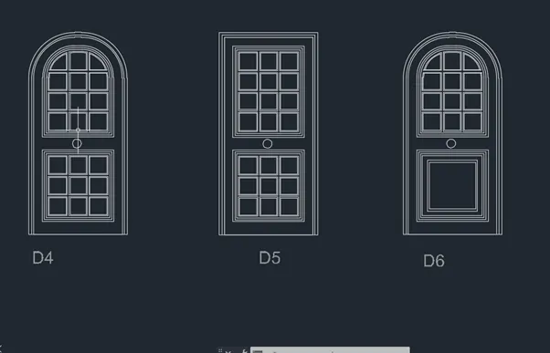
- Offset the bottom line to 1698 for the top
- With this line as the reference trim the above line and delete other and created line
- With arc command draw the arc start end direction by 2 end points as the reference
- Now offset the arc for 30,20,100,20,20,20
- With the trim command delete all the unwanted lines
- Copy 3 rows of the rectangles and place them inside the below rectangle
- Door4 is created
- Copy the door 2 and trim the bottom portion
- And from door 4 copy the bottm portion and place in the door 5
- Therefore door 5 is created
- Copy the door 4 and trim the bottom portion
- And from door 2 copy the bottm portion and place in the door 5
- Therefore door 6 is created
Result:
All doors were created in the AutoCAD drawings
6)
Aim:
Create each shape as a block. Save the block and insert them on the table
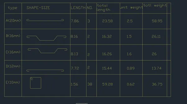
- In the annotation bar open the table
- And specify the required number of the row and columns
- And also specify the row height
- Enter the title as the symbol’s legend and
- Type all the name in the specified rows and
- Justify the text in the table for the left justify
- Now create all the symbols outside the table with the help of the line, circle and rect commands
- With the help of the scale option scale the objects to the required height and copy the symbol created to the respective positions in the table
- Select the text and respective symbol and create all the individual block for every symbol
- Adjust the column sizes of the table as required
- Select whole legend and create the legend block
Result:
each shape as a block was created and Saved the block and inserted them on the table