Creating Architectural and Structural model with 3D rendering using REVIT
1
the type of structure i want to build is School
2
Aim:
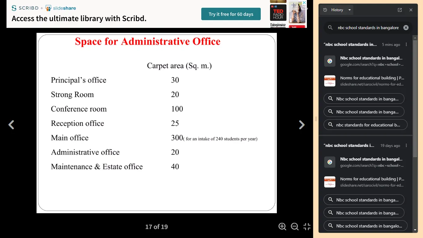
Reasonable assumptions for geographic and location details for project modeling. Based on assumptions and type of structure selected identify the modeling requirements from NBC
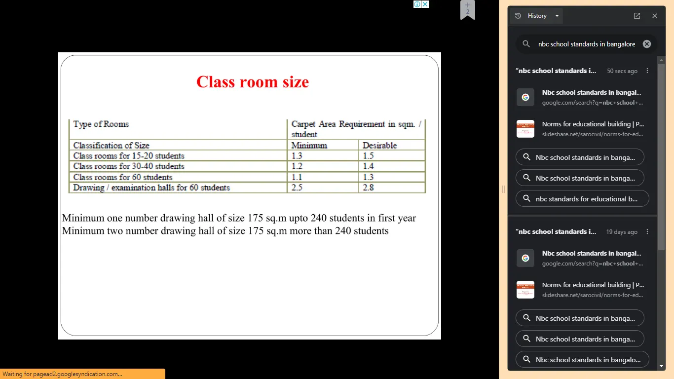
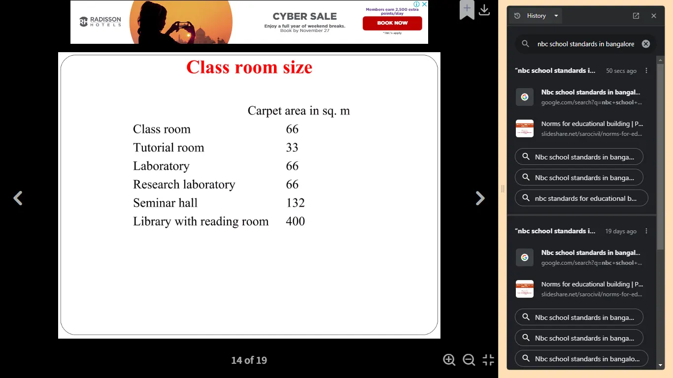
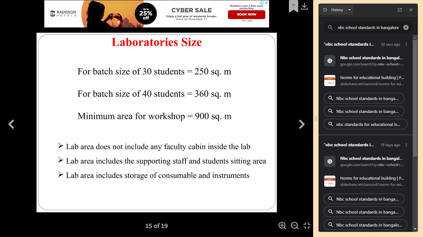
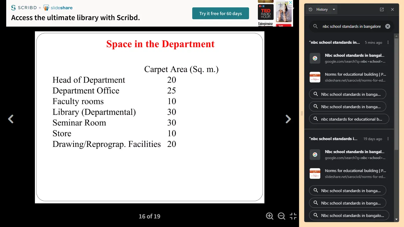
- according to NBC in banglore, a school building constructed in a spacious space, where it is designed considering good amenites, favorable environment, saftey and hygiene of students
- larger class rooms where min of 60 students can easily sit comfortabaly, a laboraorty enough to place all equipments, office room, parents longue, more than one washrrom for both boys and girls and extra for staff, large space for corrider and staircase, library, a big auditorium, play ground and many are planned while designing
- a good drainage or sewage system is provided , during masoon water can easily pass in sewers without logging
- a school should be built in such a way that outside noise is completely avided inside, large parking lots are provided for students, staff and parents, for saftey large compounds are raised along the boundary, road is provided so that vehicle can easily move inside the campus premises
- wall of min 12 feet and min class room area of 600 sqare feet along spacious corridor and stair width is provided
- a large number of windows and ventiliters are provided for easy circulation of air and good light
- in case of saftey a fire hydrants and passage way is provided to come out easily during emergencies
- plants and trees are planted along the campus to keep it cool and refresing. A school environment should be more attractive of optimistic ideas and hygenic
- keeping all this in mind a designer must design a school building prior construction and its opinion should be taken from teachers and managments
- more possible ways a shcool must be energy efficient, only possible by providing good sun light and air naturally. Building must be built considering all of this factors
3
Aim:
Using the structural model, include the following components based on the type of structure selected
a. Foundation – Isolated / Wall/Matt Foundation
b. Columns
c. Beams Connected to Columns
d. Roof Framing/ Truss
e. Floor / Decks
f. Floor Openings for Elevators and Stairs
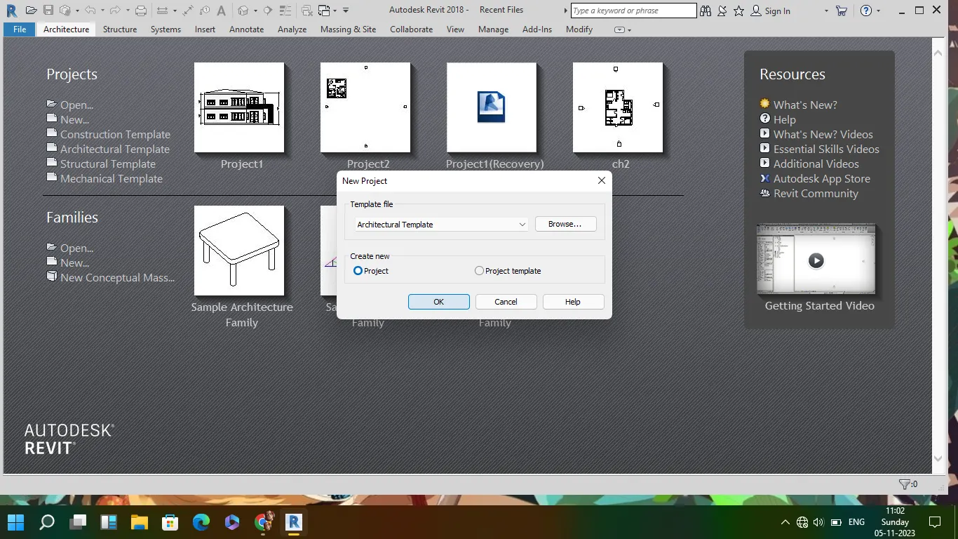
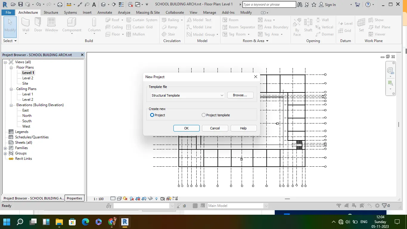
opening of new architecture template
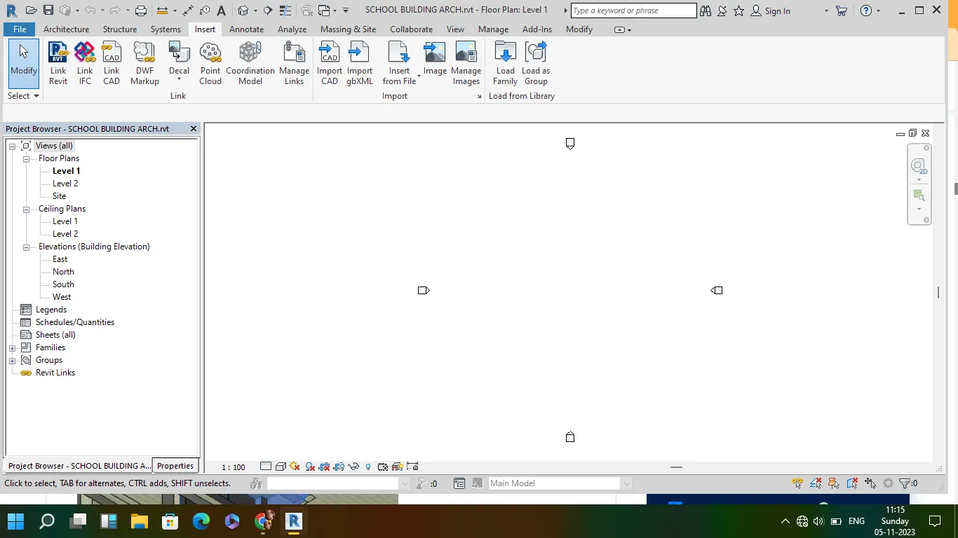
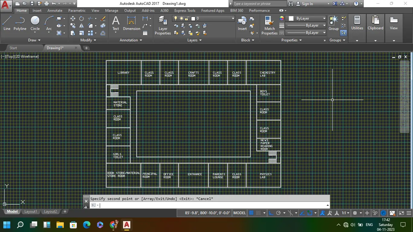
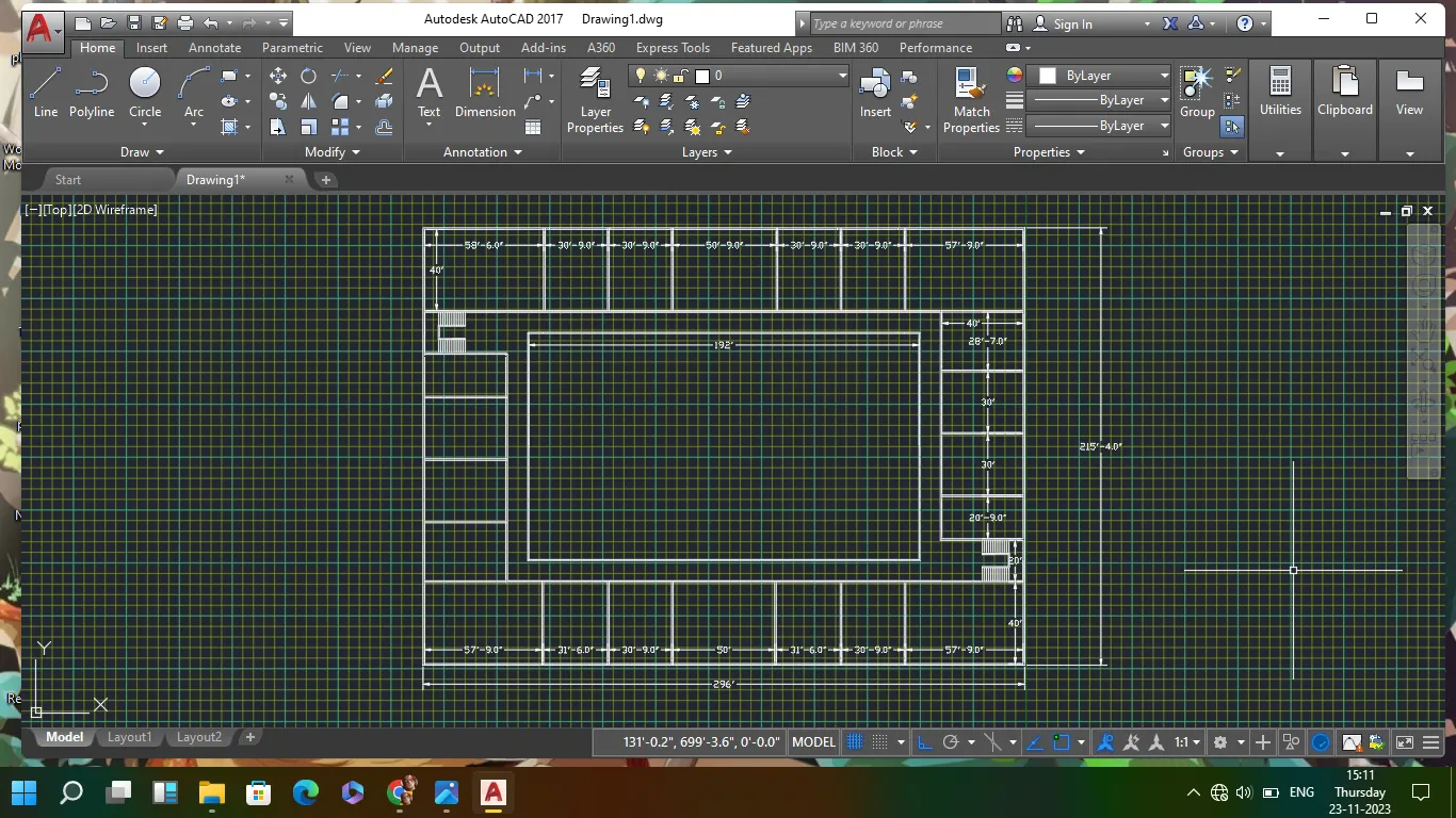
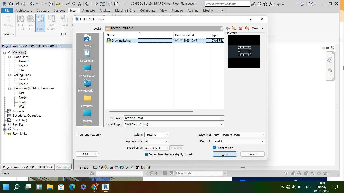
linking the CAD drawing in to revit
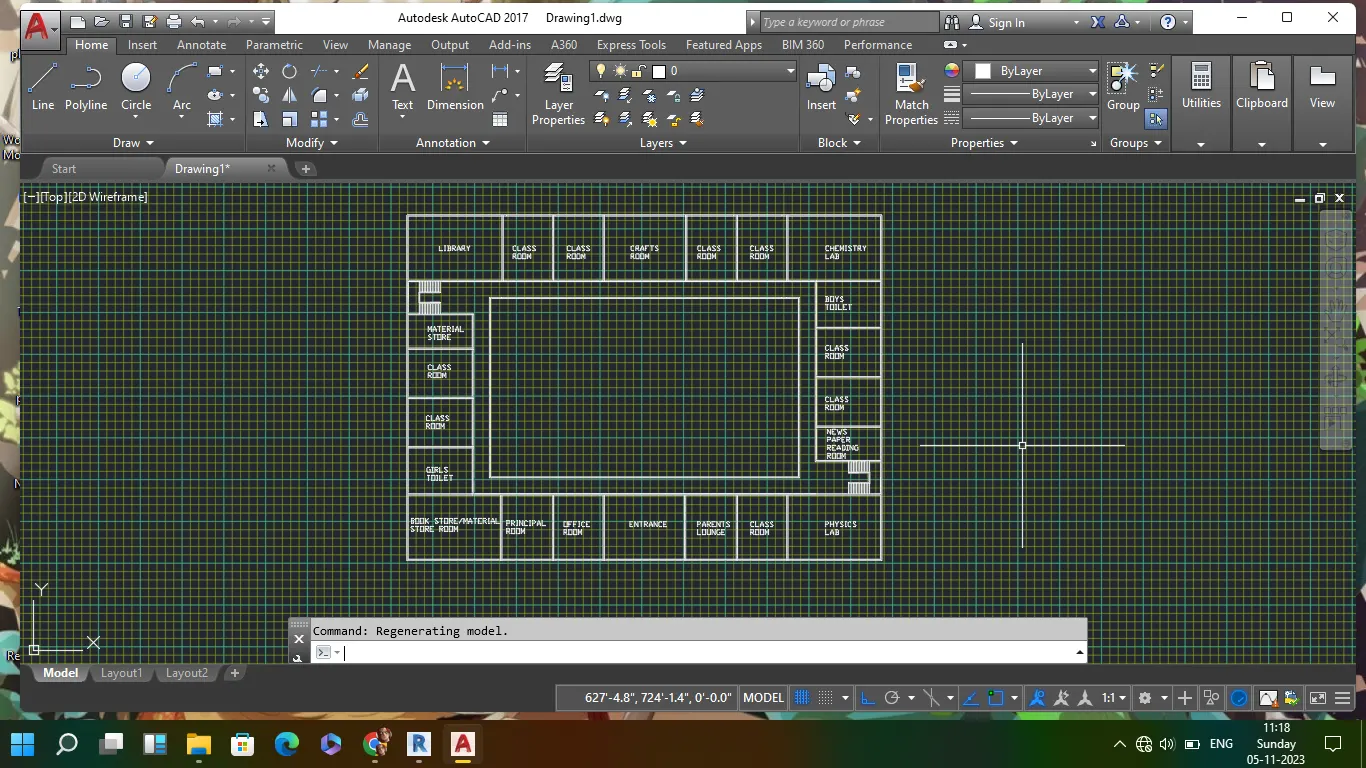
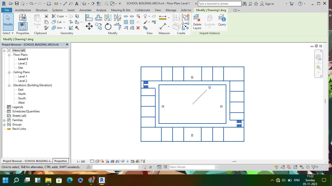
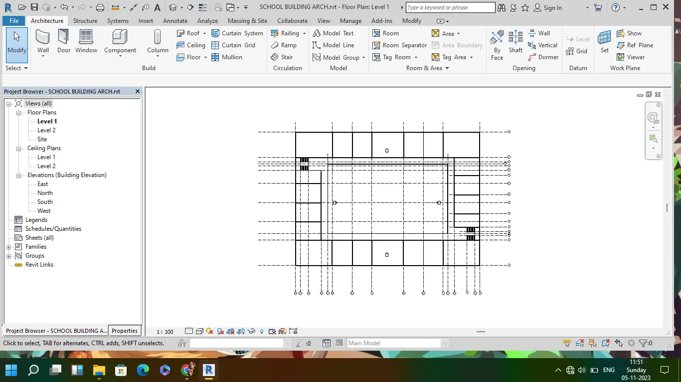
Adding the grid to necessary parts of the drawing, easy reference to add the structural elements
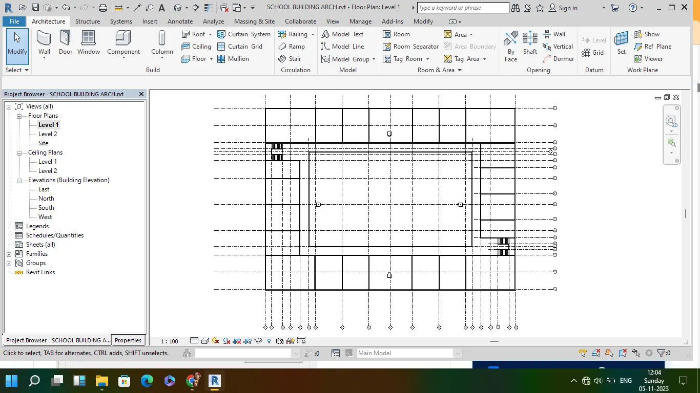
opening new structural template
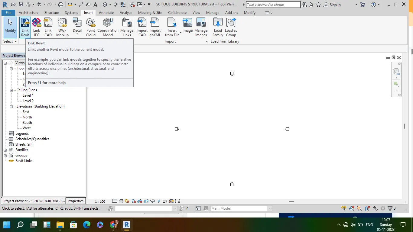
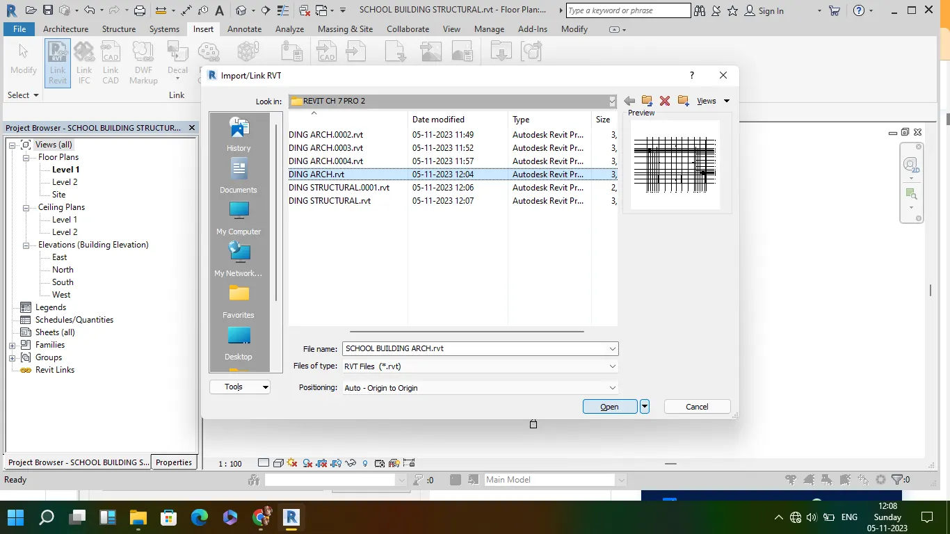
linking the revit file, arch template file into structural template file
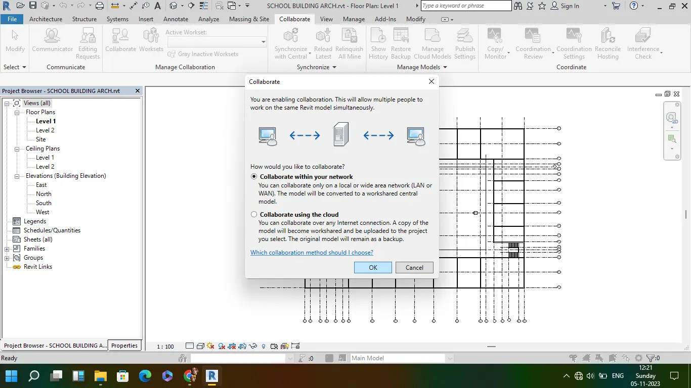
collaborate the revit file with in the network
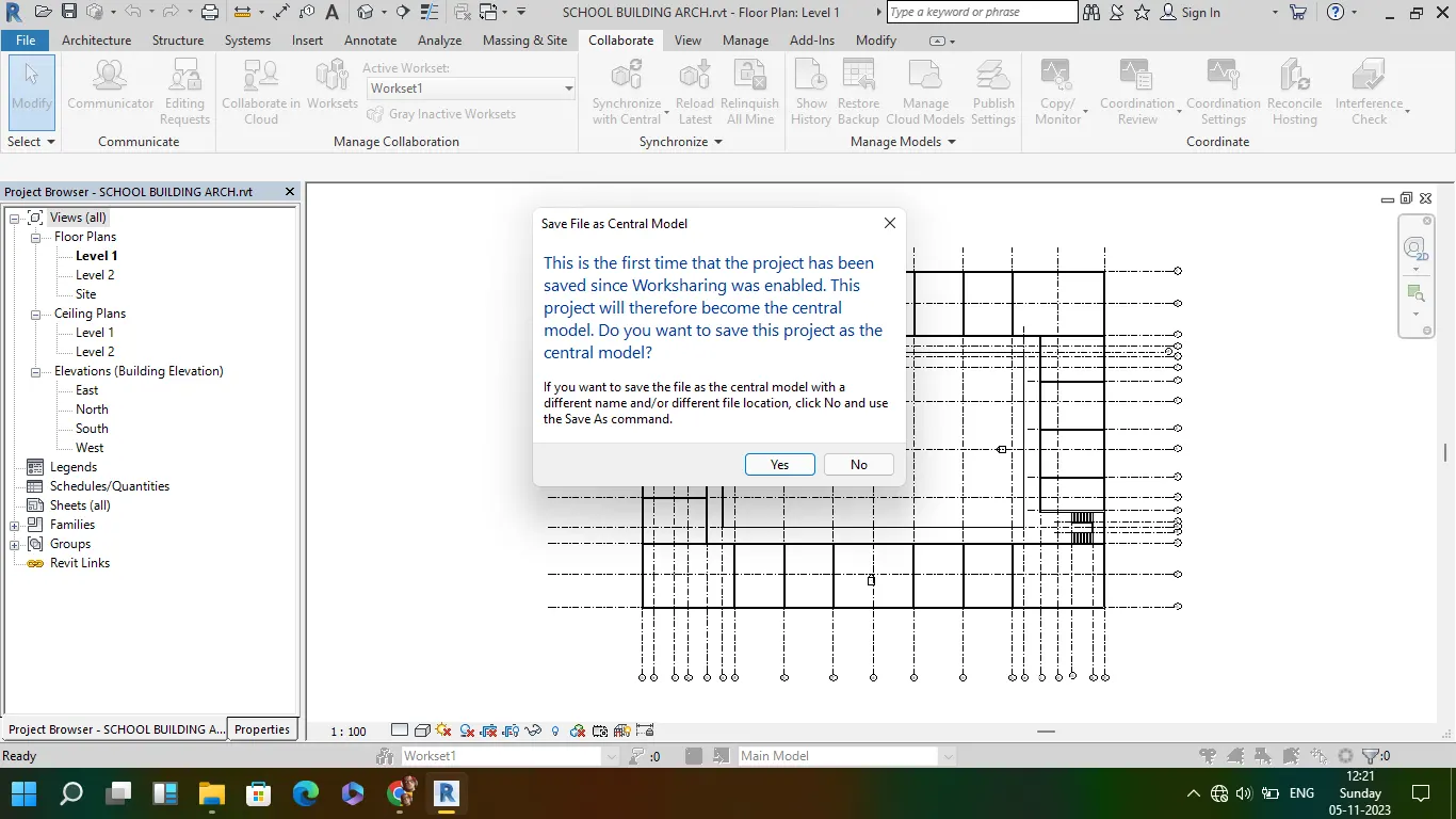
save the file as the central model
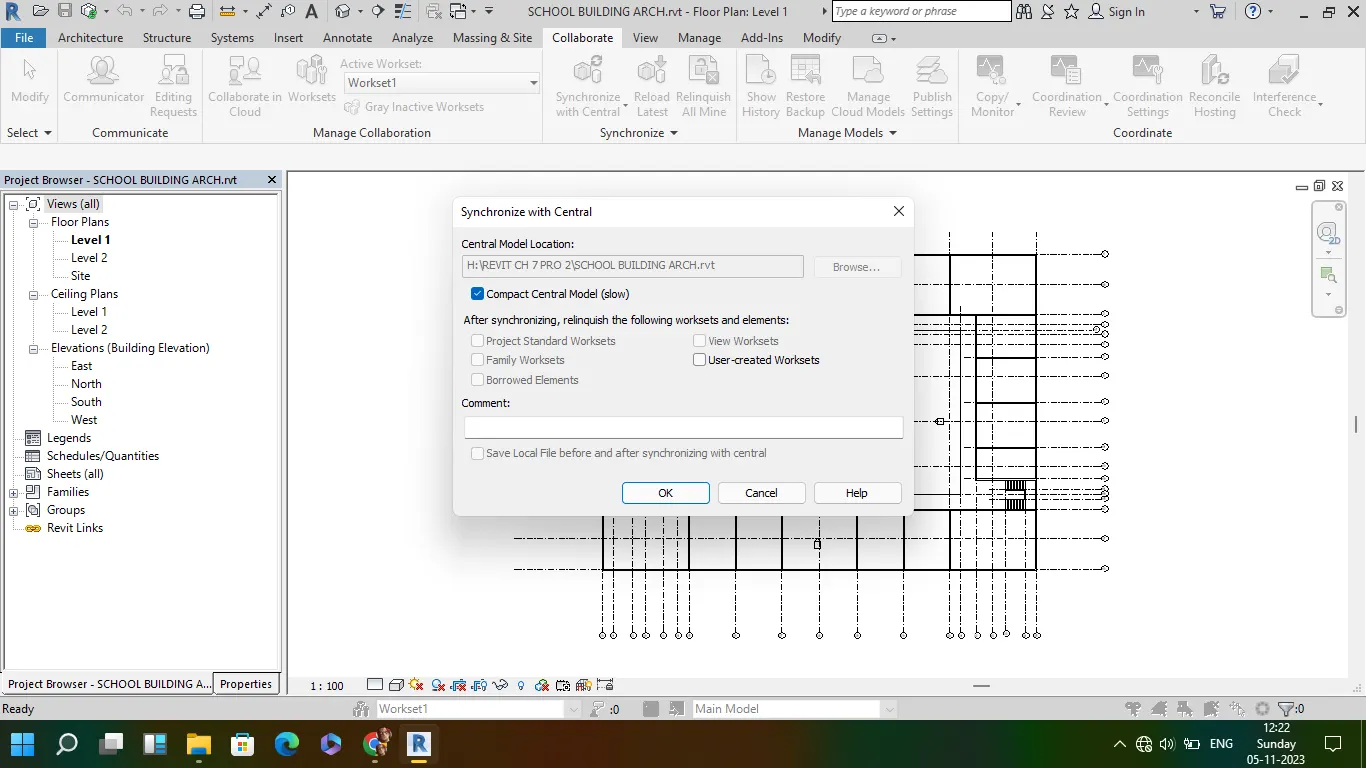
synchronize with central model and copy moniter link arch model in to structural model
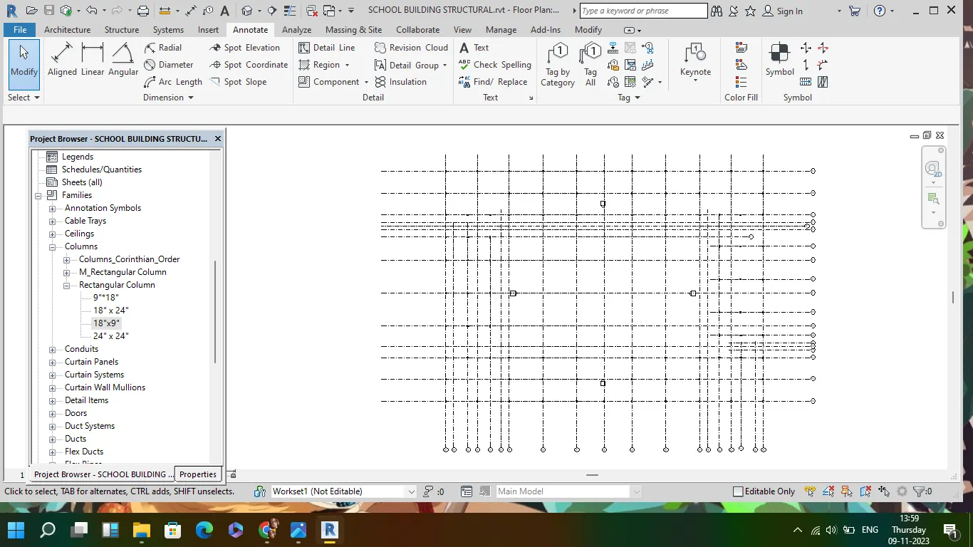
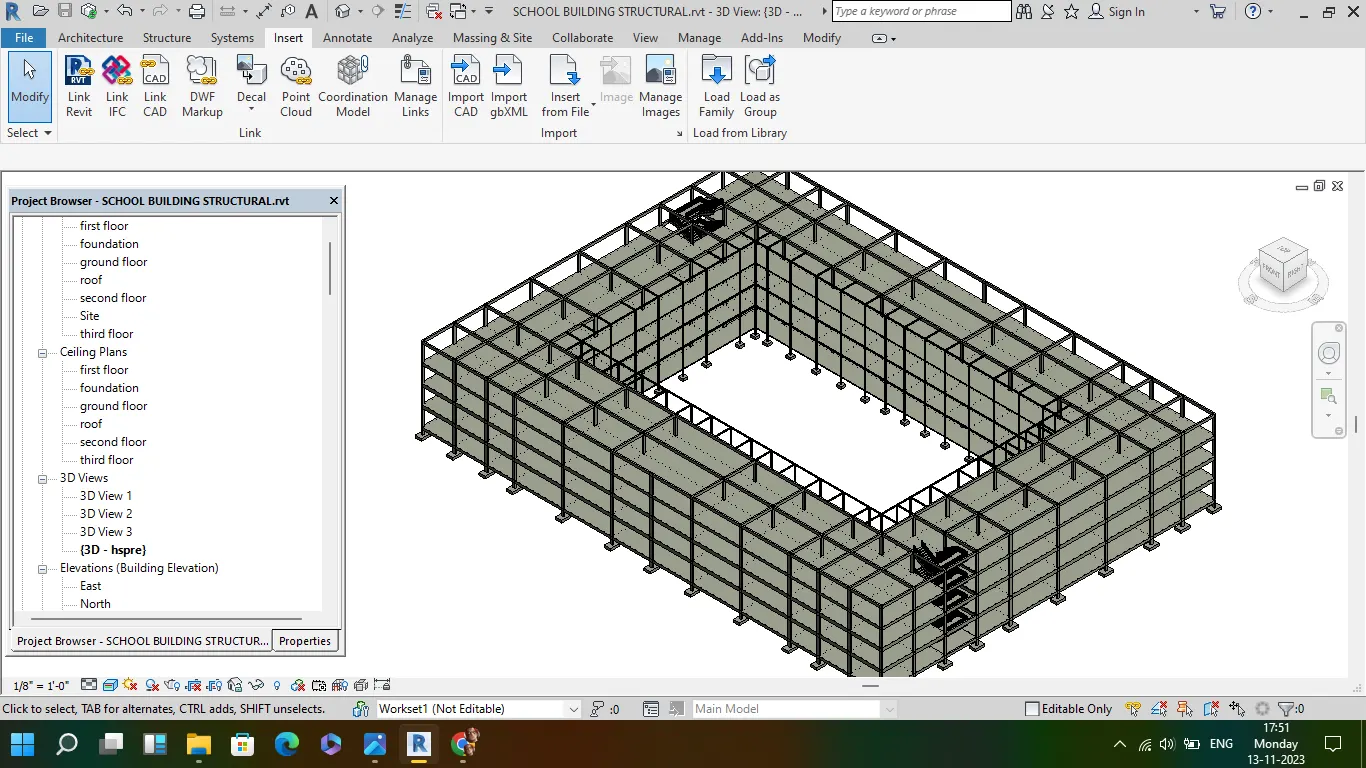
adding the columns of size 9"x18" and 6"x6"
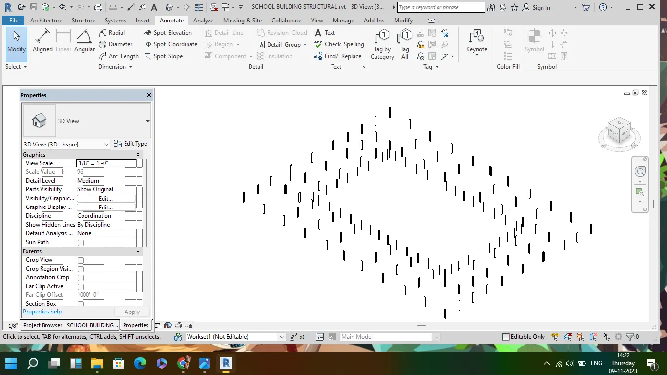
adding beams (9"x18" and 6"x6") accordingly joining with the column and copying the whole column and beam layout in to all respected levels
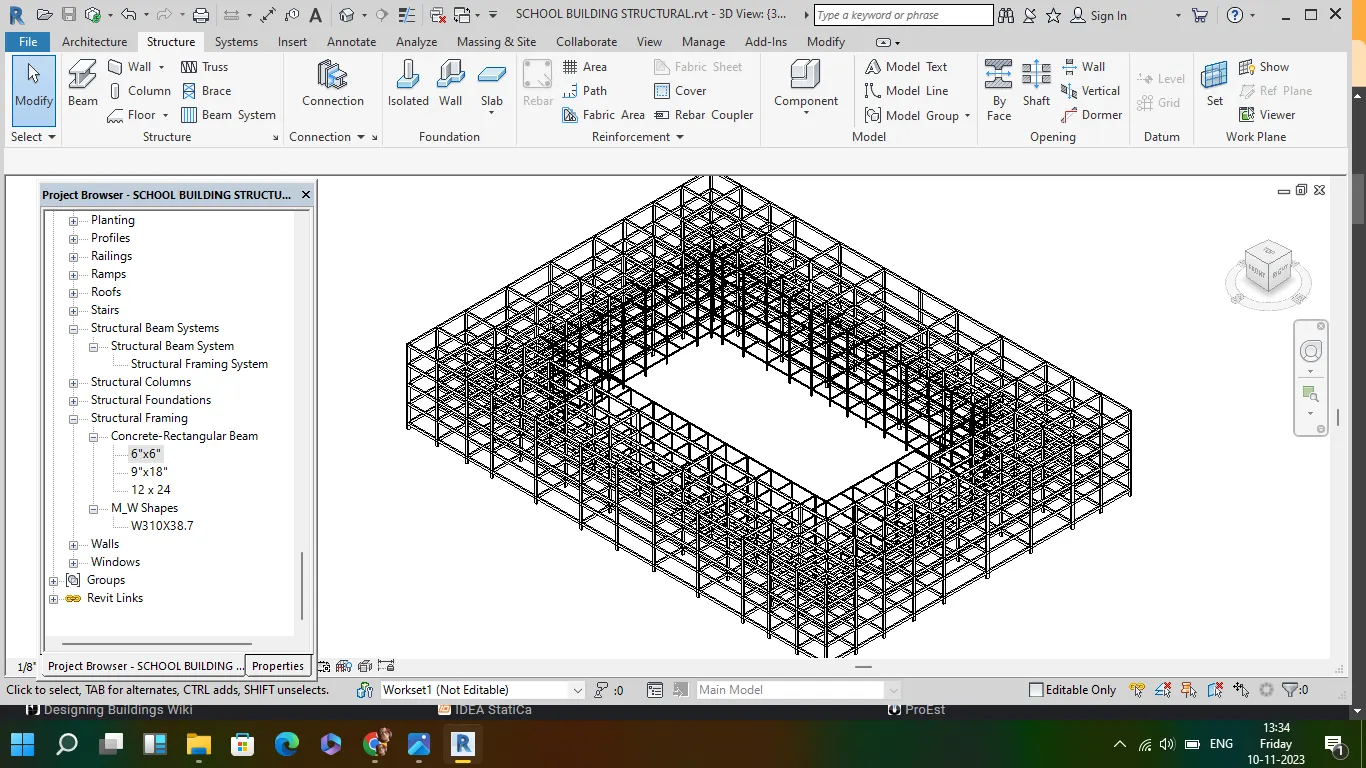
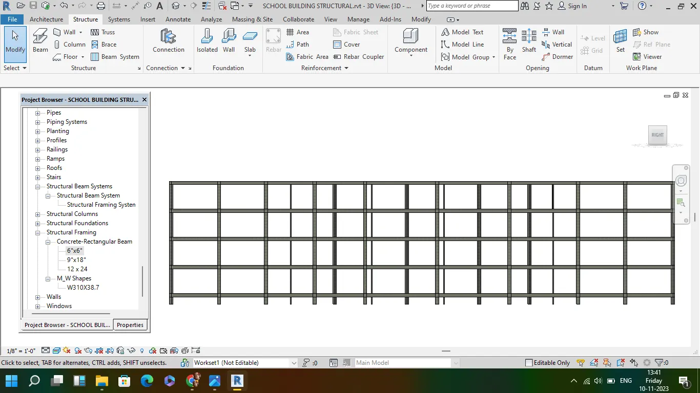
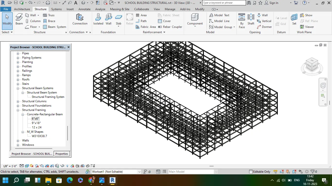
adding of footing into the layout in the foundation level of size 18"x48"x72"
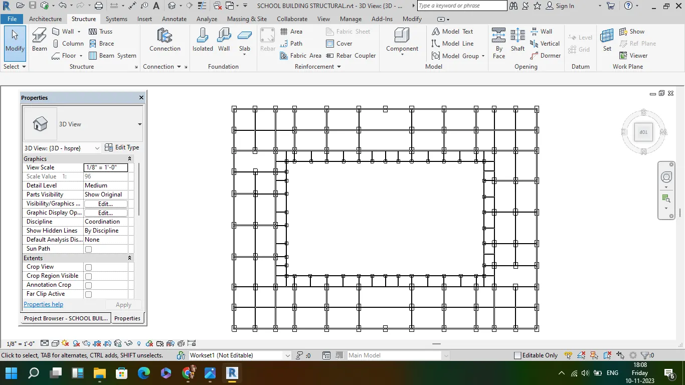
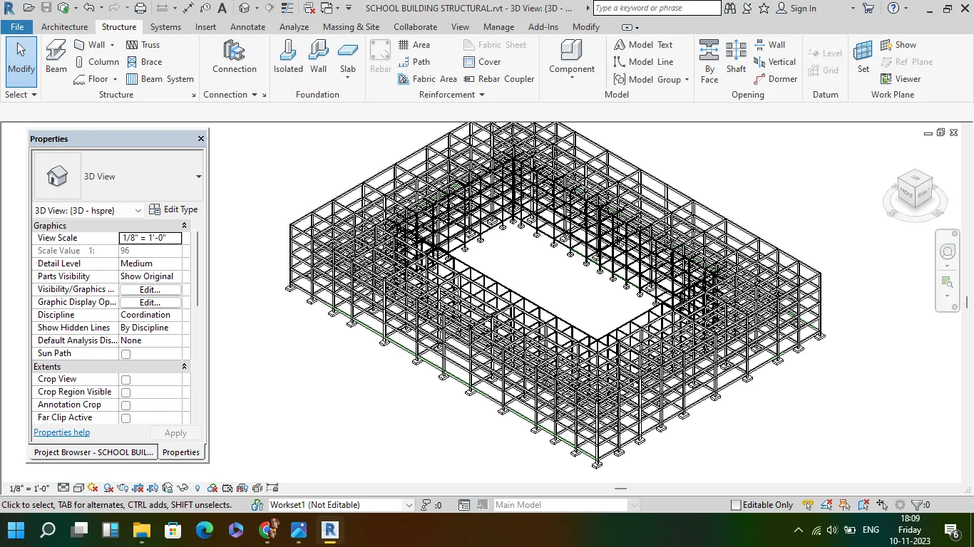
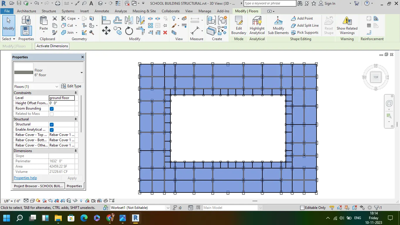
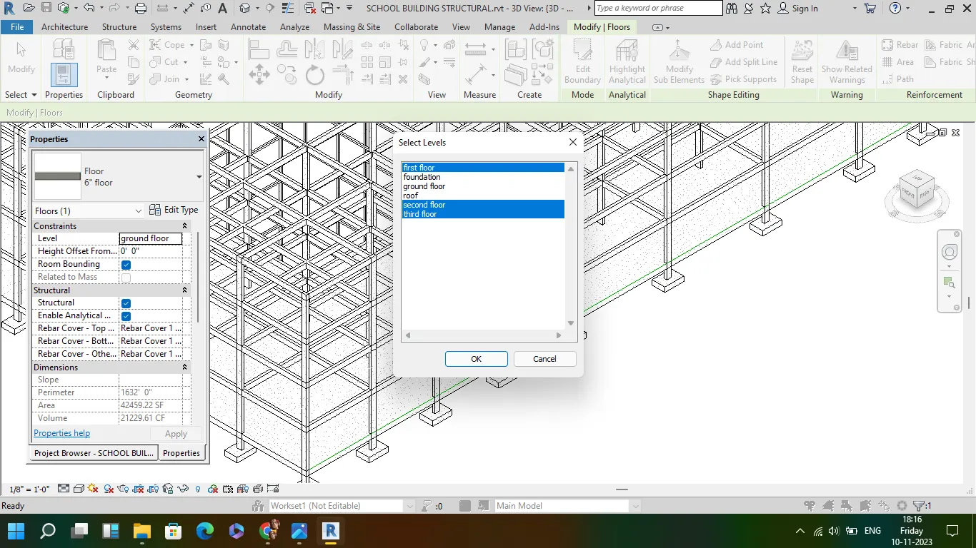
add structural floor to the model, and copying it to all respected floor
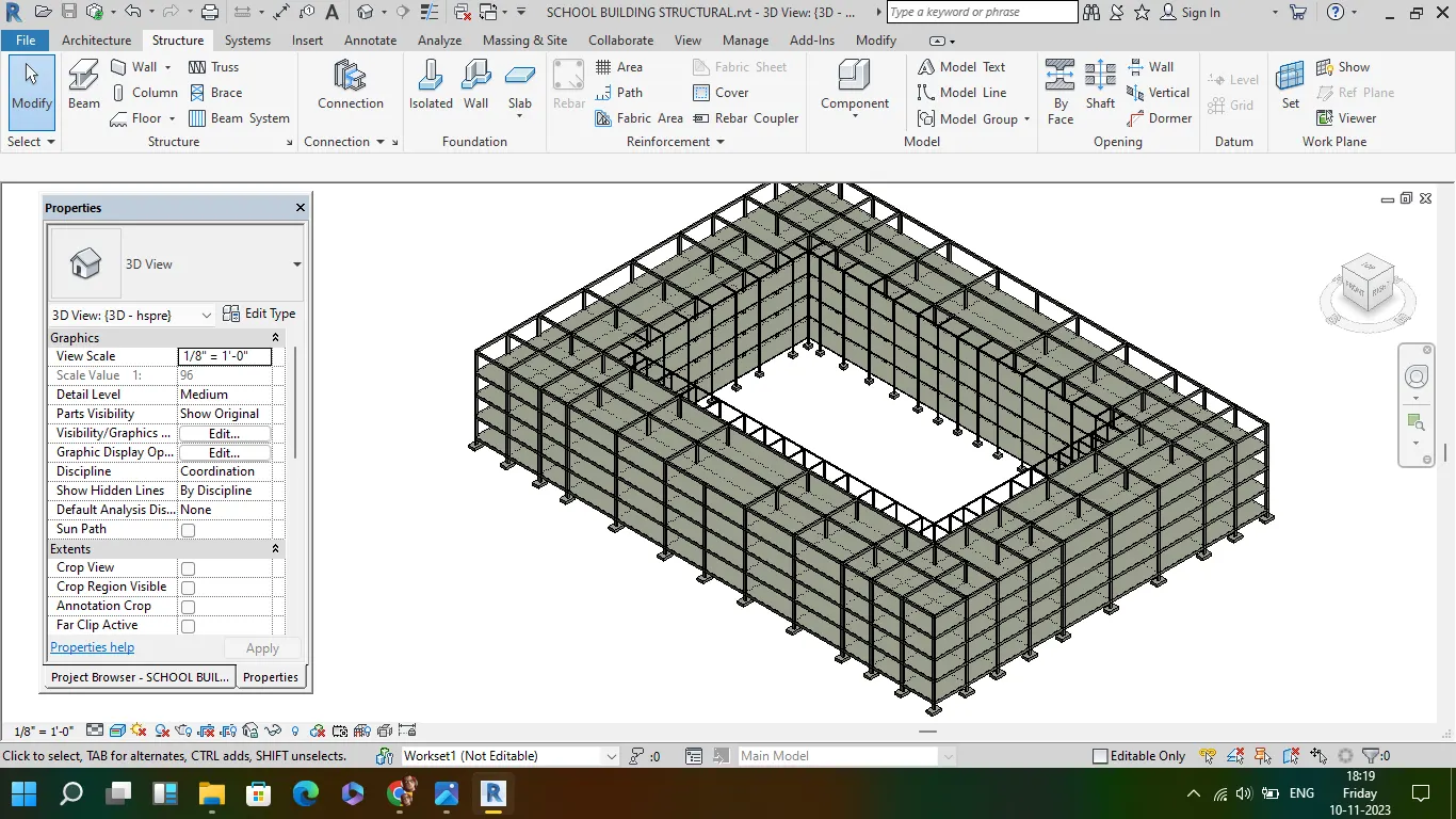
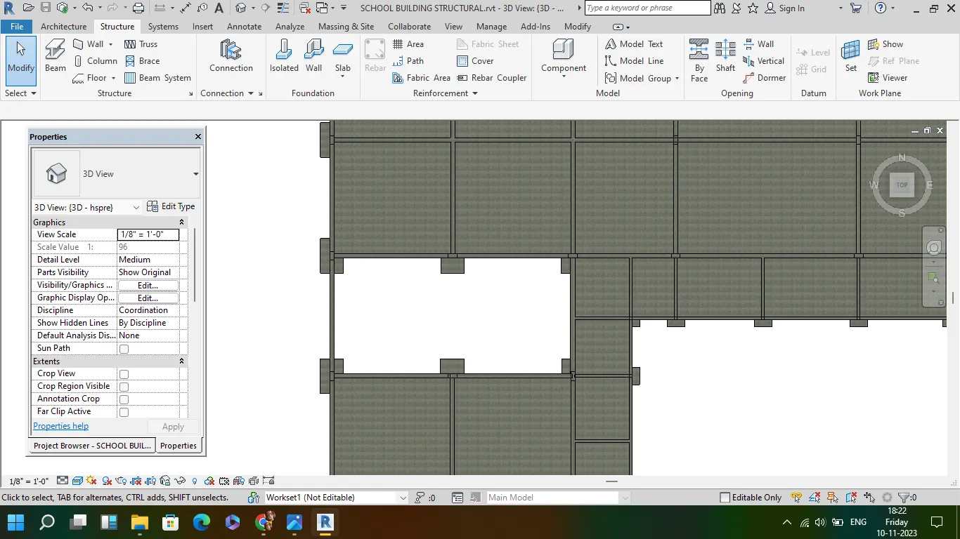
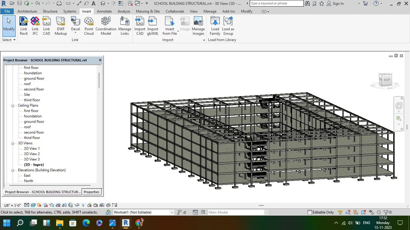
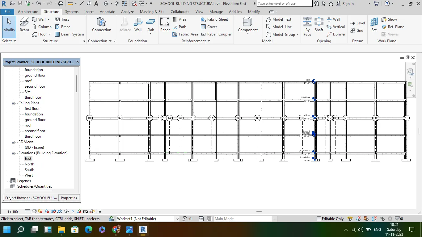
opening for stair, A shaft opeing from ground floor to roof and adding the staicase into model from ground floor to roof
- open the new arch template file and set it to imperial
- go to insert tab and insert the CAD drawing into arch template
- add the grids accordingly as per the CAD drawing to place further structural components in to it
- open the new structural template and set it to imperial and save it
- go to insert tab to insert the revit drawing ( insert the arch drawing into structural drawing)
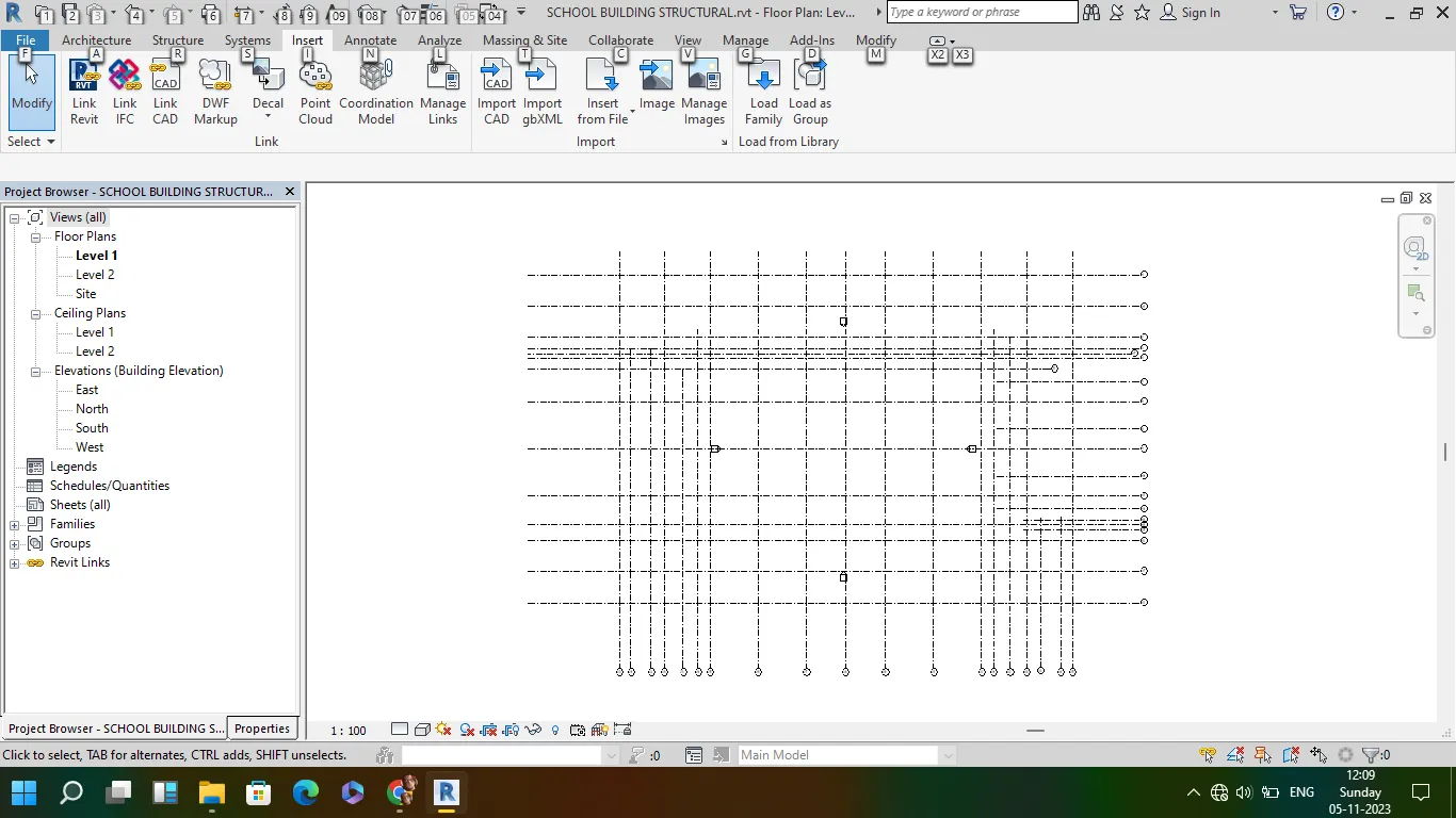
- go to colloborate tab to collaborate the arch file into revit file collaborate it with in the network
- save the file , so that it will be saved as the central file
- go to collaborate tab and to synchronize the model, select synchronize with central and select compact central model
- go to copy moniter and copy the link file into structural layout file
- the model will be synchronized and it can be used by other users
- create the levels for different floor ( foundation, ground floor, first floor, second floor, third floor and roof
- now time to add structural components into layout with reference to the grids add ( footing in the foundation level, and start adding the column from foundation to ground floor )
- draw the beam along the coulmn , where its necessary
- copy the column and beam and paste it to each floor levels, so that the complext structural elements is formed
- draw the floor in ground floor level, with reference to the grids and copy the floor and paste it to each respected levels
- to show the openings for staircase, go to shaft opening , draw the required area to be open and open the floor gap for stairs ( from ground floor to roof)
- add the stairs to the shaft opening area from ground floor to roof
4
Aim:
Using the architectural model, include the following components based on the type of structure selected
a. Wall Layout with appropriate material and finishing
b. Exterior façade with fancy finish
c. Interior partition walls to size rooms
d. Components to add details to a room ( Desk, Chair, Lighting, Plumbing fixtures)
e. Add components such as stairs Elevators
f. Have at-least one side of the building with curtain walls and glass panels
g. Include interior and exterior lighting fixtures
h. Place proper topographic components from outside ( Trees, Parking, Plants) to add details to the model
creating new wall layout for school building in arch template
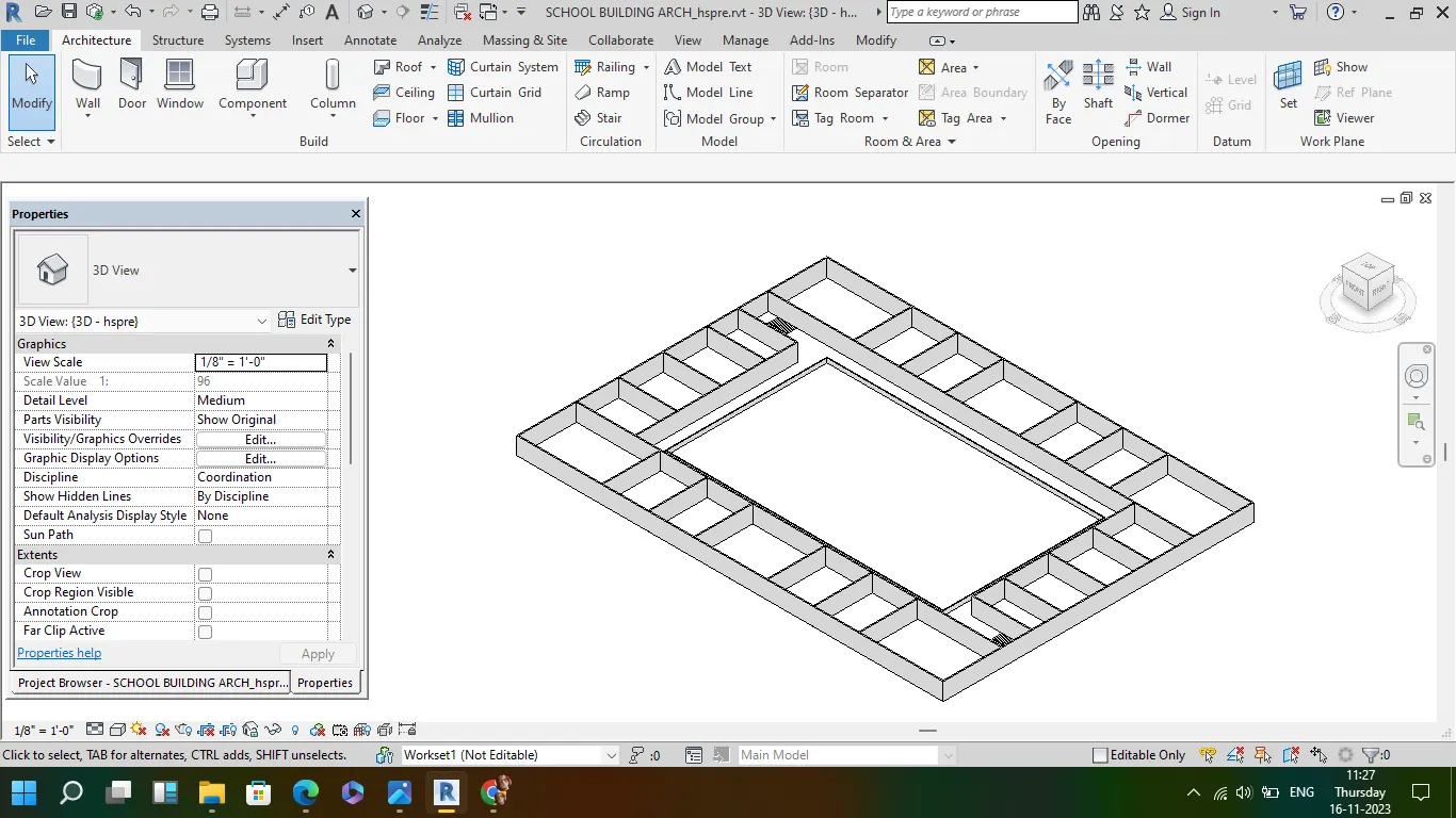
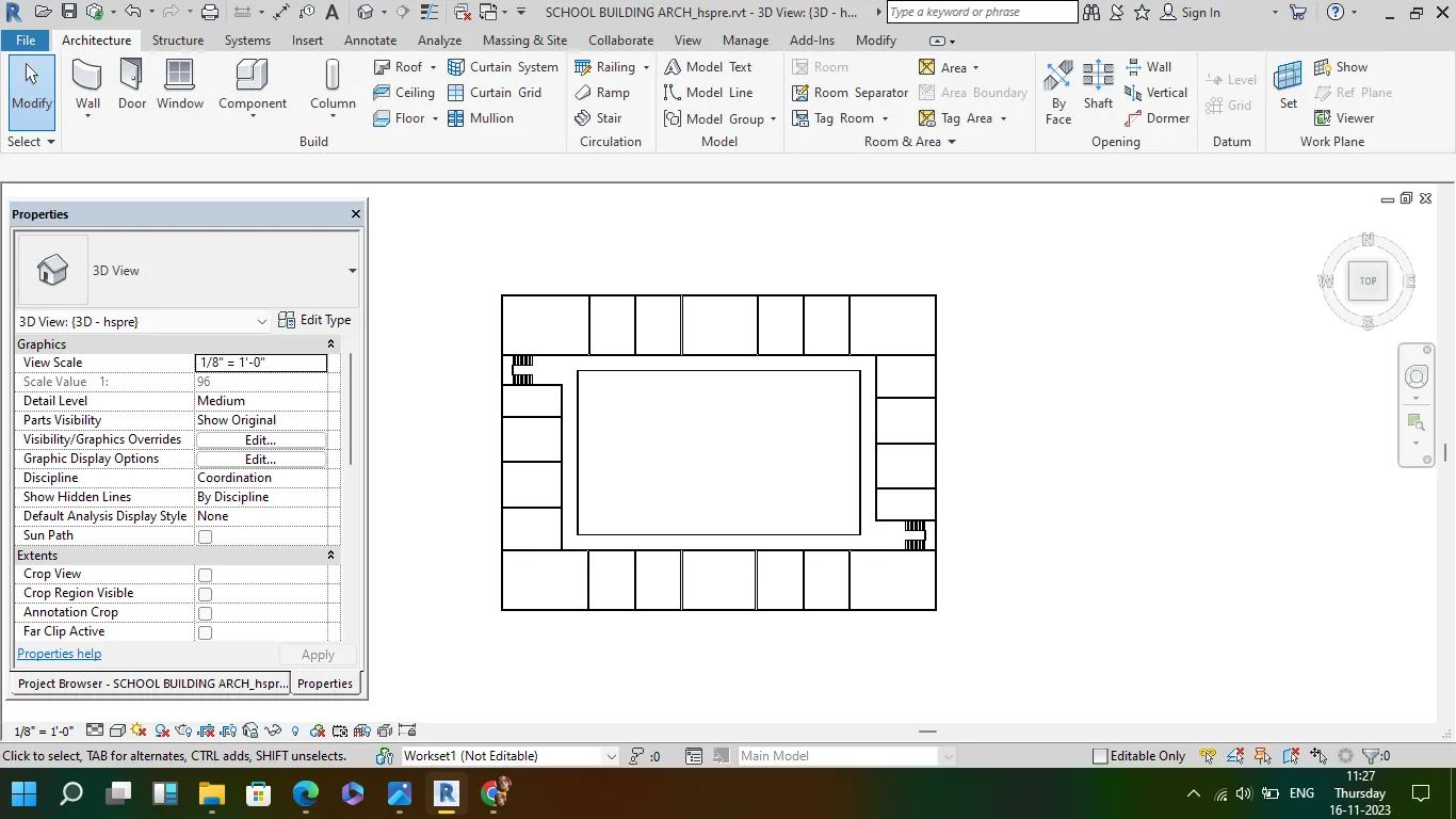
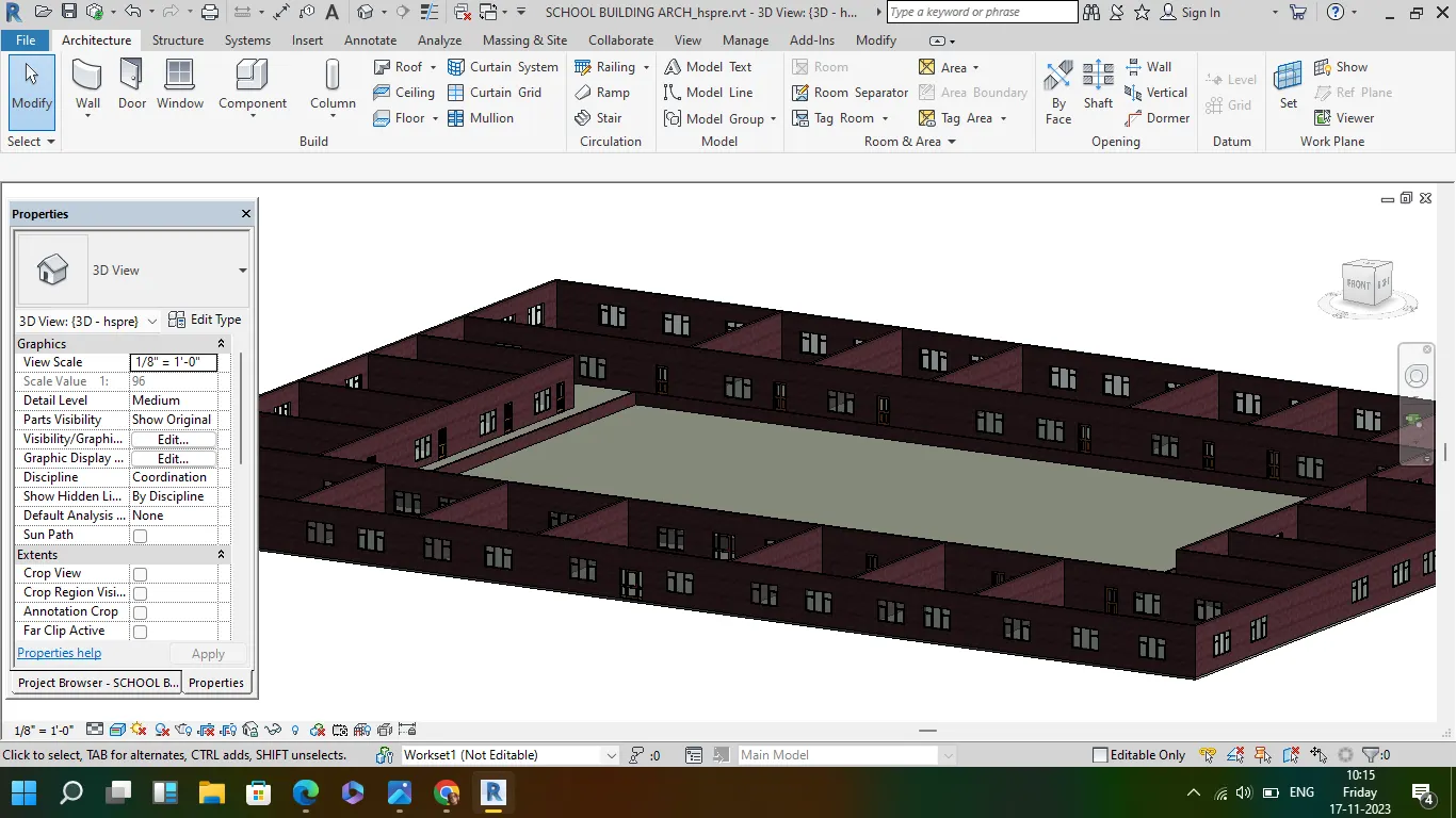
assigning wall material as brick masonry and placing window and door at required position
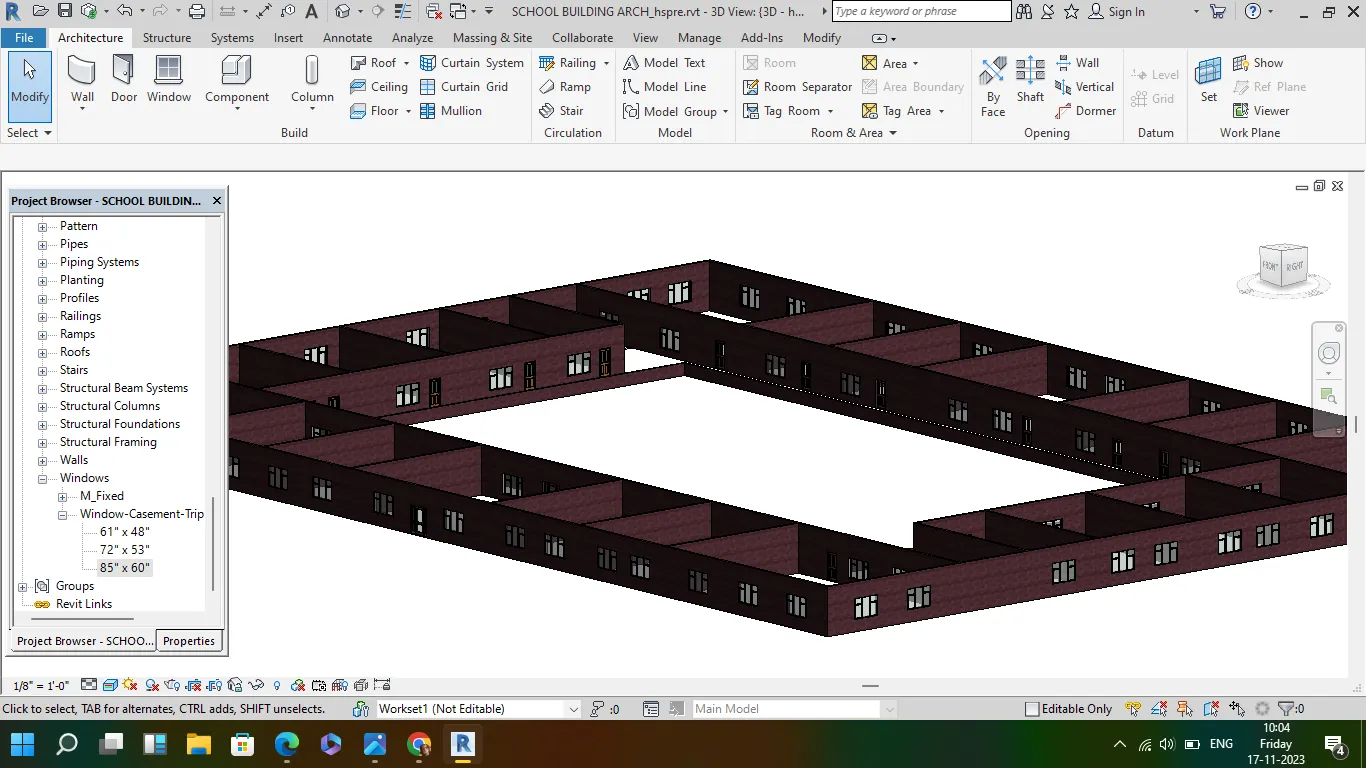
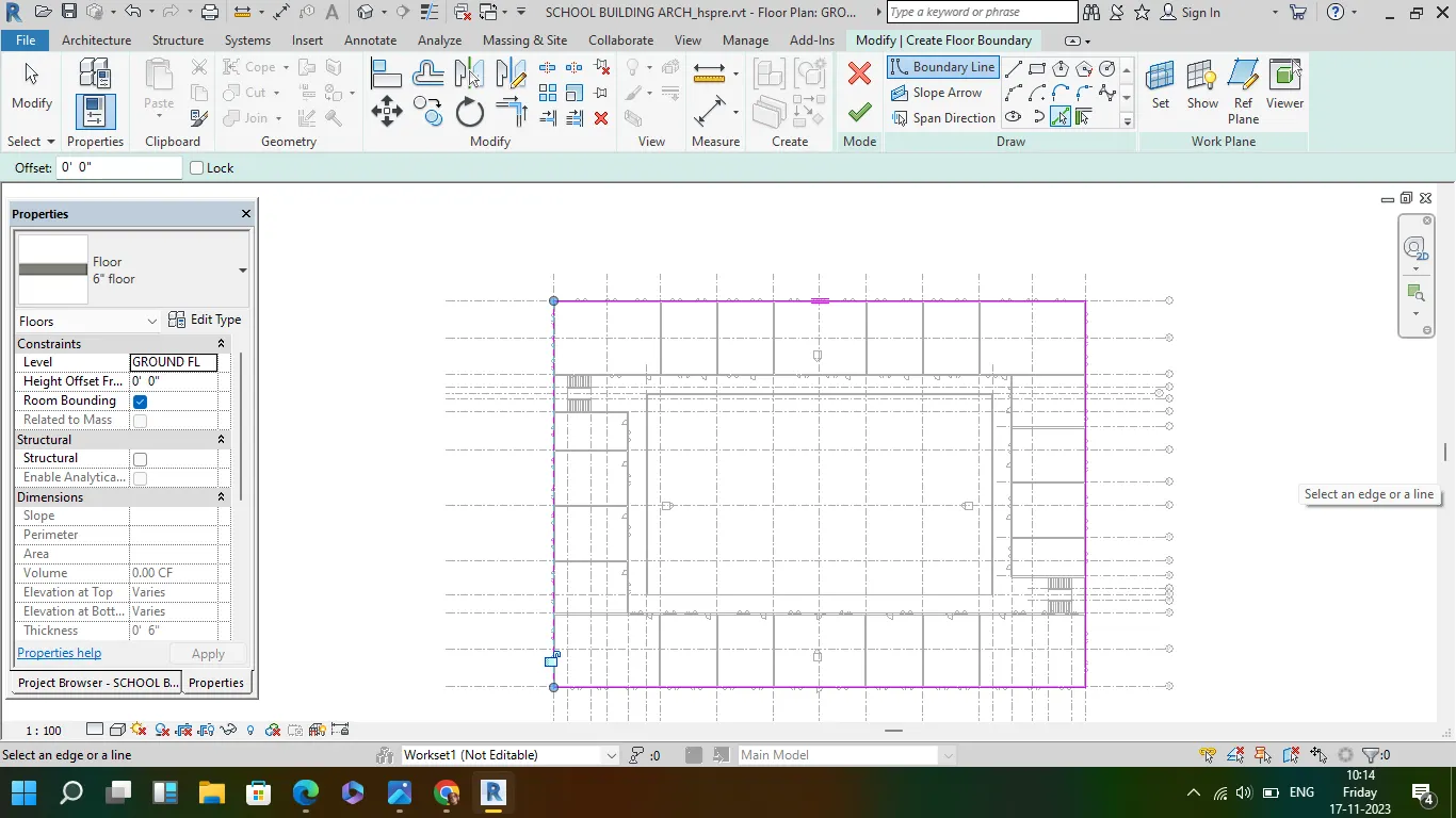
drawing the floor of 6" at ground floor
providing partition walls for washroom and bathroom and adding all plumbing fixtures at required place in washroom
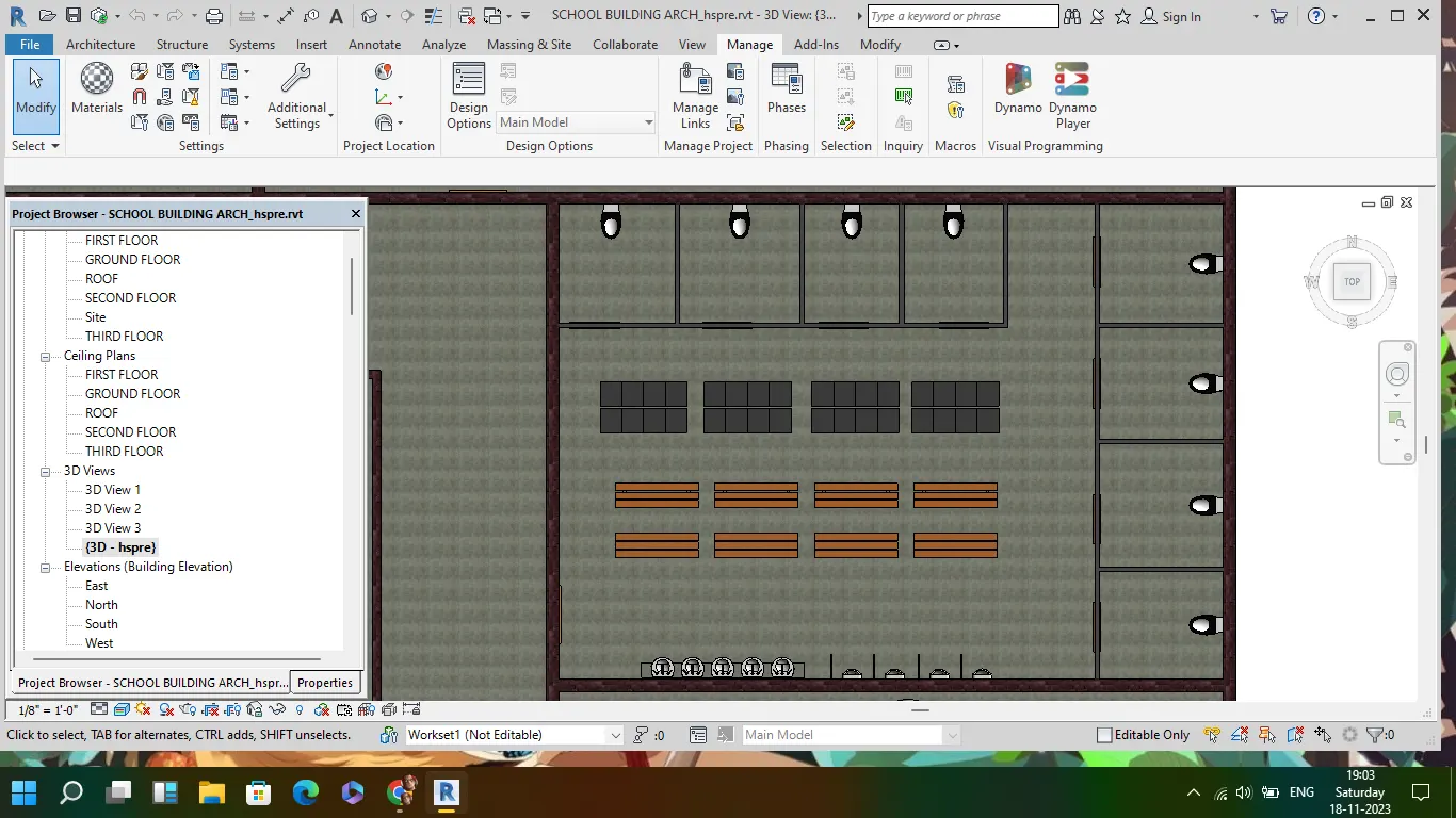
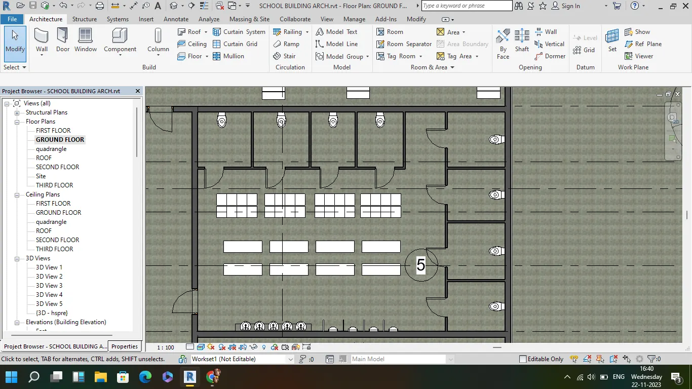
placing all the school furniture components
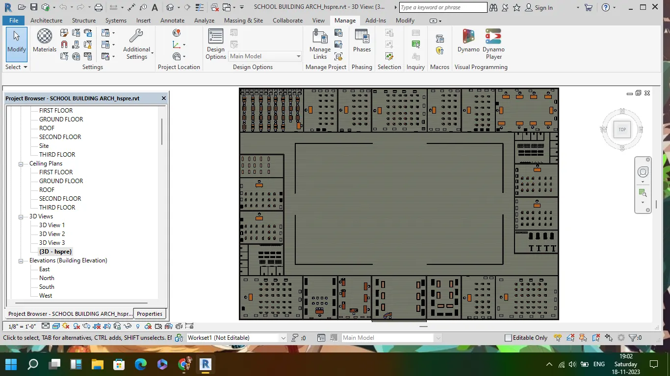
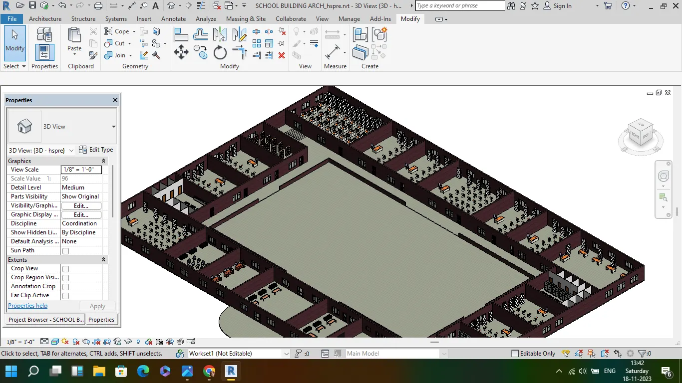
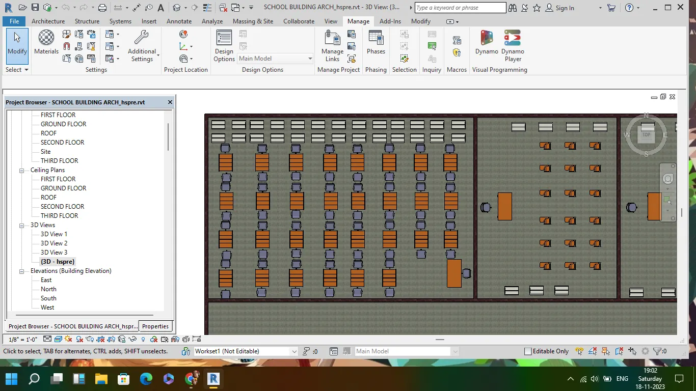
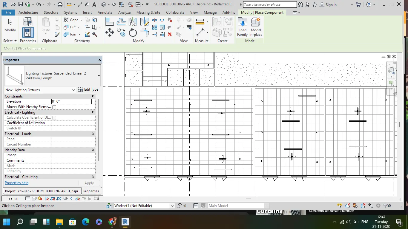
creating the cealing in each floor and adding the internal lighting fixtures
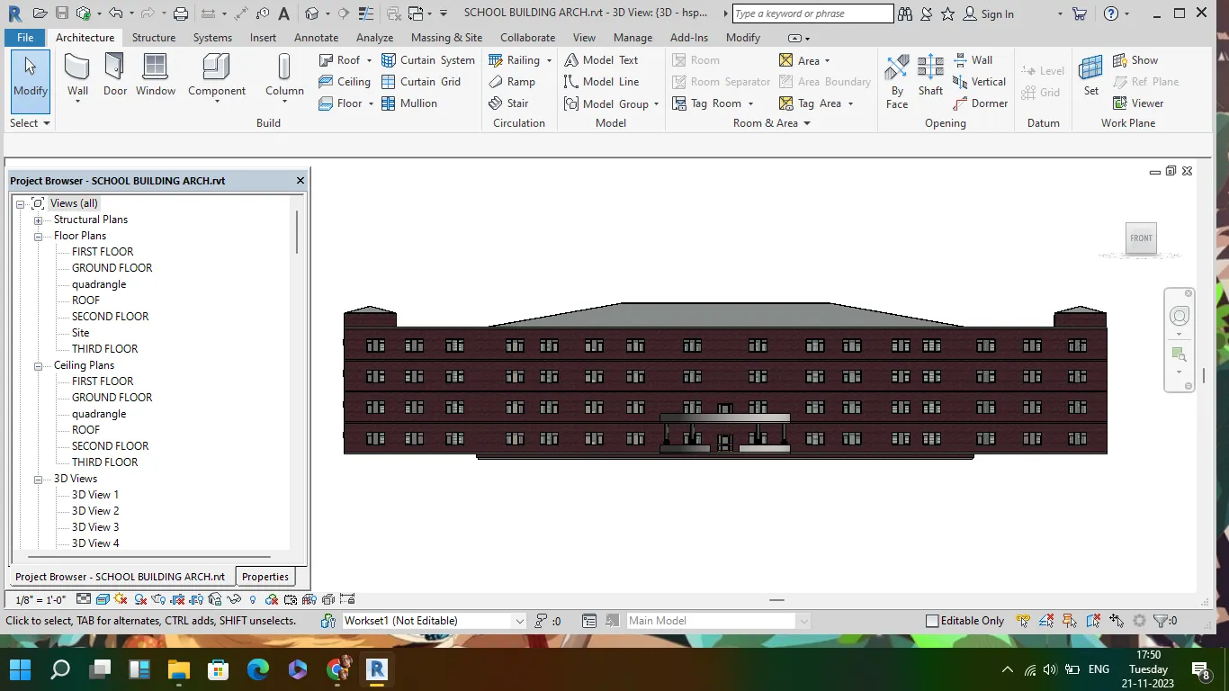
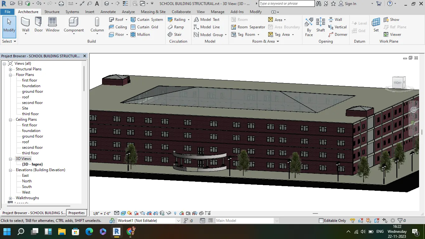
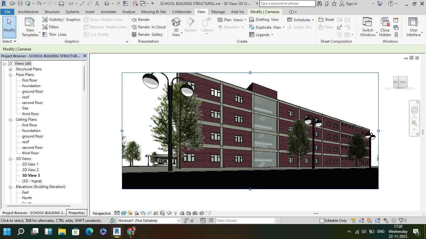
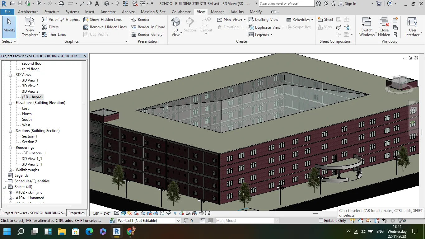
exterior faced of building
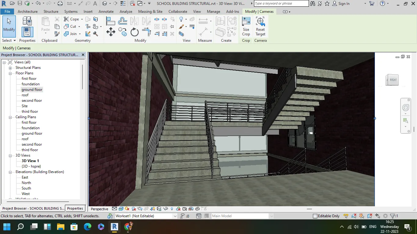
staicase provided to connect each floor
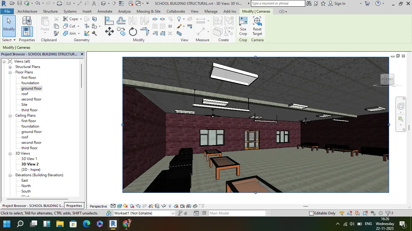
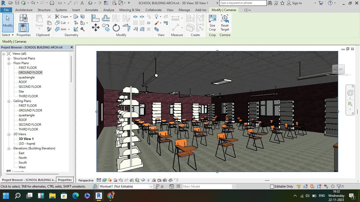
lighting fixtures and furnitures
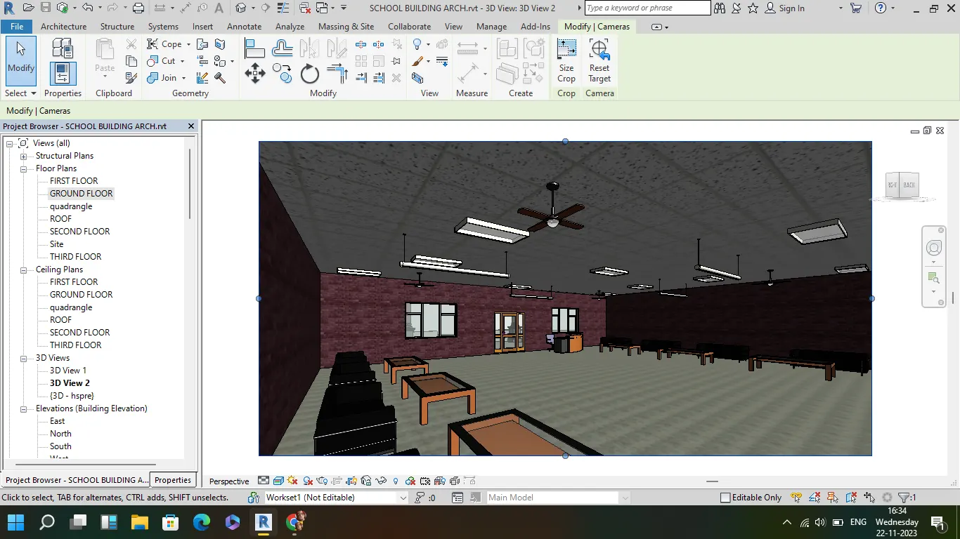
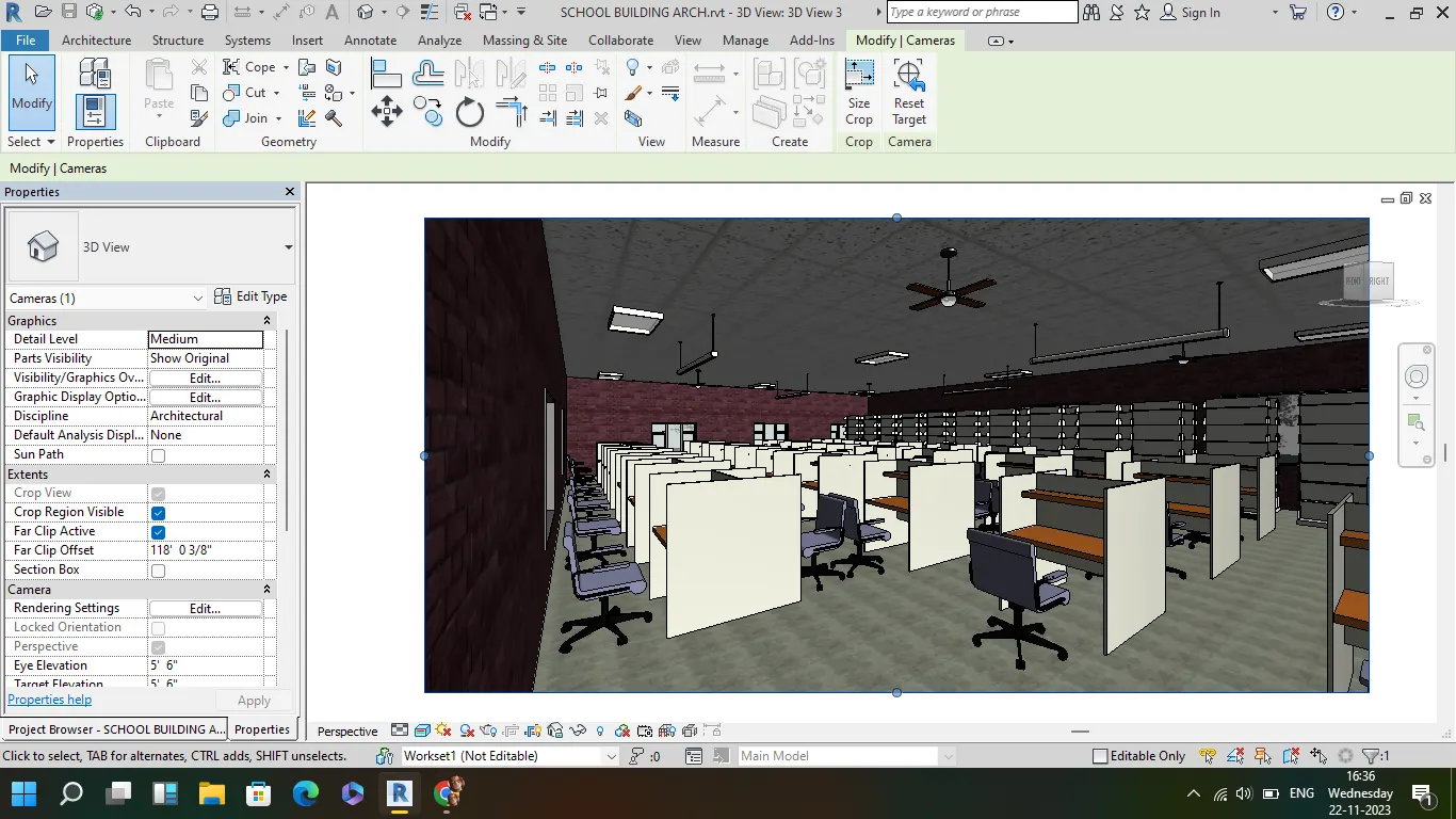
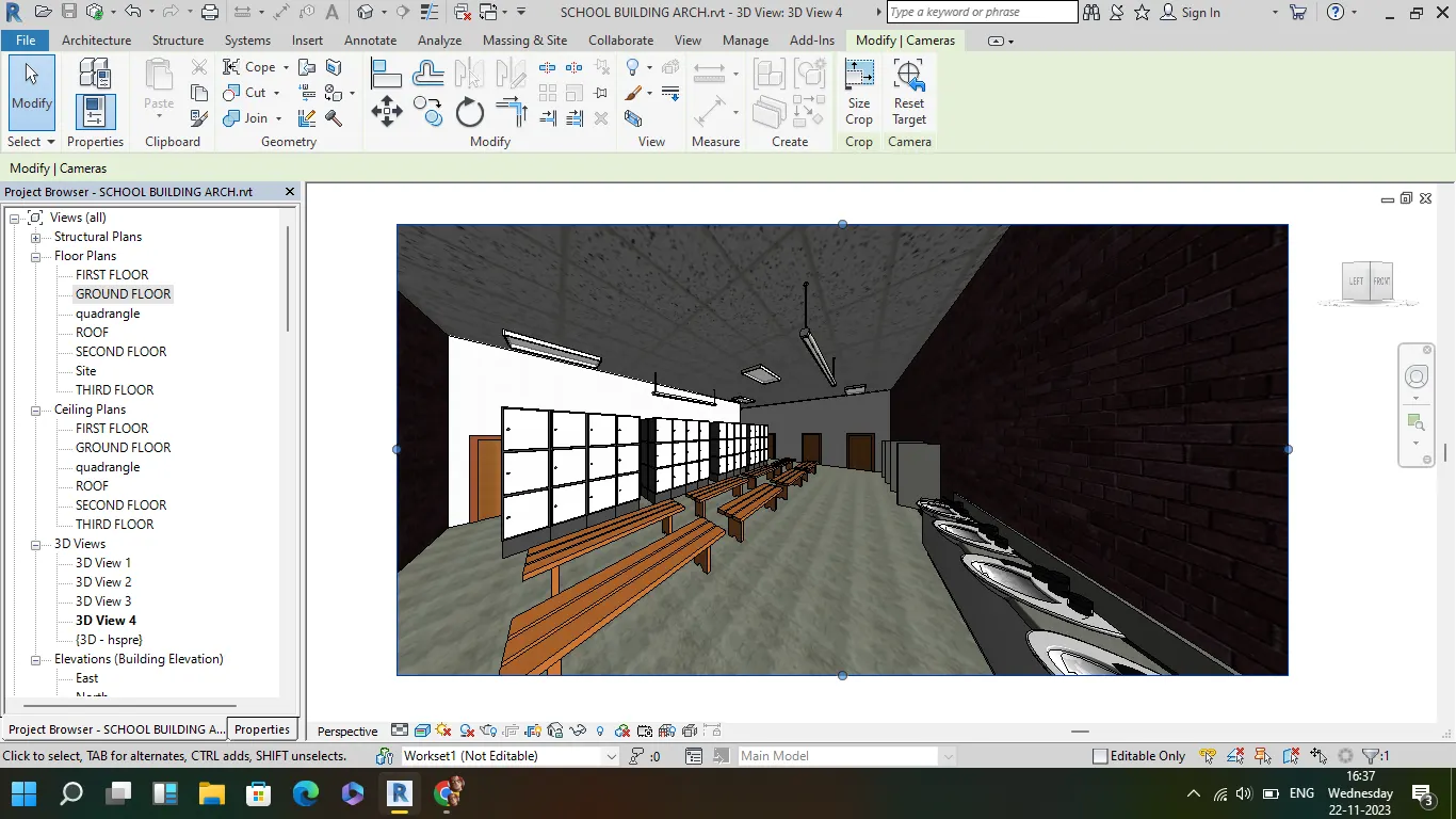
plumbing fixtures
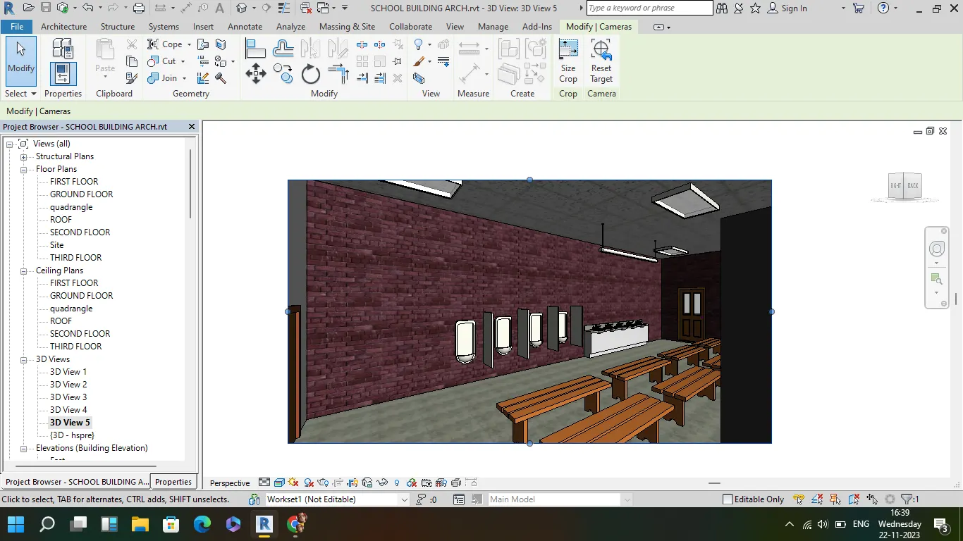
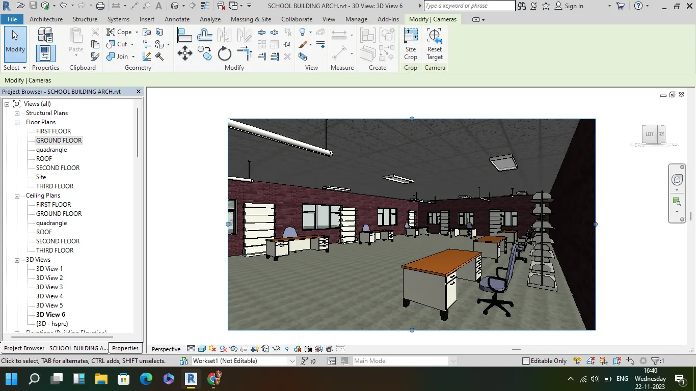
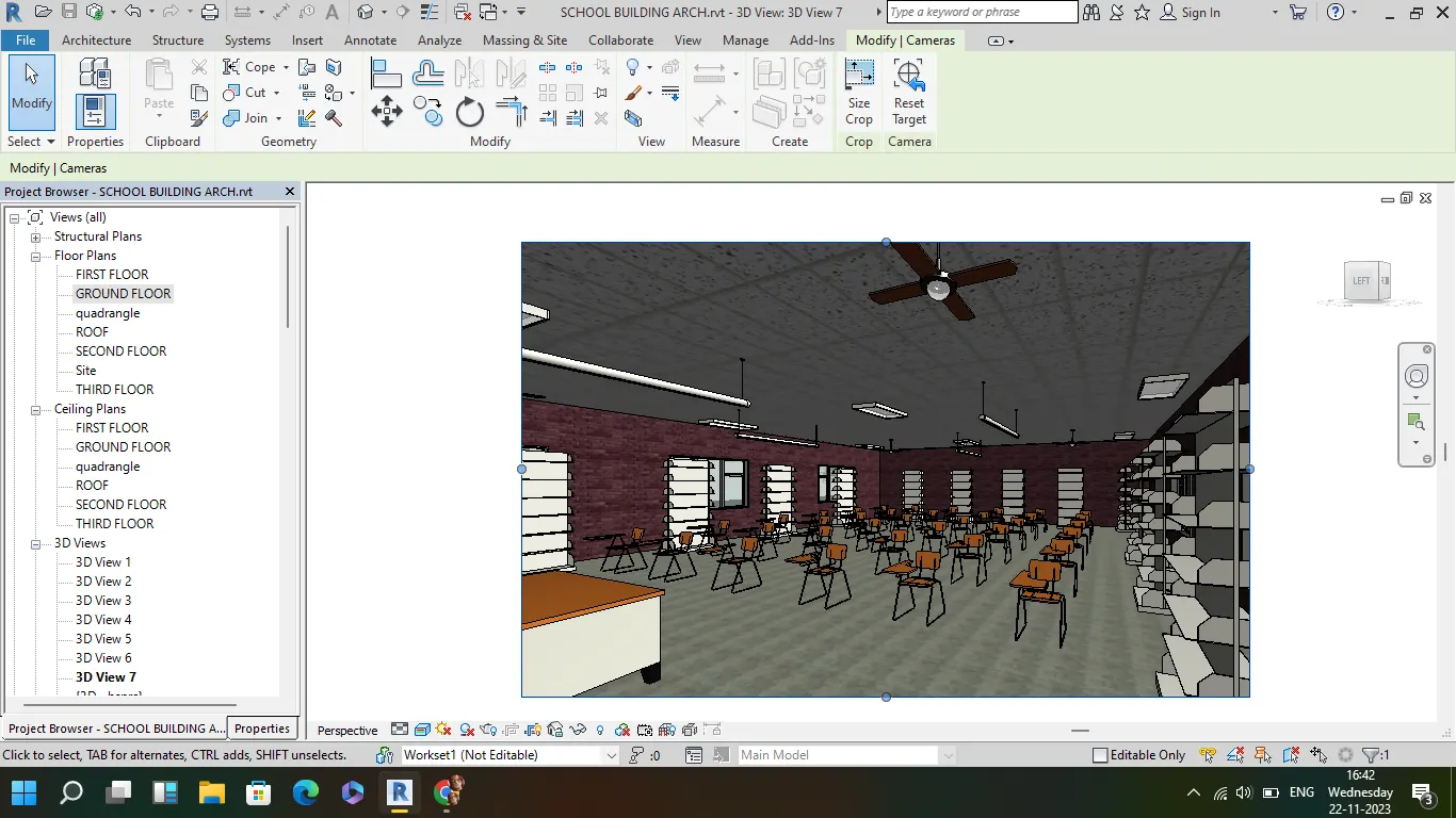
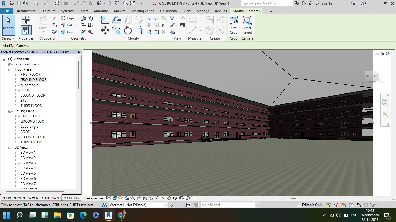
external lighting fixtures, trees and parking
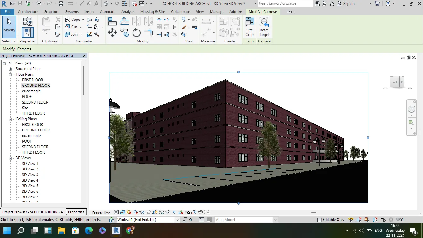
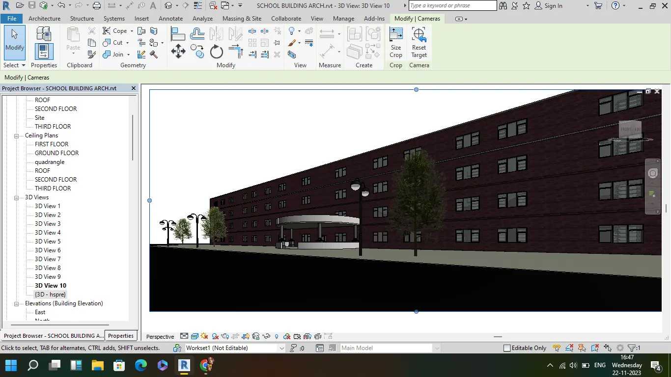
doors and window components
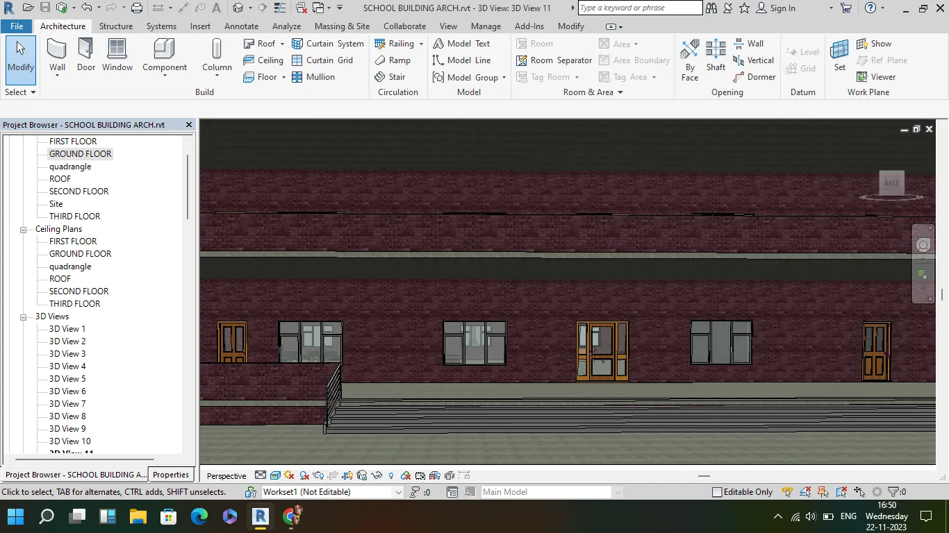
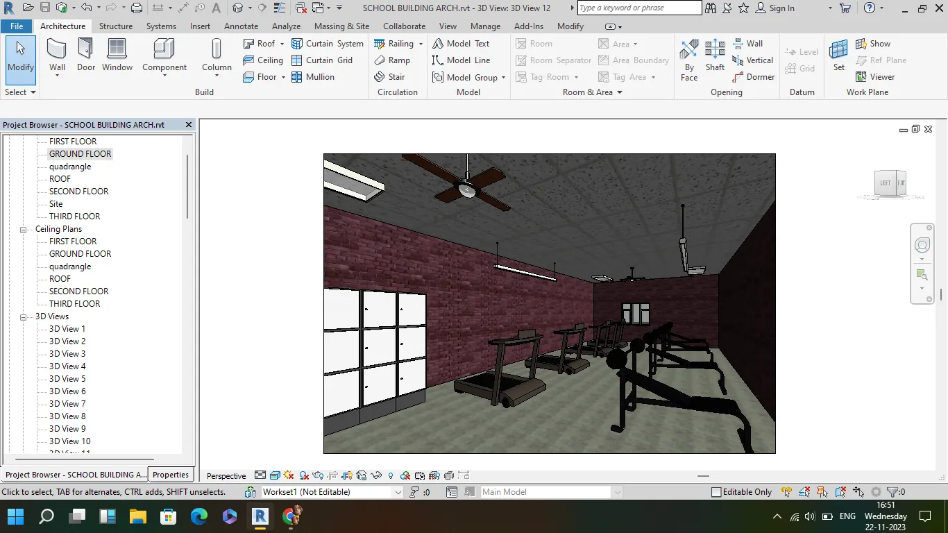
one side wall is glass panel and curtain wall
5
Aim:
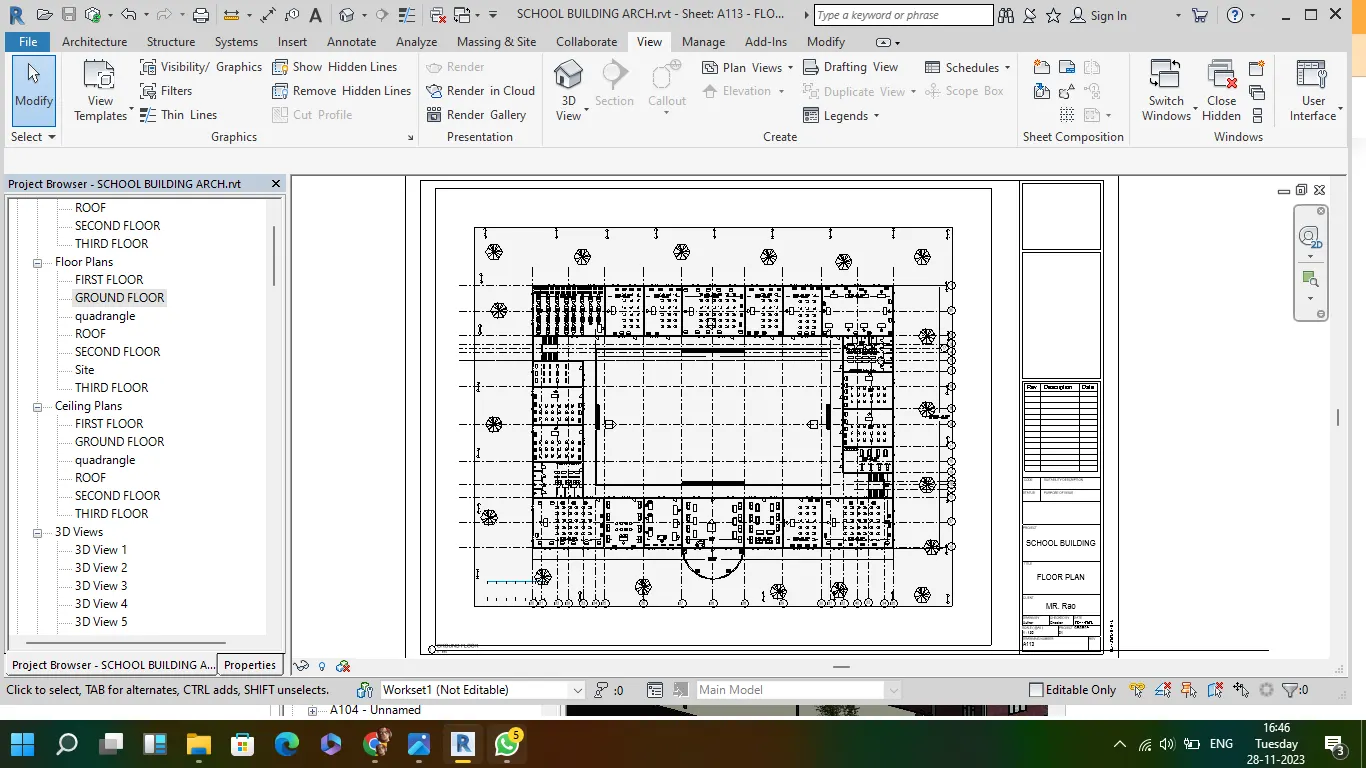
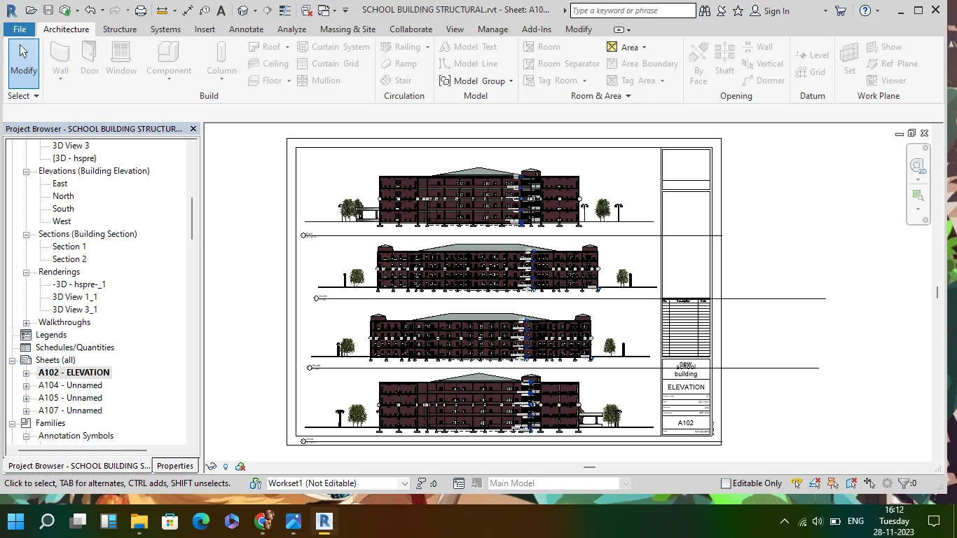
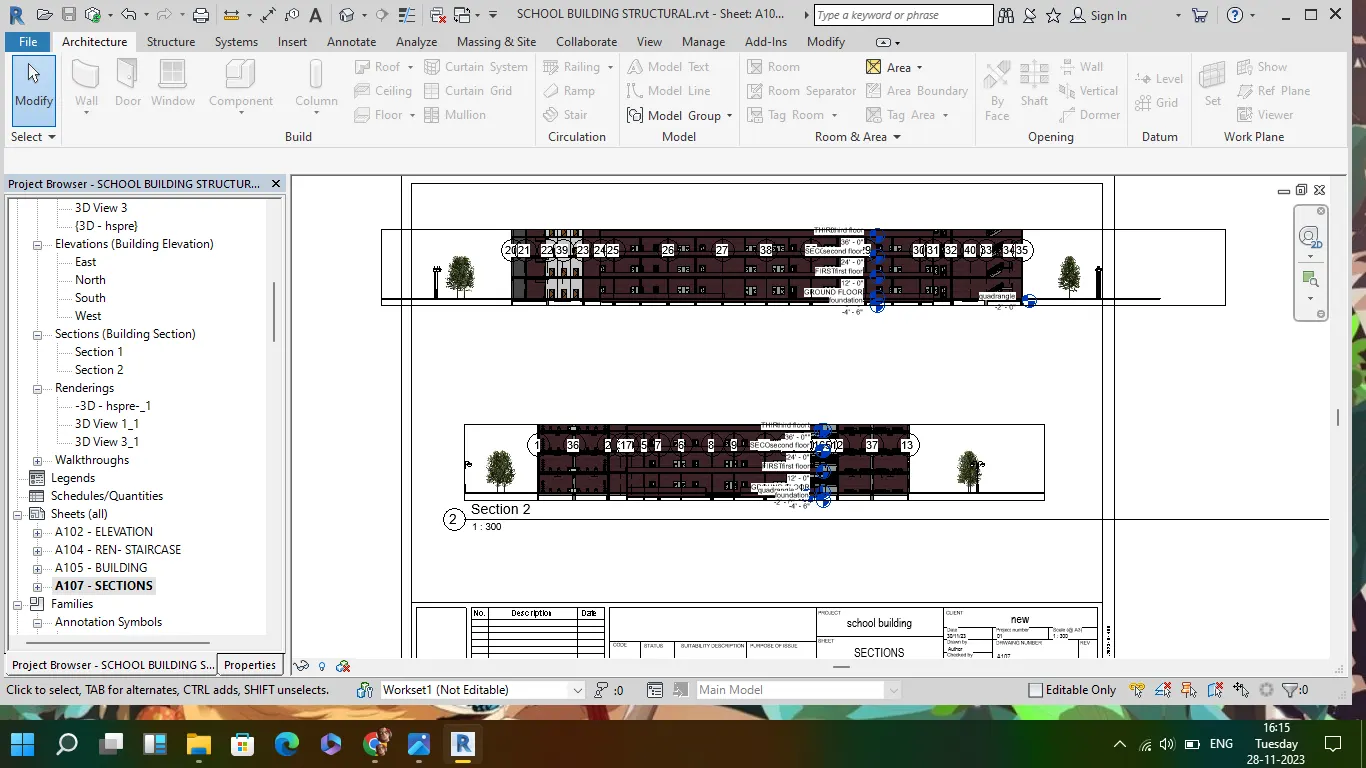
To provide a set of drawings in an architectural and structural model to list the following details with categories and appropriate sheet templates included
a. Floor Plans with Annotations
b. Elevations
c. Sections
adding sheet templates
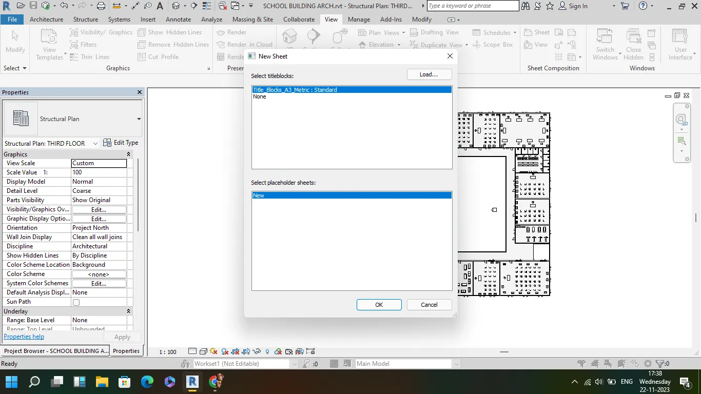
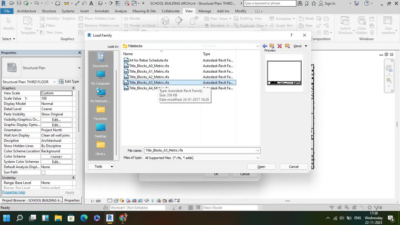
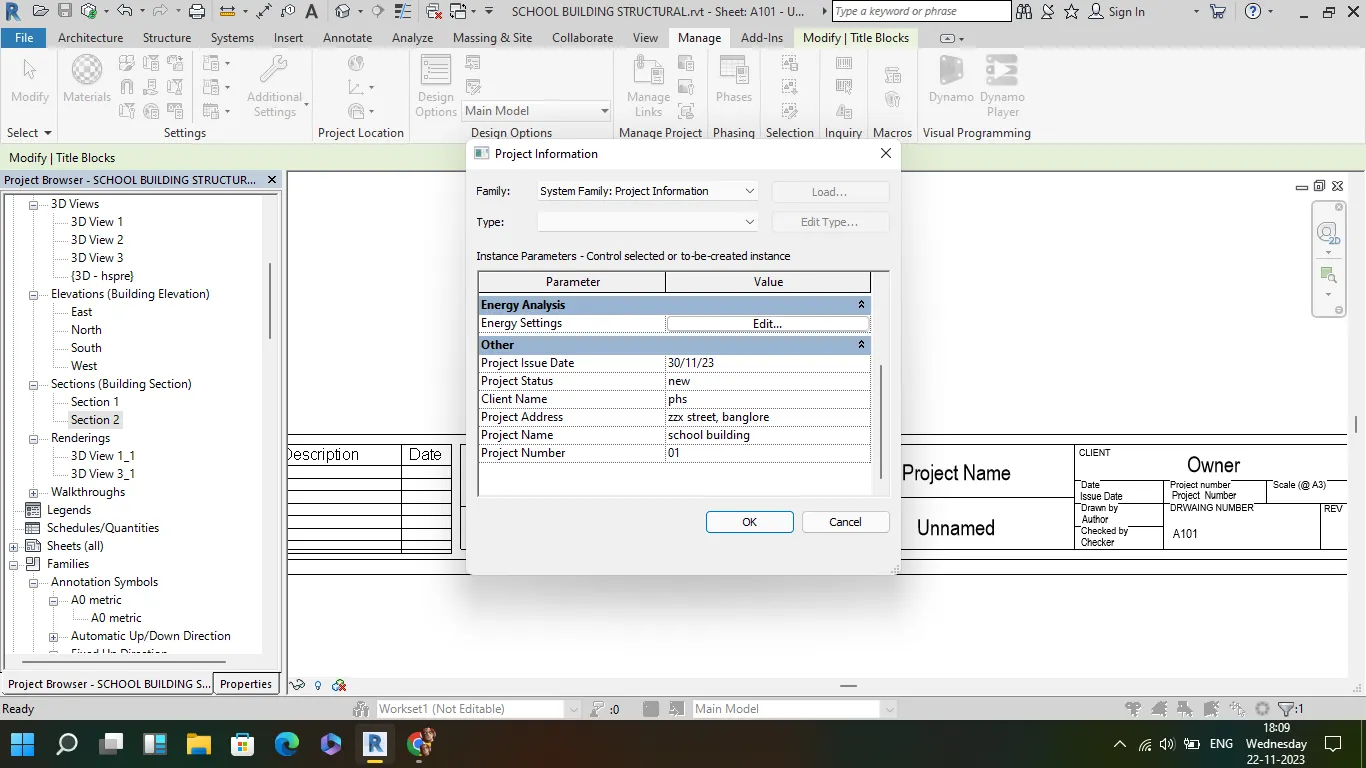
- go to view tab and add sheets
- load the required size of sheets from the family library
- go to manage tab and project informantion
- add all the details of project information ( name of client, project type, date of issue and drawn by )
- after adding the information , drag the views to be inserted into sheet template and place it into sheet
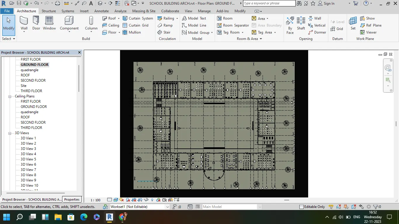
floor plan with annotation
elevations
section drawings
6
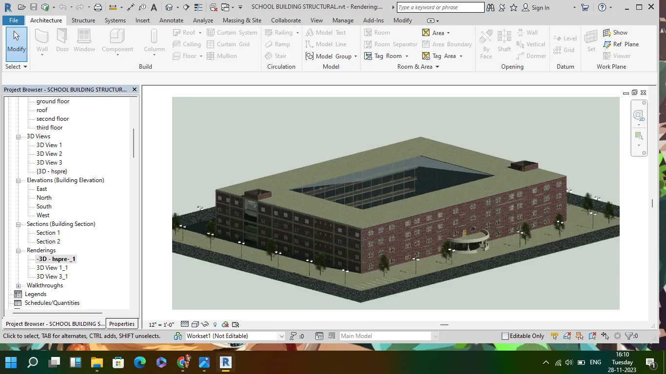
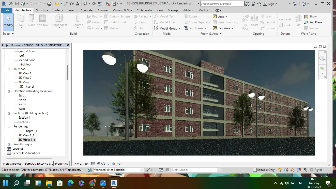
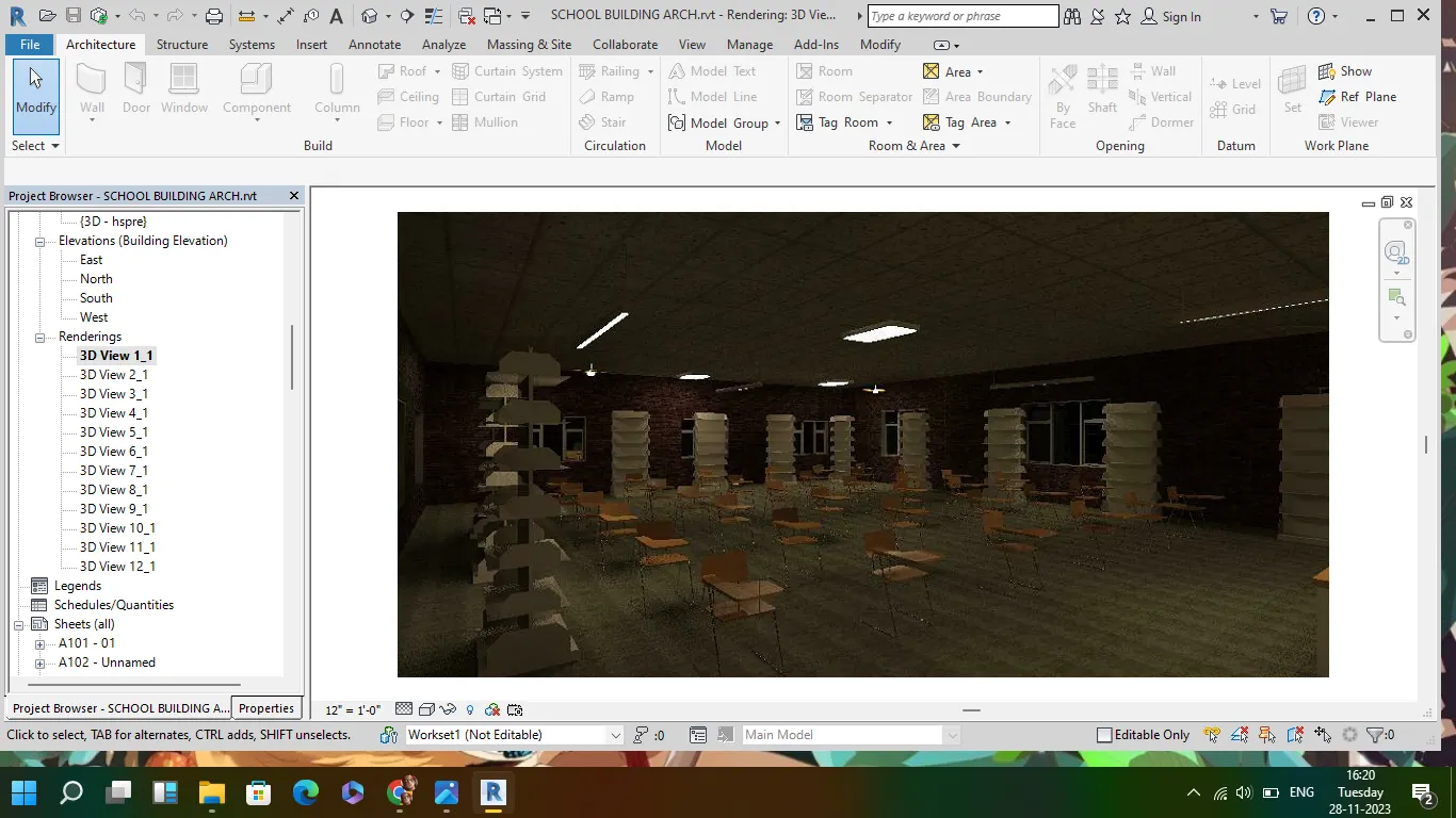
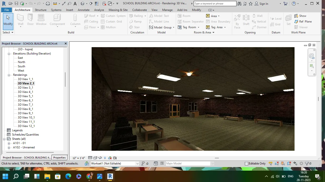
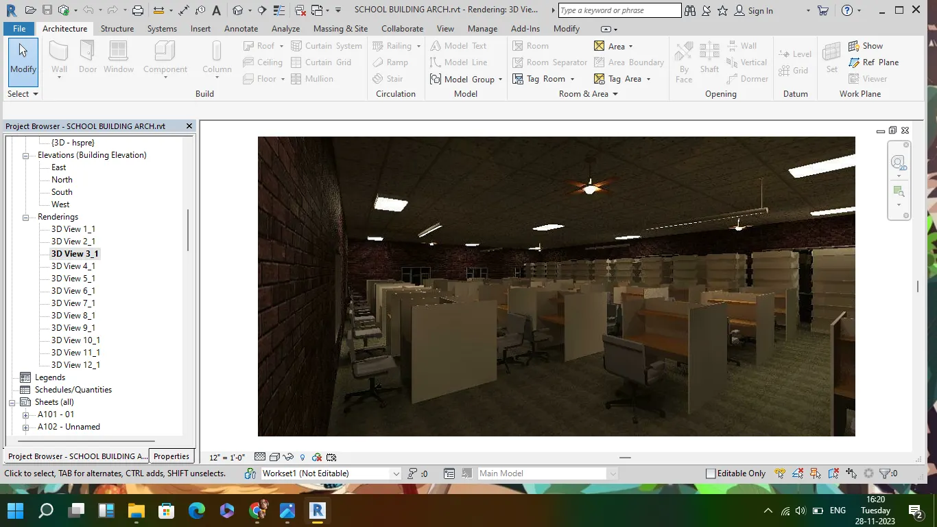
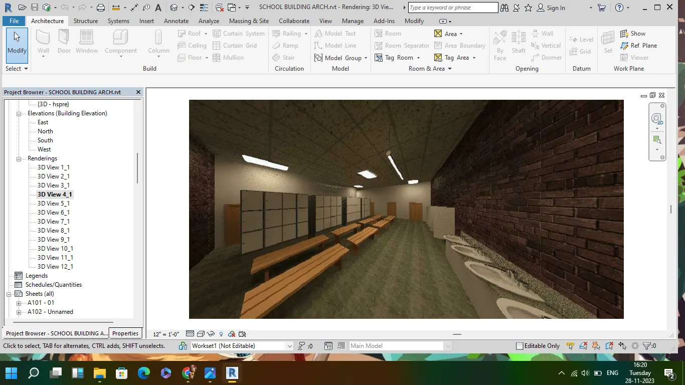
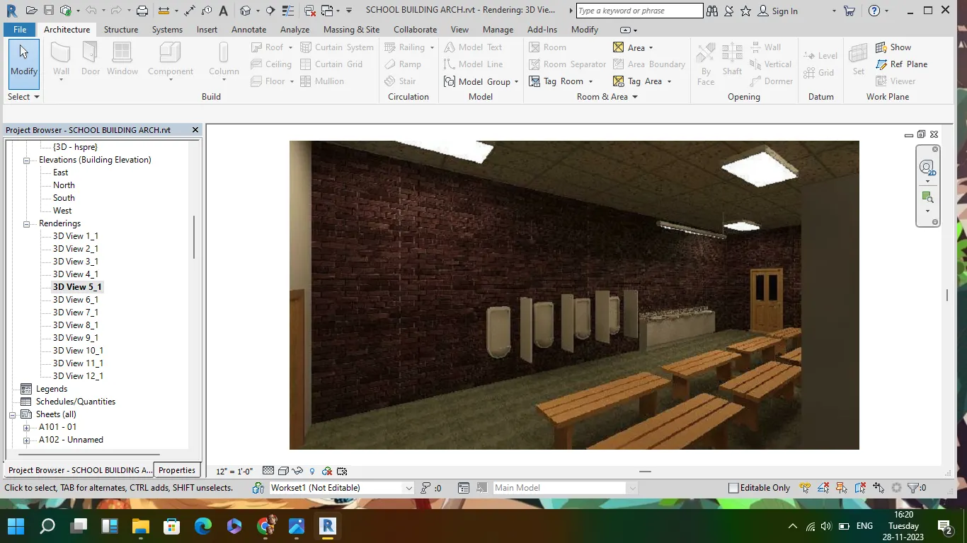
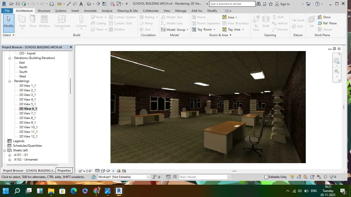
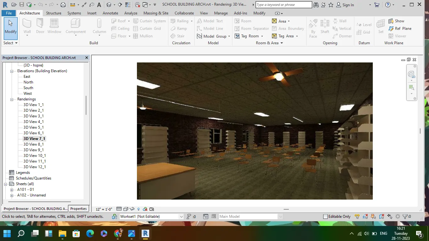
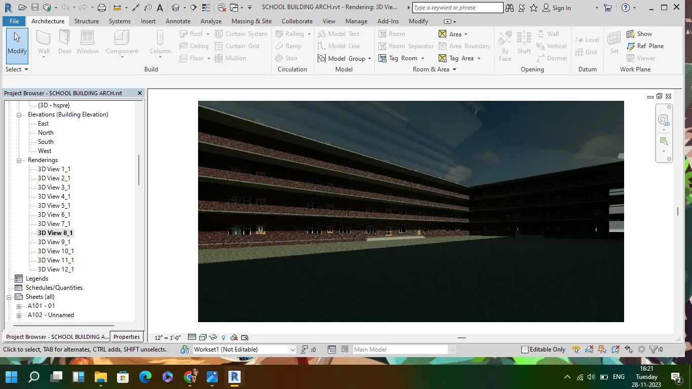
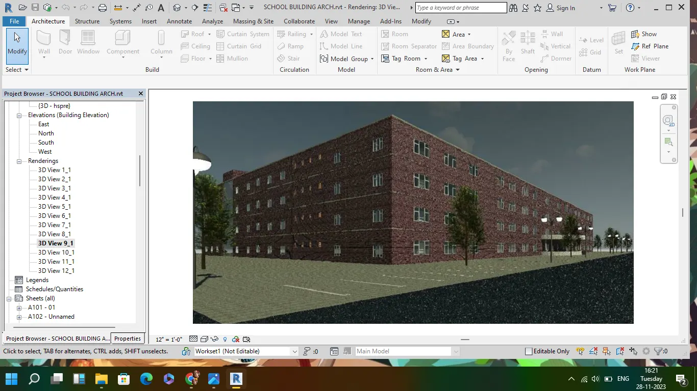
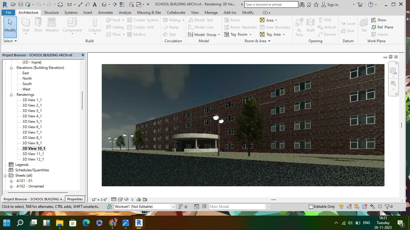
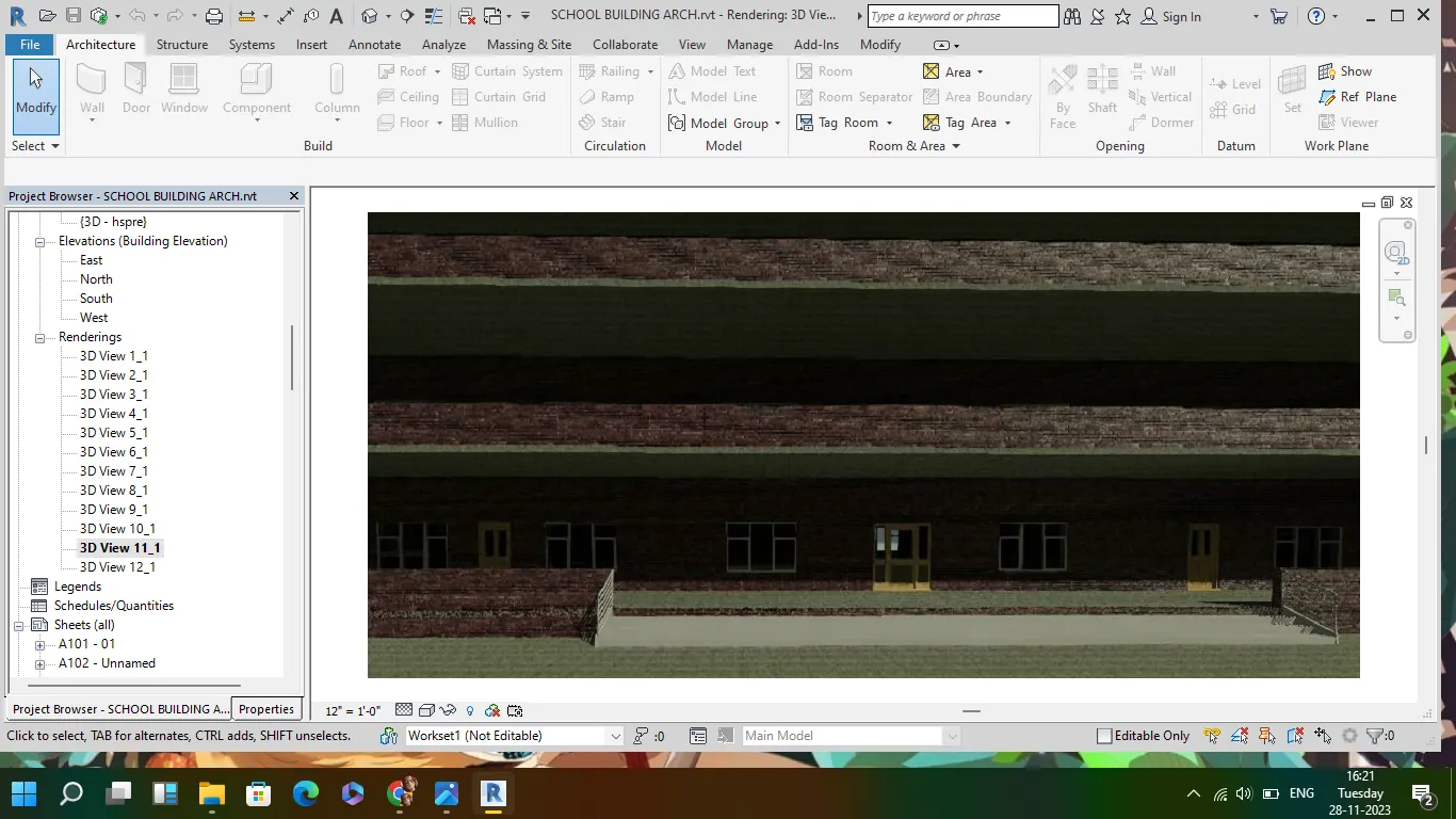
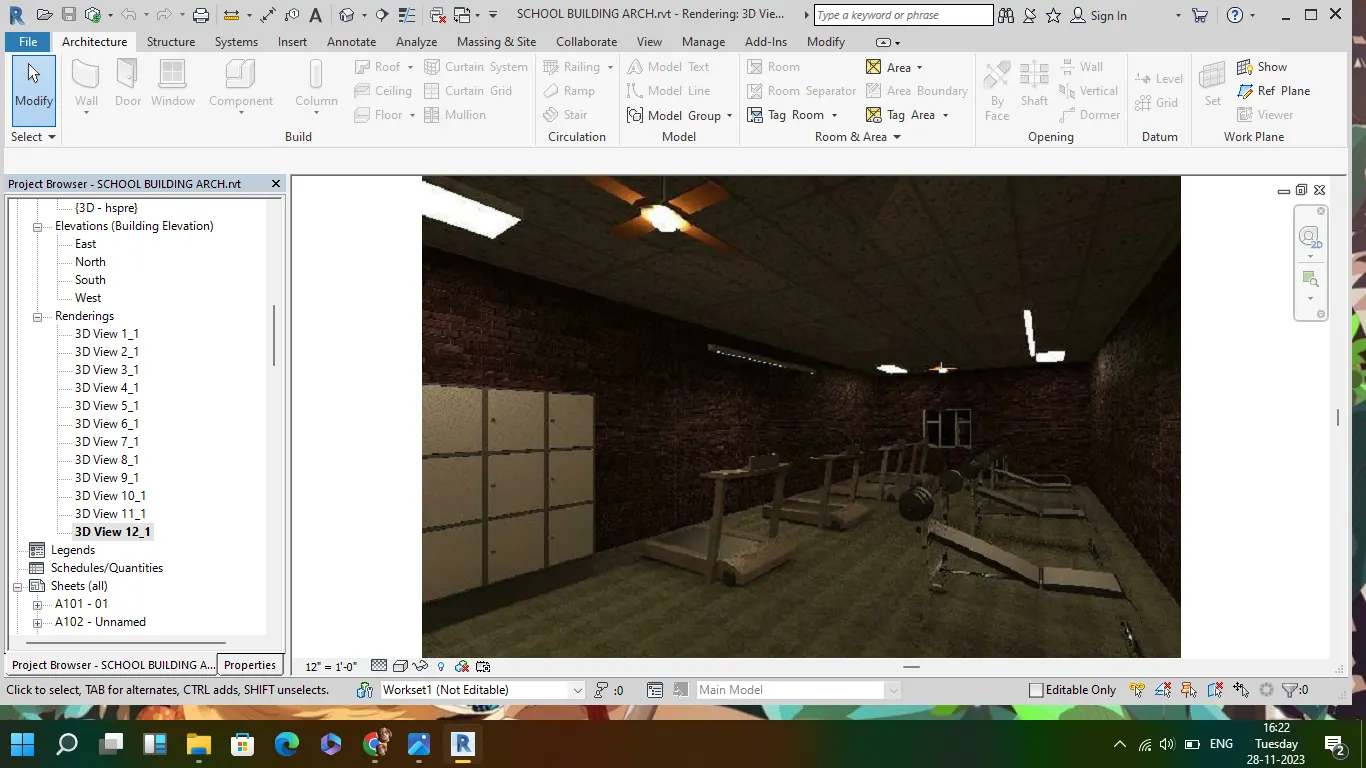
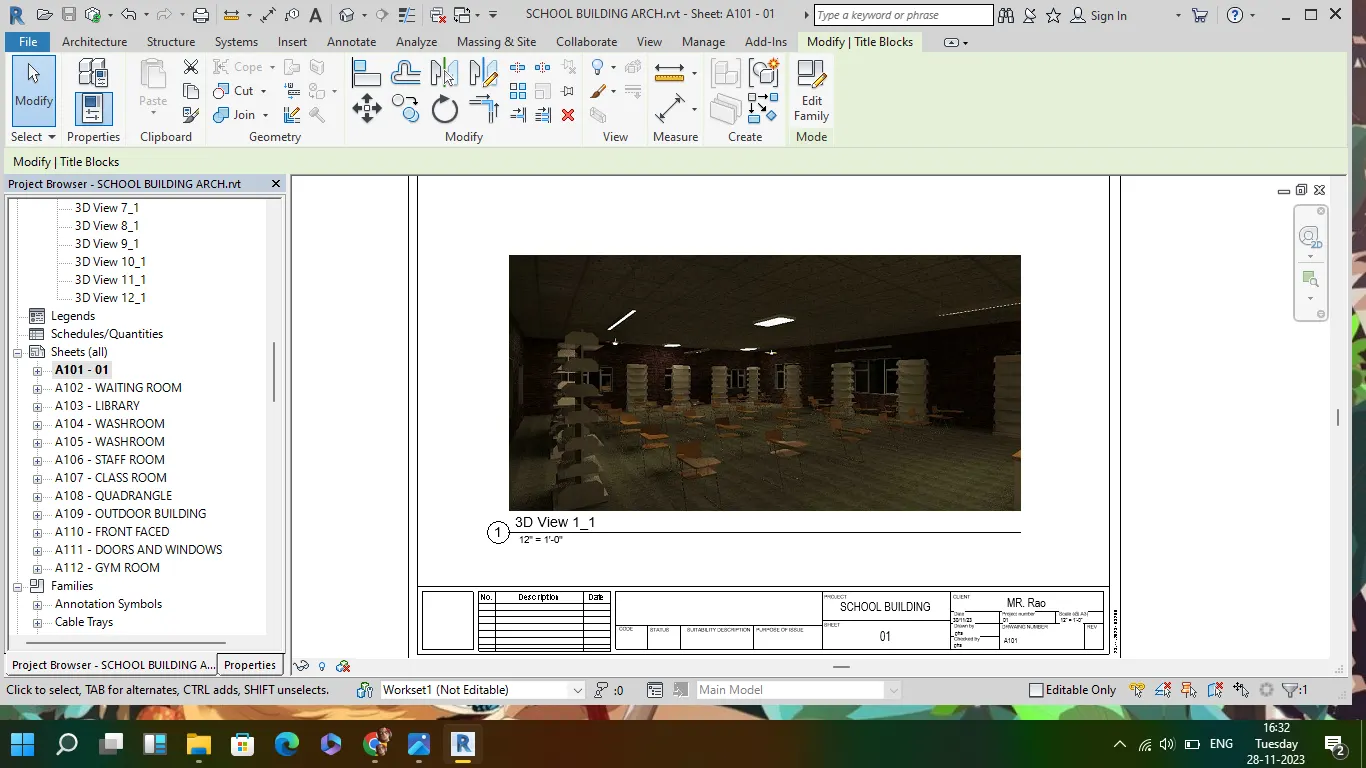
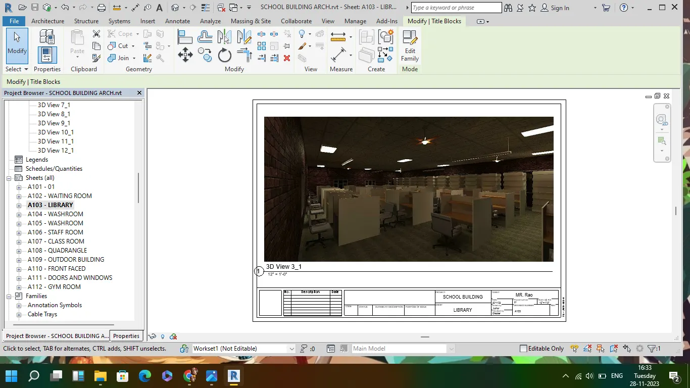
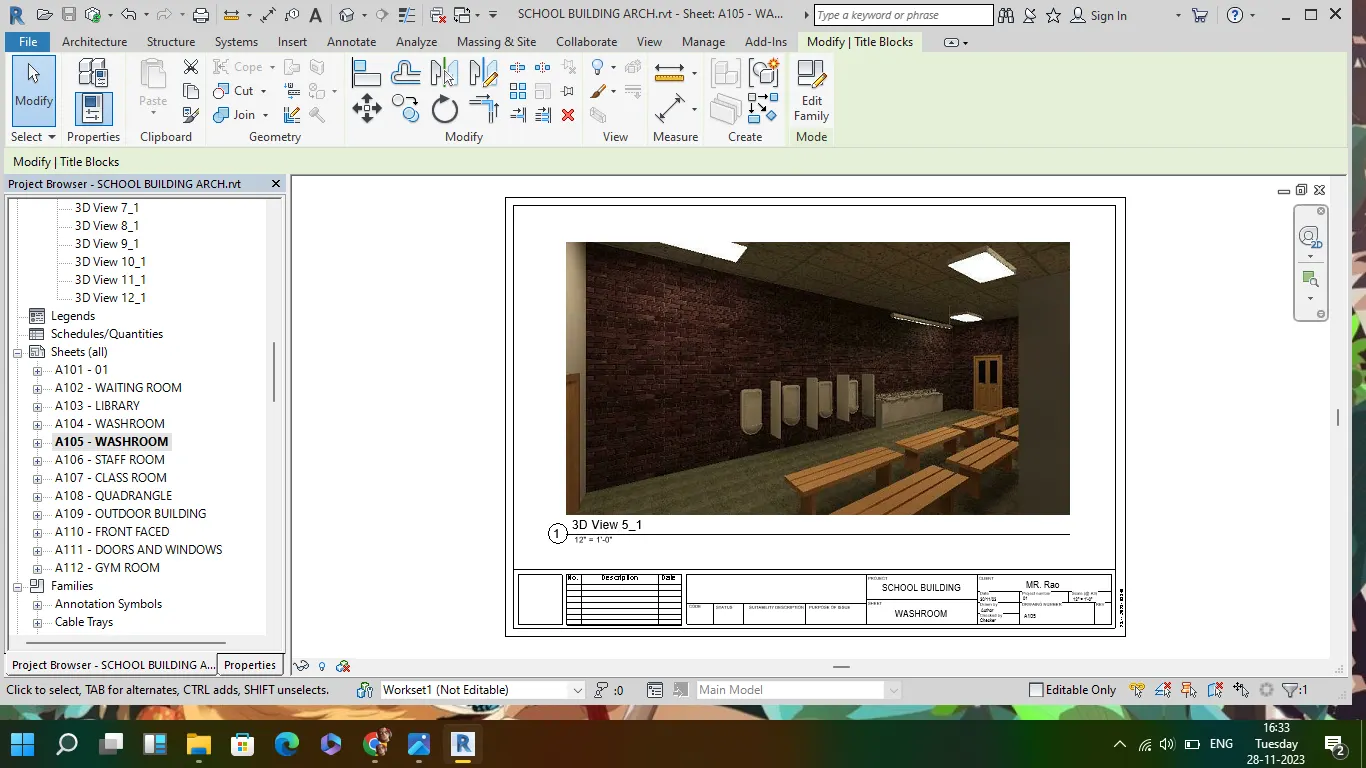
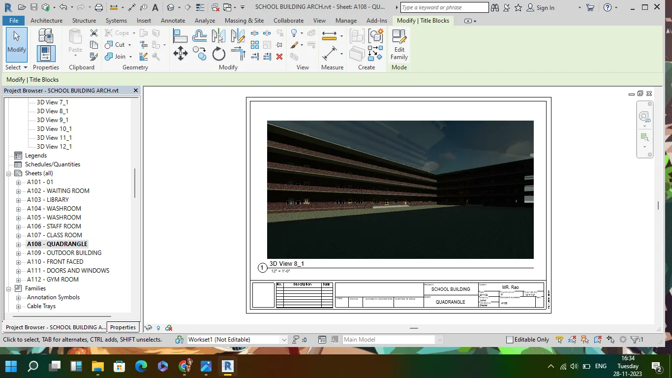
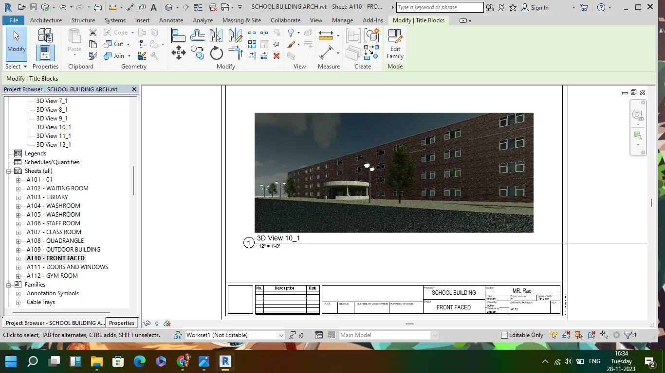
Aim : Using the Rendering settings, Render images of the 3D model produced and include the rendered images to the drawing sheets
a. Rendering from interior rooms
b. Rendering from out showing topographic features
c. Rendering through structural framing
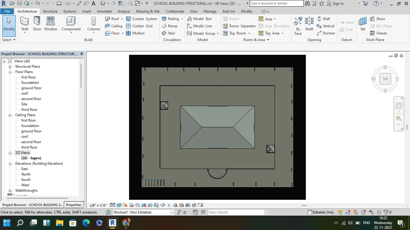
3D views
7 Aim:
To print the set of drawing sheets created and submit the drawings from the architecture and structure model
- press control + P
- a printing dialog box is seen on screen, select the view and sheets
- select set and press okay, select sheet template or image wanted
- save it as a pdf file to take printout later
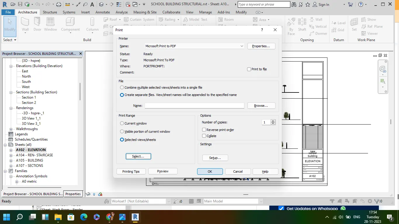
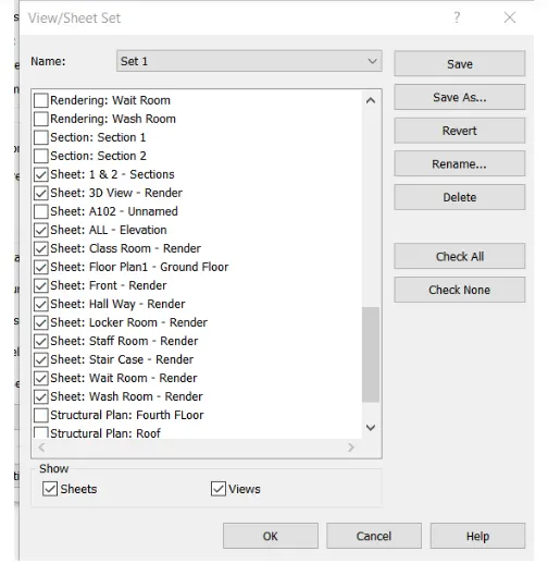
selecting sheets to to be printed and take printout