Creating Architectural and Structural model with 3D rendering using REVIT
1) Select the type of structure you want to build from one of the three below:
a. Multi-Unit Residential Apartment
b. Office Buildings
c. School
Ans:
Office Building
2) Assume reasonable assumptions for geographic and location details for your project modeling. Based on assumptions and type of structure selected identify the modeling requirements from NBC
Ans:
- my project is in plain area.
- it is in commercial area.
- road width infront of my structure is 60f
- area measures should be under NBC rules
- the height of building should not exceed 1.5 times the width of the road width
- fire safety is also provided as per NBC
3) Using the structural model, include the following components based on the type of structure selected
a. Foundation – Isolated / Wall/Matt Foundatio
b. Column
c. Beams Connected to Column
d. Roof Framing/ Trus
e. Floor / Deck
f. Floor Openings for Elevators and Stairs
PROCEDURE:
open revit and make horizontal and vertical grids at spacing of 20' as per ncb.
go to the elevation and increase the number of levels upto roof and change their names.

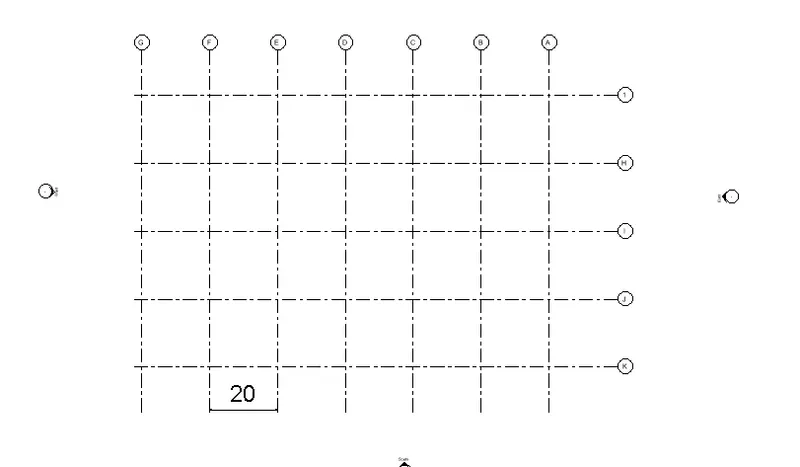
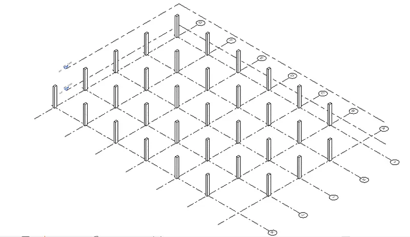
select column from ribbon andplace the column at intersection of grids.
place another column on the grid intersection from to all floors.
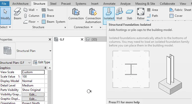
now select the isolated option from the ribben and connect this beam to different column.
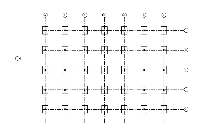
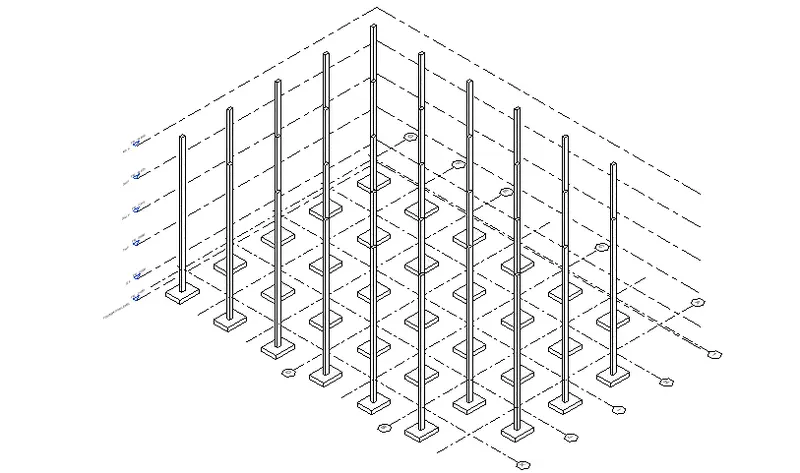
now select the column option from the ribben and connect this beam to different column.
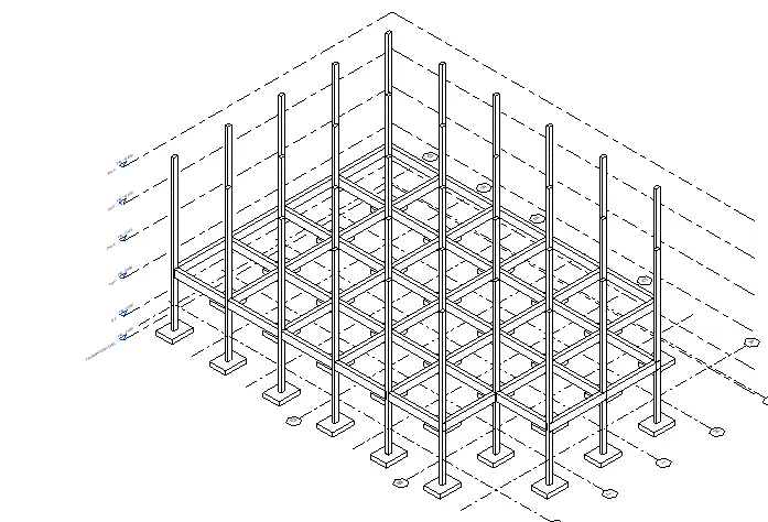
select the entire figure option and go to the copy option and assign them to ground floor to third floor.
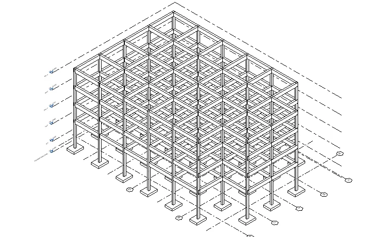
now go to ther oof option and change the view to ground floor and select point and make a loop.
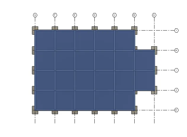
select the roof , go to the copy and select paste option align to select levels and select the different levels.
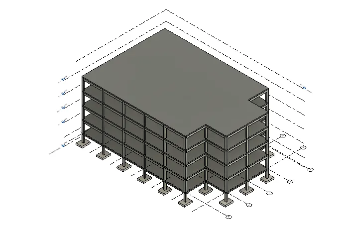
from the properties option change the colour and material of roof and walls.
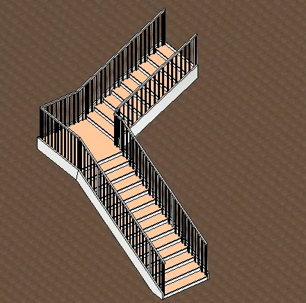
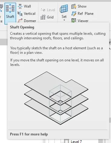
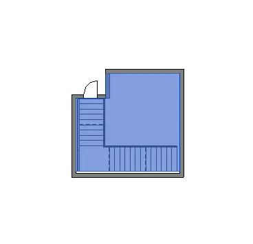
draw a shaft and make stairs in that as shown in figure ,copy and place to different floor levels.
Result:
The structural model of my choice including all the components to elevate the structure is created.
4) Using the architectural model, include the following components based on the type of structure selected
a. Wall Layout with appropriate material and finishing
b. Exterior façade with fancy finish
c. Interior partition walls to size rooms
d. Components to add details to a room ( Desk, Chair, Lighting, Plumbing fixtures)
e. Add components such as stairs Elevators
f. Have at-least one side of the building with curtain walls and glass panels
g. Include interior and exterior lighting fixtures
h. Place proper topographic components from outside ( Trees, Parking, Plants) to add details to the model
Procedure:
Firstly open the architectural file that we have inserted the structural.
Select the copy monitor and copy all the grids from the structural file.
Draw the levels as required.
copy all to the rest of the floors.
Draw the exterior walls also by keeping in the mind that one of the side must be a glass wall.
Draw the interior wall with the required dimensions.
Draw a flat accordingly with the desired dimensions and place the components.
For placing the components select the insert tab and load the families and then we will find the loaded components in the project browsers such as doors,windows,toiletries,beds,tables,chairs,sofa,ect...
place the celling with the help of pick lines option.
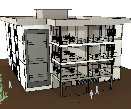
Result: The architectural model of my choice including all the components to elevate the structure is created.
5) Provide a set of drawings in an architectural and structural model to list the following details with categories and appropriate sheet templates included
a. Floor Plans with Annotations
b. Elevations
c. Sections
Procedure:
Select the view tab and select sheets and load it from the family.
Click on the sheet names and address and change them accordingly
insert the, you have previouly taken of all the section, plan and elevation views
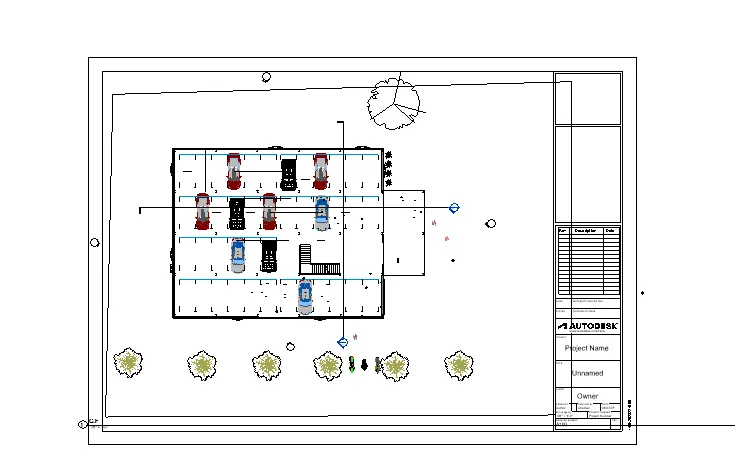
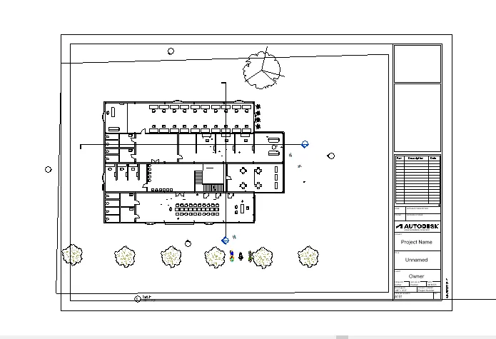
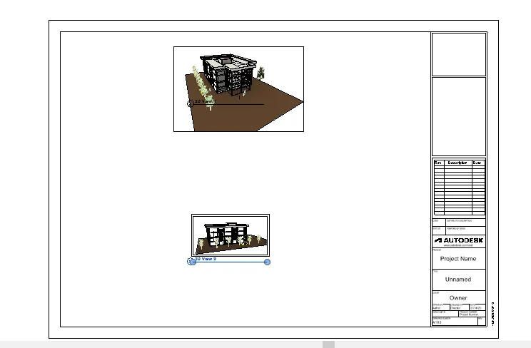
Result: The rendered images are put into drawing sheets.
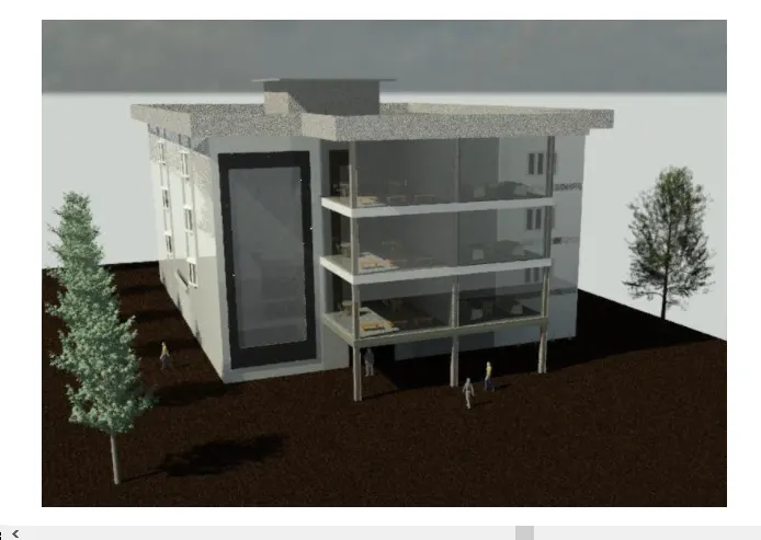
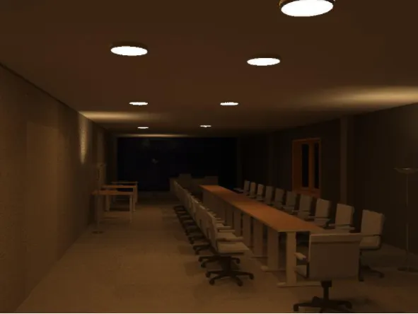
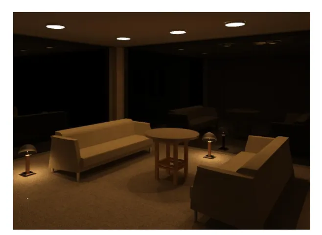
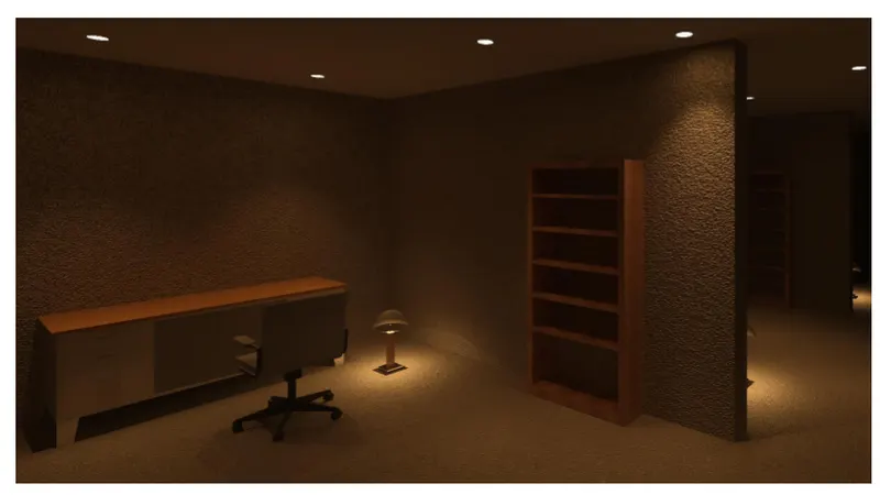
6) Using the Rendering settings, Render images of the 3D model produced and include the rendered images to the drawing sheets
a. Rendering from interior rooms
b. Rendering from out showing topographic features
c. Rendering through structural framing
Procedure:
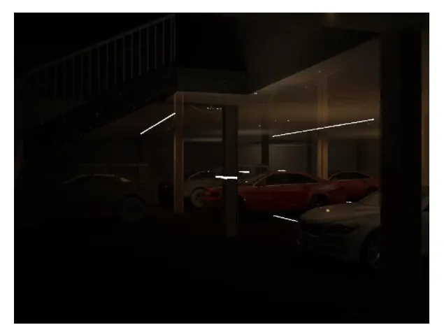
Select the images of the interior,exterior and structural framing and select the render option for rendering.
After clicking on render option a dialog box appers and in the we need to set the settings such as the the region, artificial settings,lighting,cloud visibility etc.
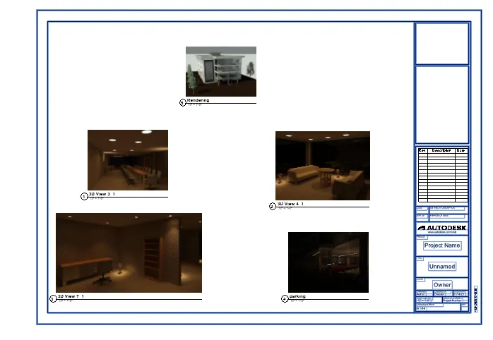
7) Print the set of drawing sheets created and submit the drawings from the architecture and structure model
Procedure:
- Select the views and click print option .
- Adjust the settings accordingly and print the drawing sheets .
RESULT:
Since i am not having a printer installed at my home i'm just pasteing the images of drawing sheets here.