Creating Architectural and Structural model with 3D rendering using REVIT
Aim of the project: To draw the given plan along with the given sections with appropriate dimensions.
The drawing in the project is done with help of AUTOCAD software.
Procedure:
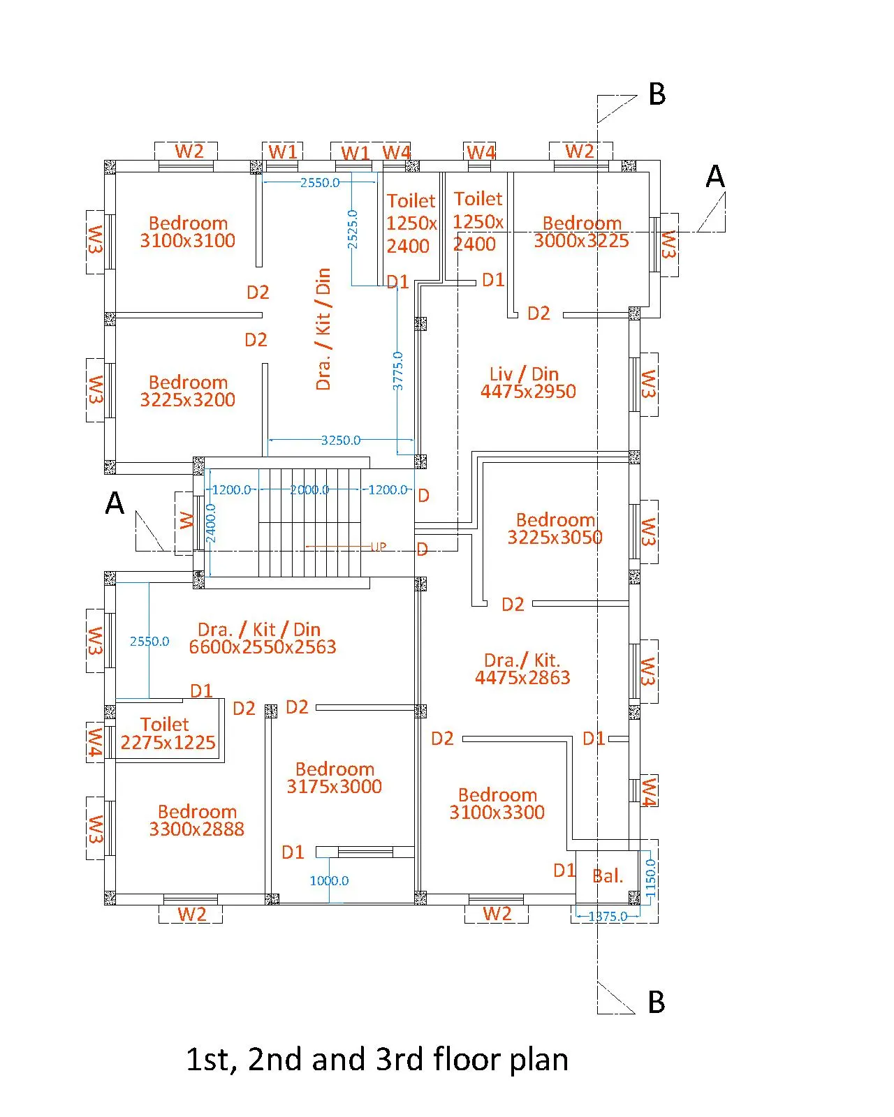
Step 1: The units of the drawing sheet is set to Engineering precision.
Step 2: Construction line in horizontal and vertical direction are drawn using the command ‘XL- h’ and ‘XL-v’
Step 3: A corner is created by trimming the bottom and left side of the construction line using the trim command: ‘TRIM’
Step 4: In order to create outer wall of 250mm thick, the offset command is used with a distance of 250mm. The offset is created in both horizontal and vertical direction.
Step 5: Another offset of 125mm is created for internal walls.
Step 6: Then an offset of the required room size (for example 3100mm or 3300mm) is created from the innermost line in the vertical direction. An offset of 125mm is created for the inner wall. The extra lines are trimmed off using the trim command.
Step 7: Similarly offset lines are created based on the room size and dimensions mentioned in the plan.
Step 8: In order to create the Section mentioned, construction lines are drawn as projections for the appropriate dimensions of the room size and locations of windows and doors.
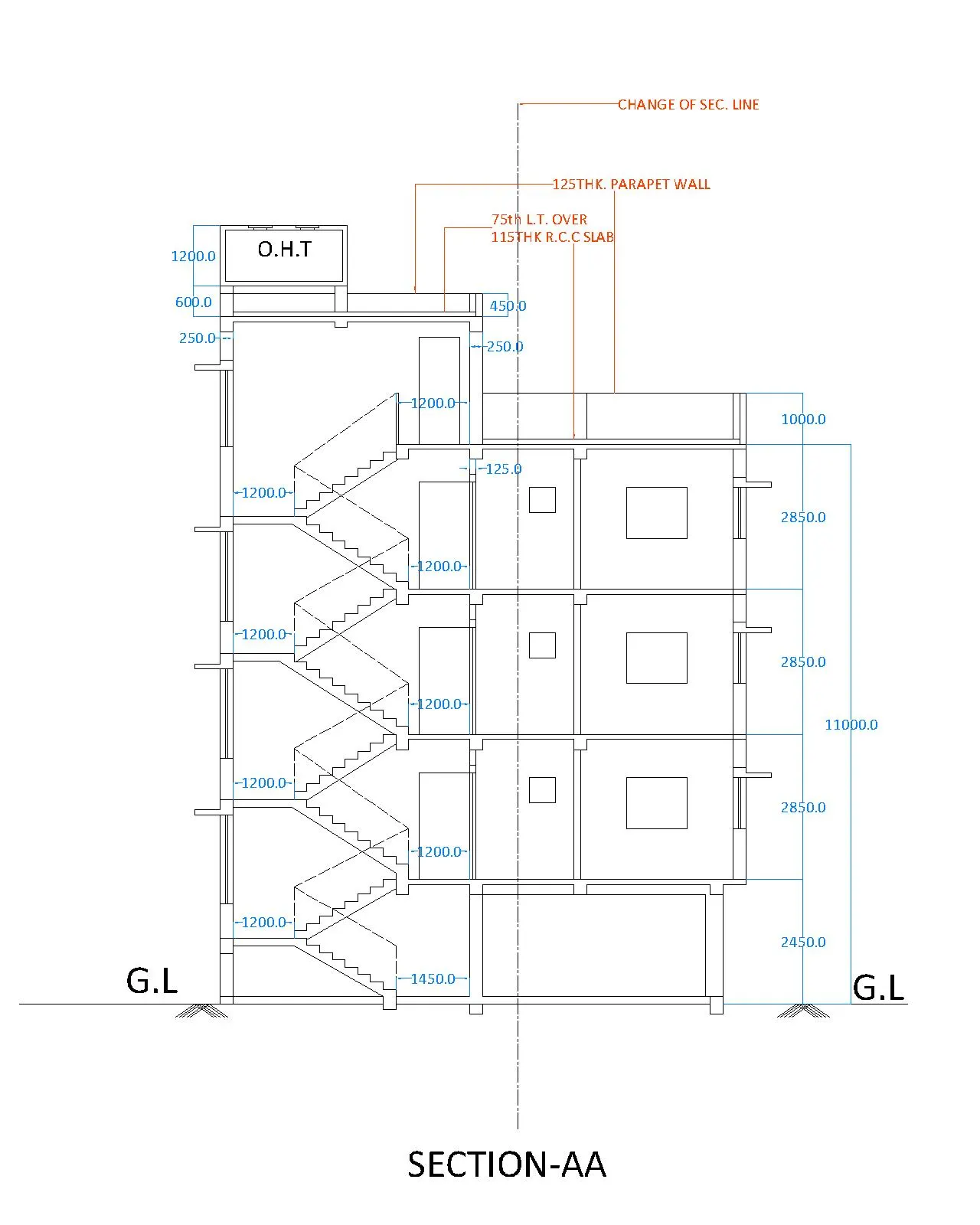
Step 9: Once the projections from the plan is drawn for the location of the required section, the floors are created with offset command with the appropriate floor height mentioned in the section.
Step 10: The stairs are drwan in accordance with the riser and thread dimensions mentioned in the drawing. For G.F level, the riser and thread are 143.75mm and 250mm respectively. And for the above floors the riser and thread are 158.33 and 250mm respectively. Support beams are provided for the staircase at floor level and at landing level.
Step 11: The parapet wall and the over head tank are drawn as per the dimensions mentioned in the drawing with the help of offset command and trim command where-ever required.
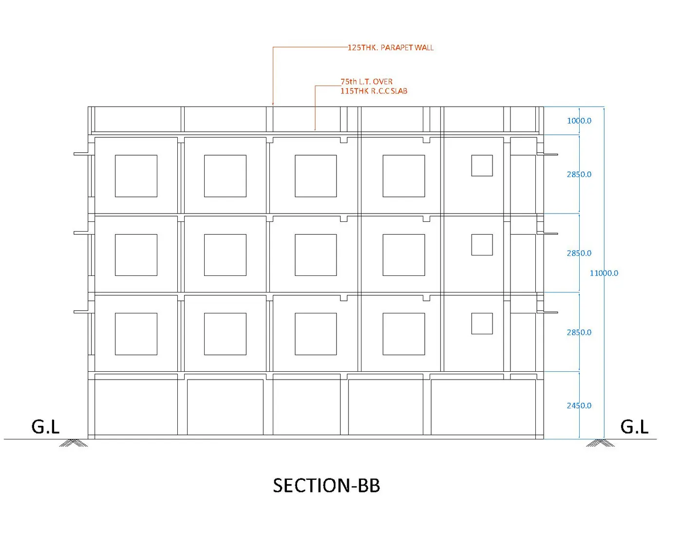 Step 12: Similarly projections are created for Section BB to locate the columns, beams and so on.
Step 13: With the obtained projections, the floors are drawn with appropriate floor height as mentioned in the drawing.
Results Obtained:
The drawing presented in this project contains plan and two sections of the three storey residential building. The dimensions of the rooms are mentioned with different layer options. The section lines are mentioned in the plan for better understanding of the plan as well as the section.