Creating Architectural and Structural model with 3D rendering using REVIT
1) Select the type of structure you want to build from one of the three below:
a. Multi-Unit Residential Apartment
b. Office Buildings
c. School
ANS :
The type of structure I have selected is Multi Unit Residential Apartment for my project.
2) Assume reasonable assumptions for geographic and location details for your project modeling. Based on assumptions and type of structure selected identify the modeling requirements from NBC.
ANS :
ASSUMPTIONS :
The assumptions made in the project are as below :
- Type of Structure - Multi Unit Residential Apartment
- No. of Storey - G+3
- Location of the structure - Chennai, Plain Terrain
NBC REQUIREMENTS :
The following are the requirements made in the project as per NBC :
HEIGHT LIMITATIONS :
- As per NBC 2005, Clause C-2.5, the maximum height of the building shall not exceed 1.5 times the width of the road
- Since my model is constructed in the residential area, the width of the road is 10m.
- The Height of the building = 12m which satisfies NBC guidelines.
AREA LIMITATIONS :
- As per NBC C-2.3.1, the minimum plot size with ground coverage not exceeding 75% shall not be less than 40 sq.m in small and medium town and not less than 30 sq.m in metropolitan area.
- The plot size of my model is 22x22 = 484 sq.m which satisfies NBC guidelines.
ROOM SIZING :
- In a house of double room, first room shall not be less than 9 sq.m with minimum width of 2.5m and second room shall not be less than 6.5 sq.m with a minimum width of 2.1m provided the total area of both the rooms is not less than 15.5 sq.m
- In my model, total number of rooms is two and the total area of the rooms is greater than the value specified in the code.
WALL HEIGHT :
According to NBC 2005, Clause F-3.4, the minimum height of rooms and spaces should be :
- Habitable room – 2.75m
- Kitchen – 2.6m
- Bath / Water closet – 2.2m
- Corridors – 2.1m
- In case of sloping roof the average height of roofs for habitable rooms shall be 2.75m and the minimum height at eaves shall be 2.1m
- In my model all the walls have a height of 3m which is greater than the minimum wall height specified in the code.
OPEN SPACE :
- Front open space - Every building should have a front yard of minimum width of 3m
- Rear open space - Every residential building shall have a yard of an average width of 4.5m
- In my model, all the open space around the building is taken as 5m.
FAR VALUE :
- Floor Area Ratio (FAR) is the ratio of total floor area to the total plot area.
- In my mode, the plot size is taken as 22x22 = 484 sq.m and individual floor area is 144 sq.m.
- Hence the FAR ratio is calculated as 1.19 which is within the NBC guidelines.
3) Using the structural model, include the following components based on the type of structure selected
a. Foundation – Isolated / Wall/Matt Foundation
b. Columns
c. Beams Connected to Columns
d. Roof Framing/ Truss
e. Floor / Decks
f. Floor Openings for Elevators and Stairs
AIM :
To include the following components based on the type of structure selected using the Structural Model.
a. Foundation – Isolated / Wall/Matt Foundation
b. Columns
c. Beams Connected to Columns
d. Roof Framing/ Truss
e. Floor / Decks
f. Floor Openings for Elevators and Stairs
PROCEDURE :
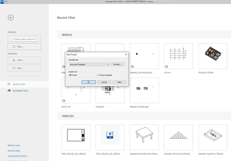
STEP 1: Open Revit Software. Create New project -> Structural Template. Click OK.
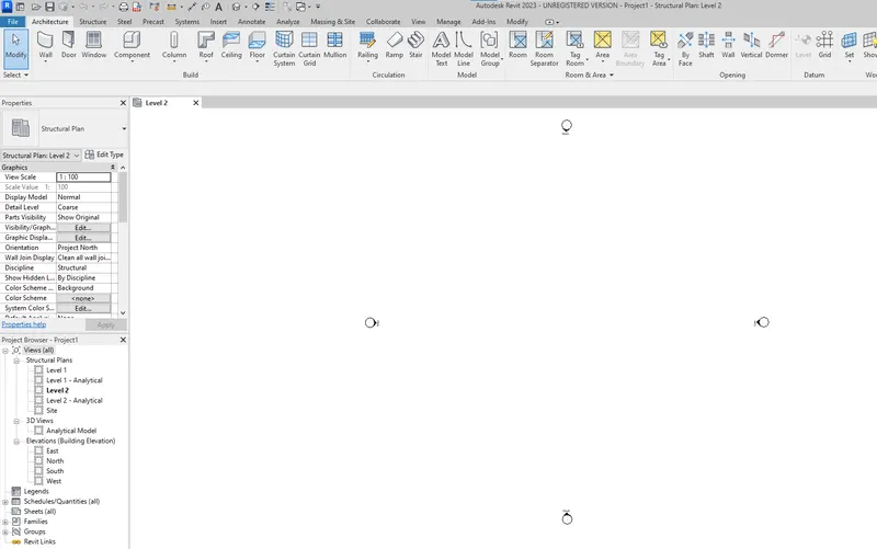
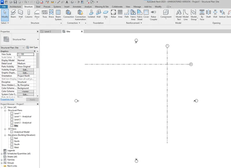
STEP 2 : After opening the Structural template, draw one horizontal and vertical grid lines as below.
STEP 3 : To set the coordinates, click on Manage -> Coordinates icon -> Specify Coordinates at Point.
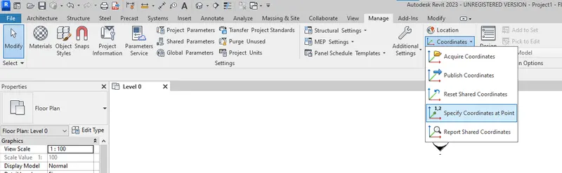
STEP 4 : Select the grid line 1. A dialog box appears, enter the value as 0 in the East/West direction. Click OK.
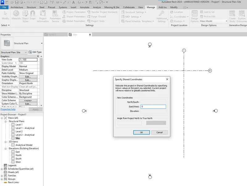
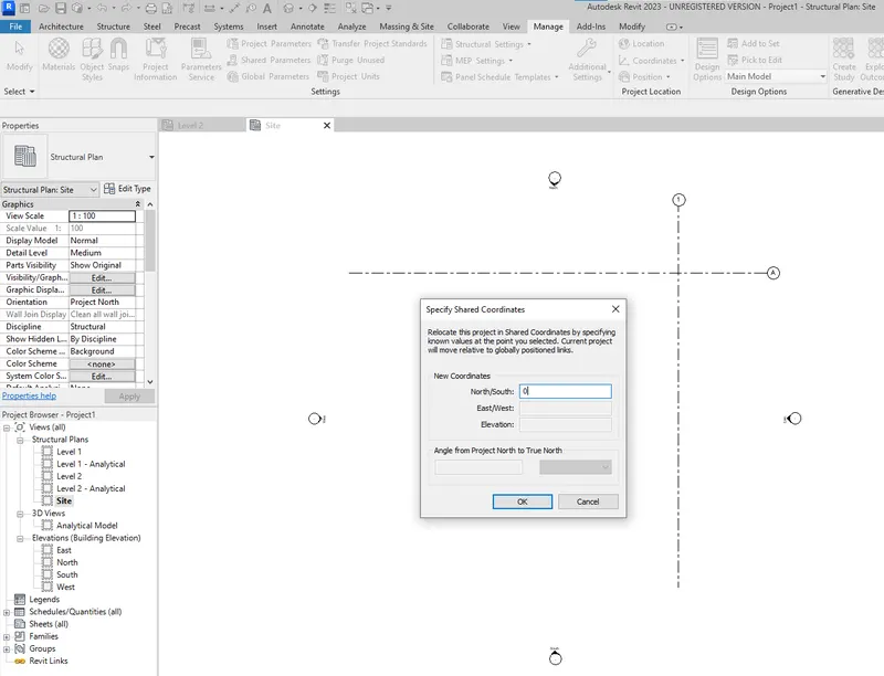
STEP 5 : To set the coordinates for grid A, click on Manage -> Coordinates icon -> Specify Coordinates at Point.
Select the grid line A. A dialog box appears, enter the value as 0 in the North/South direction. Click OK.
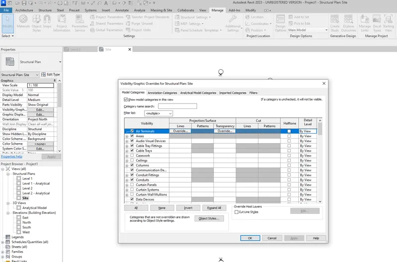
STEP 6 : To set the project base point, type the command 'VG'. Visibility Graphic dialog box appears.
STEP 7 : Expand the Site option from the dialog box and check the Project Base Point option. Click OK.
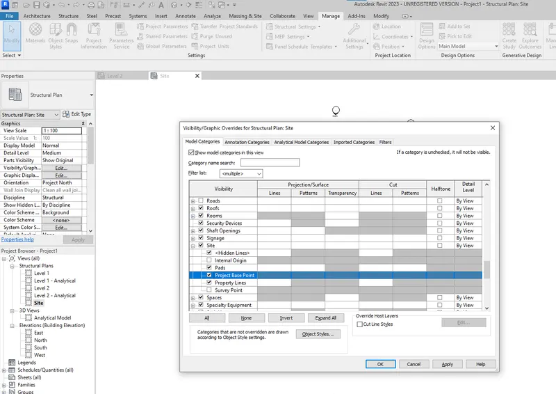
STEP 8 : After checking on the Project Base Point, the project base point icon appears.
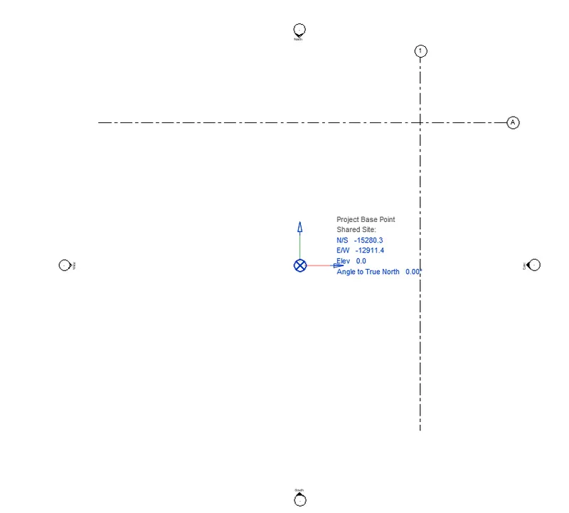
STEP 9 : Now move and place the icon in the intersection point of the two grids.
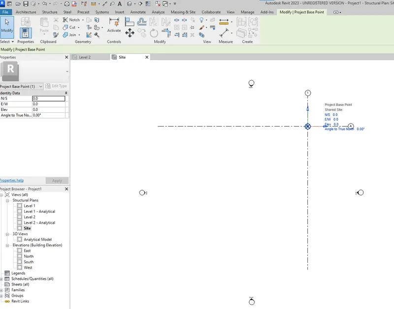
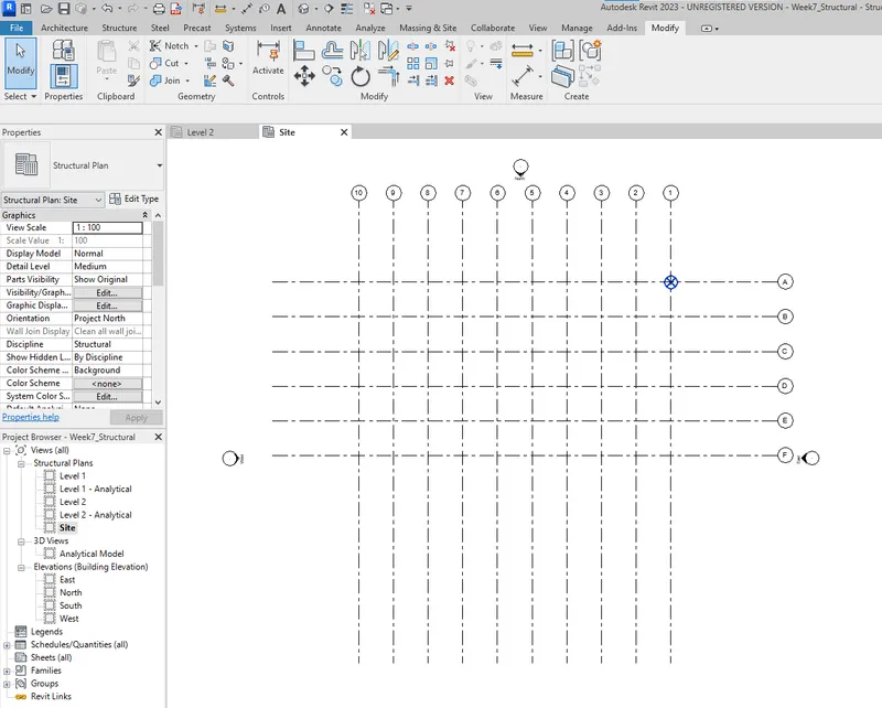
STEP 10 : Create the longitudinal grid and transverse grid lines by clicking Structure -> Grids, Enter the offset value by selecting pick line option.

STEP 11 : To create Levels, click on elevation tab from the project browser which is in the left panel of the layout ans select any one direction. Level icon is now enabled.

STEP 12 : Now select Level icon and select the pick lines icon. Enter the level values in the offset tab and create the levels. Rename the level names according to our requirements.

STEP 13 : Levels are created as per the requirements.
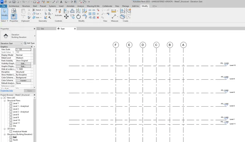
STEP 14 : Rename the level names according to our requirements.
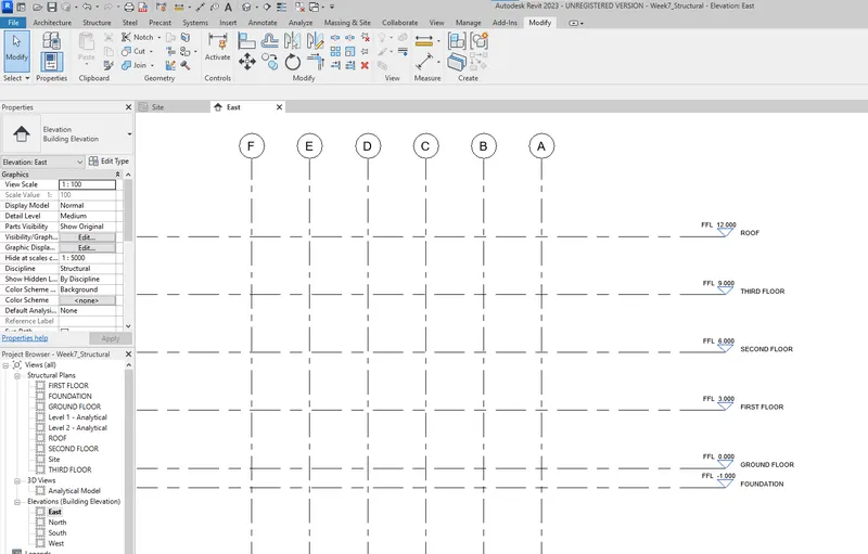
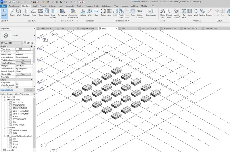
STEP 15 : To place the foundation, Go to foundation plan and then Click Structure -> Isolated.
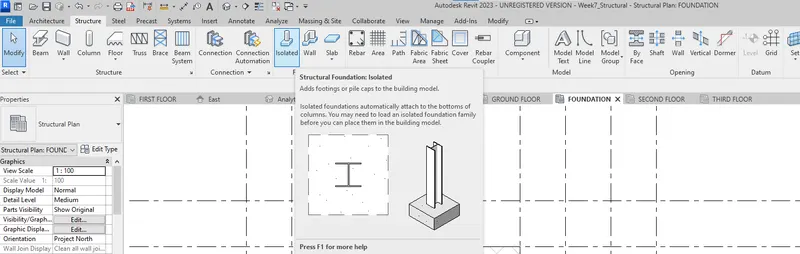
STEP 16 : The ribbon tab changes, now click on At grids to place the footings at the intersection of the grids.
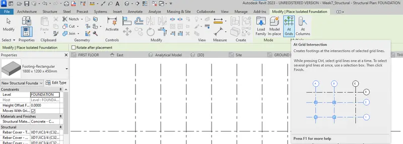
STEP 17 : Select the grids to place the footings at the desired locations. Then click on Finish icon.
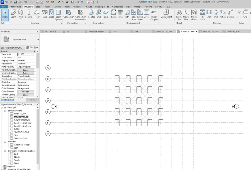
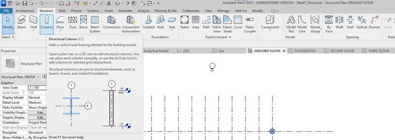
STEP 18 : To place the column, go to the Ground level plan and then Click Structure -> Column
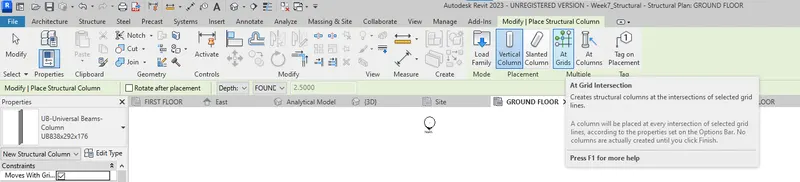
STEP 19 : The ribbon tab changes, Select Vertical column icon and now click on At grids to place the Columns at the intersection of the grids.
STEP 20: Select the grids to place the columns at the desired locations. Then click on Finish icon.
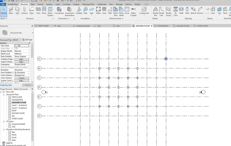
STEP 21 : To extend the columns till the Third floor, Go to ground floor plan, select all the columns.
Go to Property box -> Top Level as Third Floor -> Base Offset as 0. Click Apply.
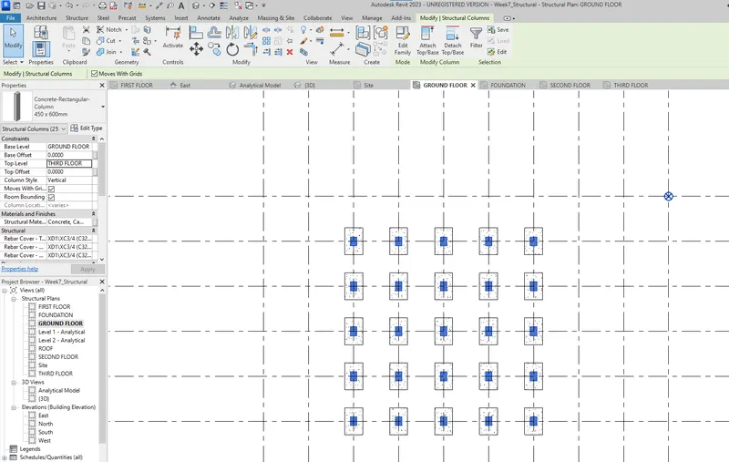
STEP 22: Columns are extended till the third floor level as shown.
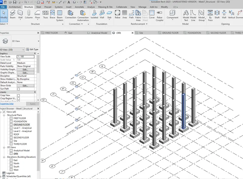
STEP 23: To draw the Beam, go to ground floor plan and Click Structure -> Beam

STEP 24: The ribbon tab changes, now select On Grids to place the beams at the desired location.
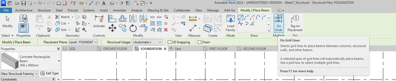
STEP 25: Select the grids at which the beam has to be placed.
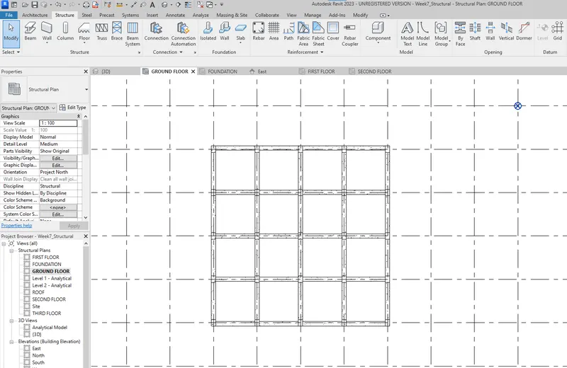
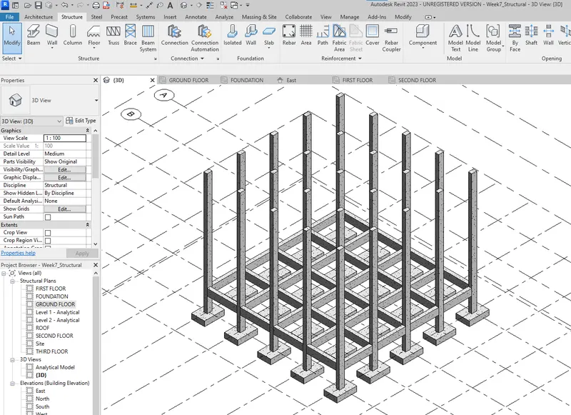
STEP 26: To copy the beams from ground floor to all the floors, select the beams created.
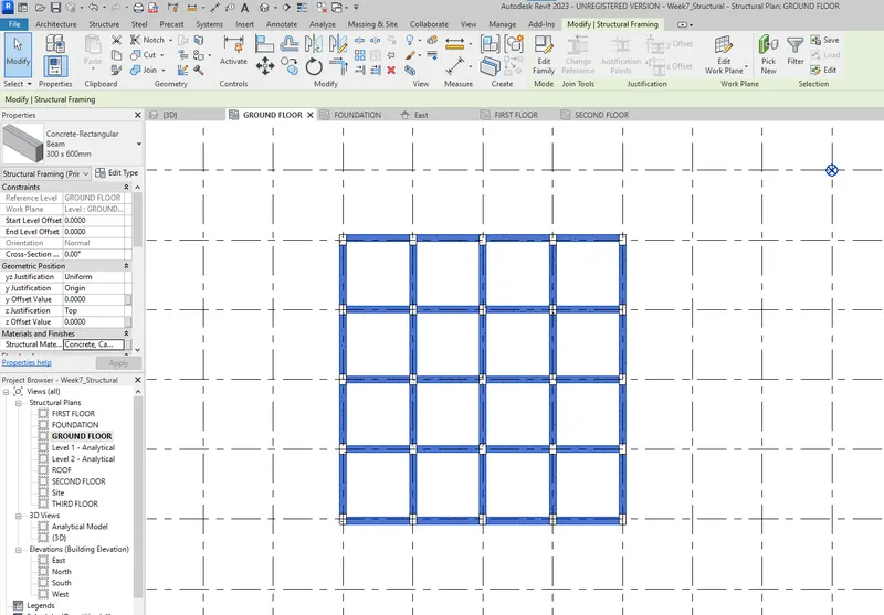
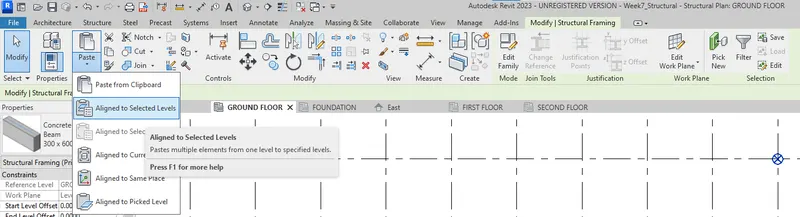
STEP 27: Now click -> Copy icon -> Paste. Now select the option, Aligned to selected levels.
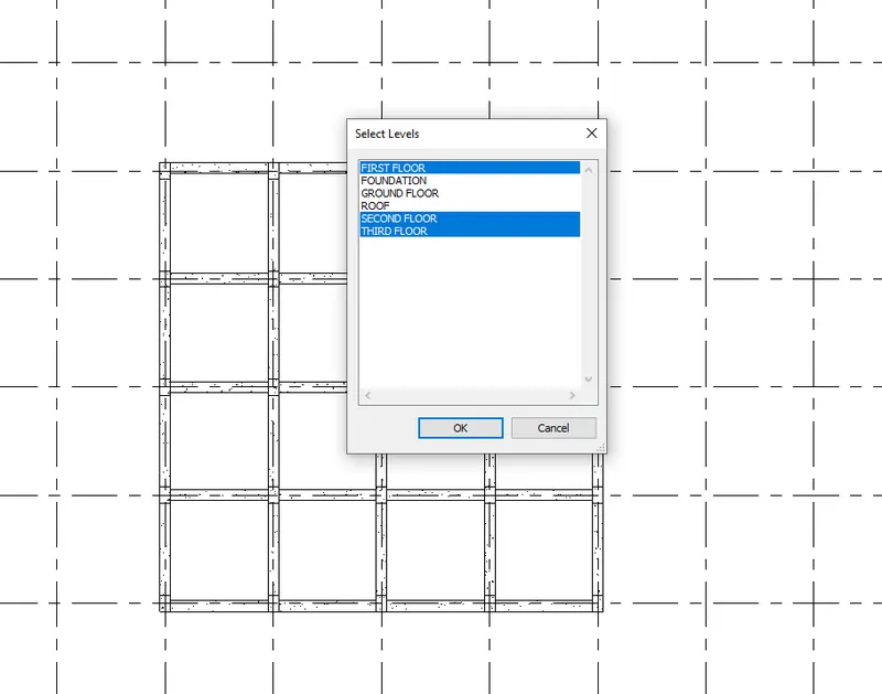
STEP 28: A dialog box opens, select all the levels to which the beams have to copied. Click OK.
STEP 29: Beams are now created in all the selected floors.
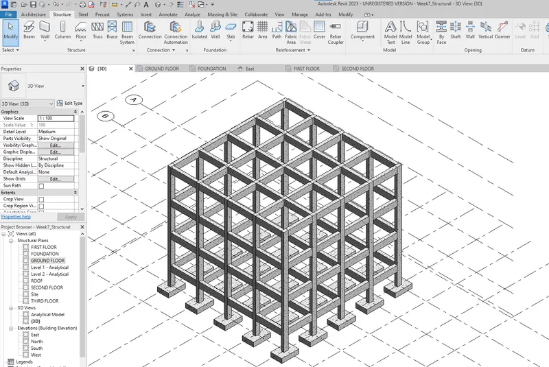
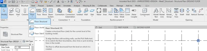
STEP 30: To create floors for the model, Go to Ground floor plan, Click Structure -> Floor -> Floor : Structural
STEP 31: The ribbon tab changes, now draw the floor using the Rectangle icon.

STEP 32: Draw the boundary line using the rectangle tool and then click on Finish Edit Mode icon.
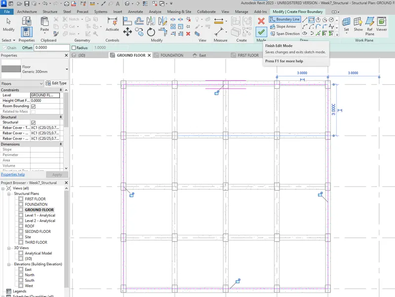
STEP 33: Floor is created in the Ground Floor.
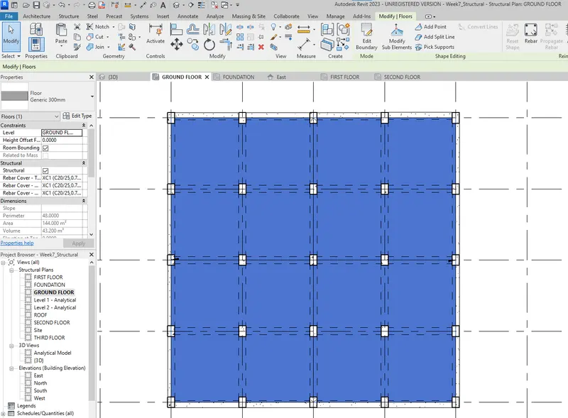
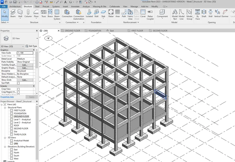
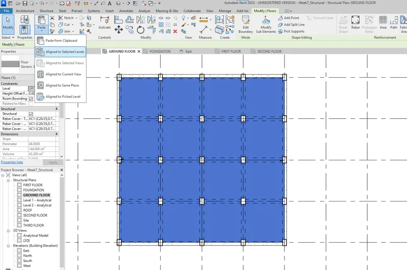
STEP 34: To copy the floor from ground floor to all the levels, select the floor created.
Click on Copy -> Paste -> Aligned to Selected levels.
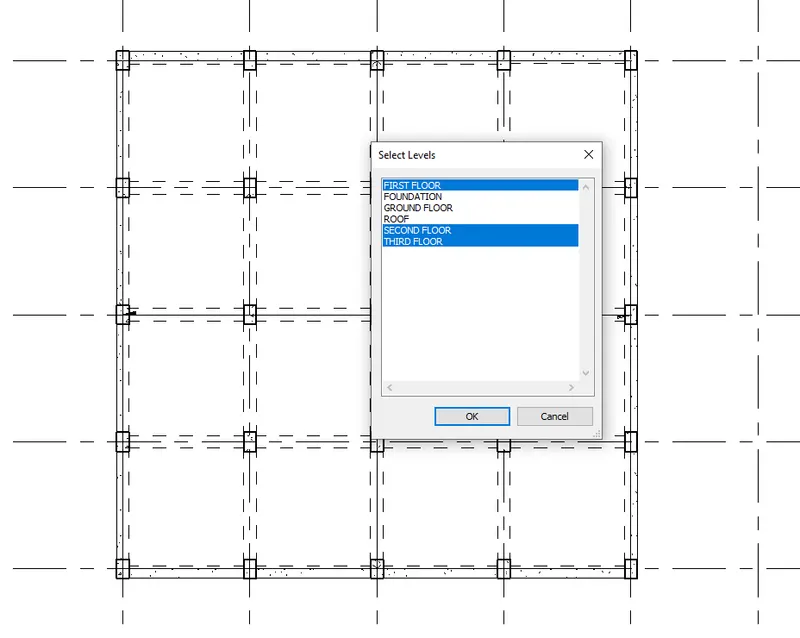
STEP 35: A dialog box opens, select all the levels to which the beams have to copied. Click OK.
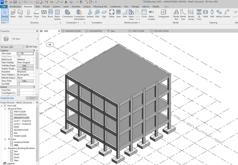
STEP 36: Floors are now created in all the levels.
STEP 37: To create Elevator opening, Click Structure -> Shaft

STEP 38: The ribbon tab changes, now draw the shaft opening the desired place using rectangle toolbar.
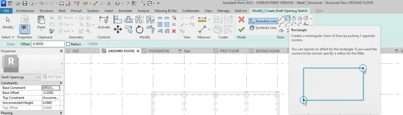
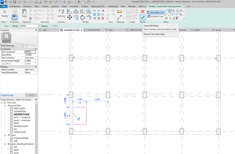
STEP 39: Now draw the opening in the desired place
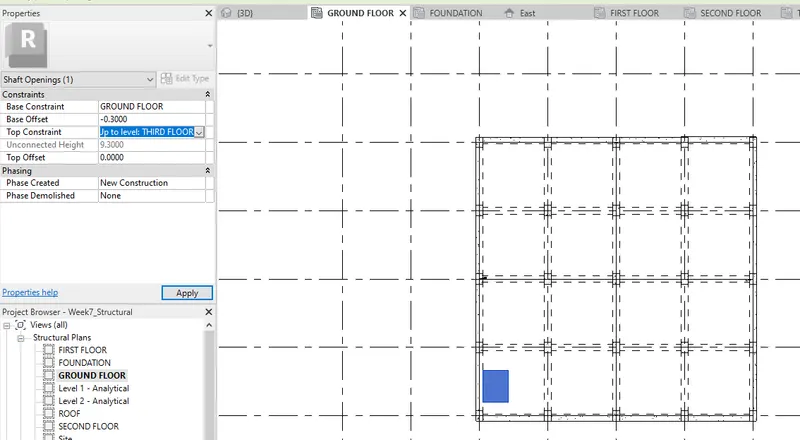
STEP 40: To connect the opening till the third level, Select the shaft opening created, go to Property box, Change the Top Constraint to Third Floor.
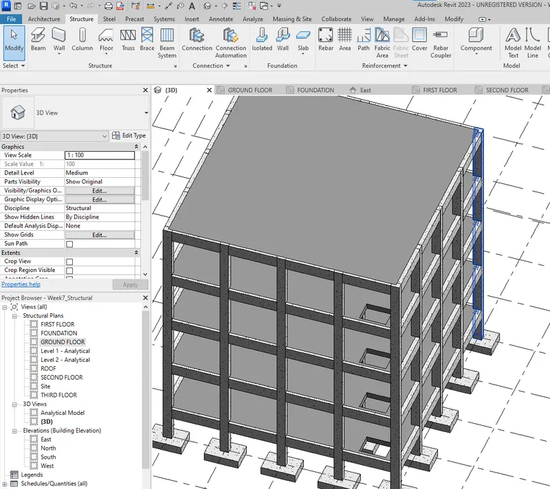
RESULT :
A multi level residential unit is created in Structural Template and all the necessary structural components including Footings, Beams, Columns, Floors, Ceilings and Floor opening for Elevators are added.
4) Using the architectural model, include the following components based on the type of structure selected
a. Wall Layout with appropriate material and finishing
b. Exterior façade with fancy finish
c. Interior partition walls to size rooms
d. Components to add details to a room ( Desk, Chair, Lighting, Plumbing fixtures)
e. Add components such as stairs Elevators
f. Have at-least one side of the building with curtain walls and glass panels
g. Include interior and exterior lighting fixtures
h. Place proper topographic components from outside ( Trees, Parking, Plants) to add details to the model
AIM :
To include the following components in Architectural Model based on the type of structure created.
a. Wall Layout with appropriate material and finishing
b. Exterior façade with fancy finish
c. Interior partition walls to size rooms
d. Components to add details to a room ( Desk, Chair, Lighting, Plumbing fixtures)
e. Add components such as stairs Elevators
f. Have at-least one side of the building with curtain walls and glass panels
g. Include interior and exterior lighting fixtures
h. Place proper topographic components from outside ( Trees, Parking, Plants) to add details to the model
PROCEDURE :
STEP 1 : Open the Architectural Model, link the Structural Model in the architectural model by Insert -> Link Revit.

STEP 2 : Go to Collaborate -> Copy/Monitor, to copy the elements from Structural template to Architectural template.

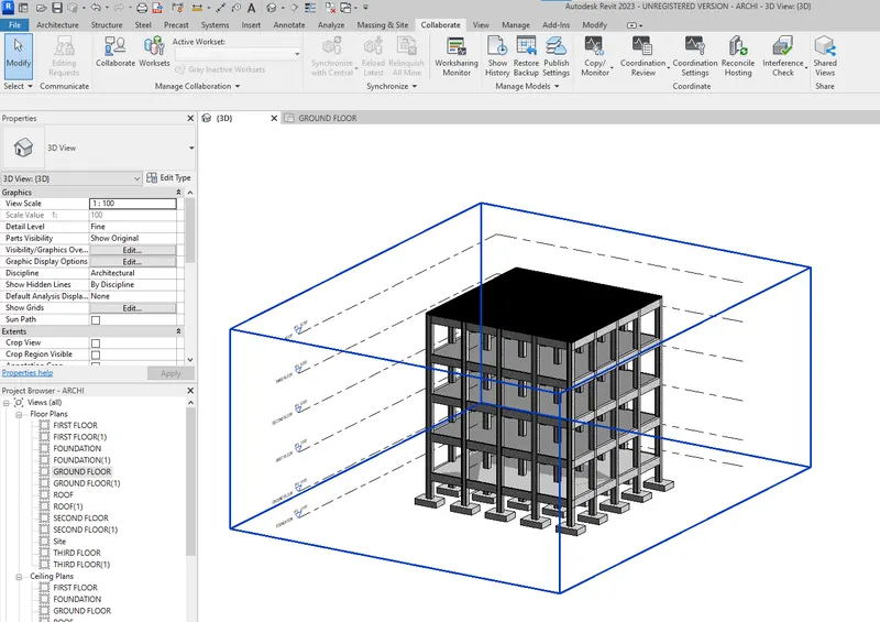
STEP 3 : Structural model is now linked to the architectural template.
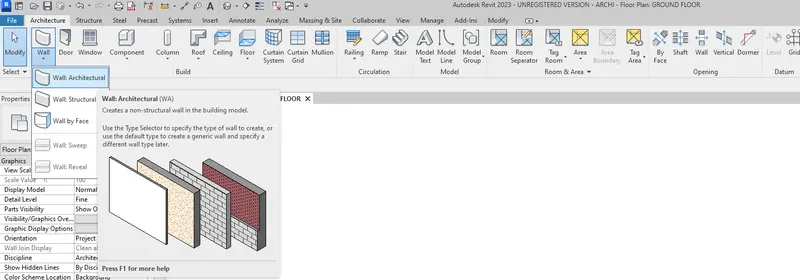
STEP 4 : To create walls, Go to Architecture -> Wall -> Wall:Architectural
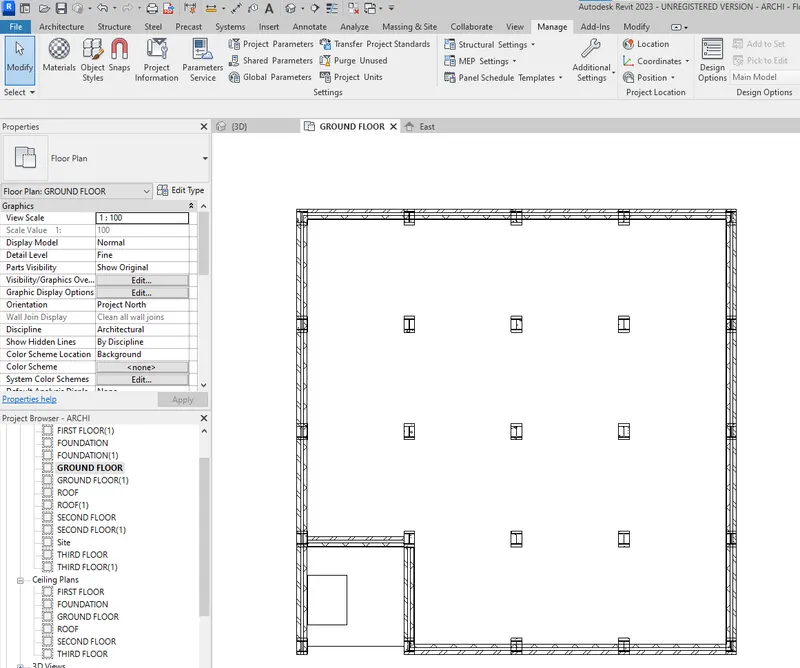
STEP 5 : The ribbon tab changes, now draw the walls at the desired location by using line tool.

STEP 6 : Walls are now created in the ground floor.
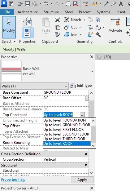
STEP 7 : To extend the walls to the other levels, from the properties box, Clicke Top Constraint -> Up to Level : Roof.
STEP 8 : Walls are now created till the Roof.
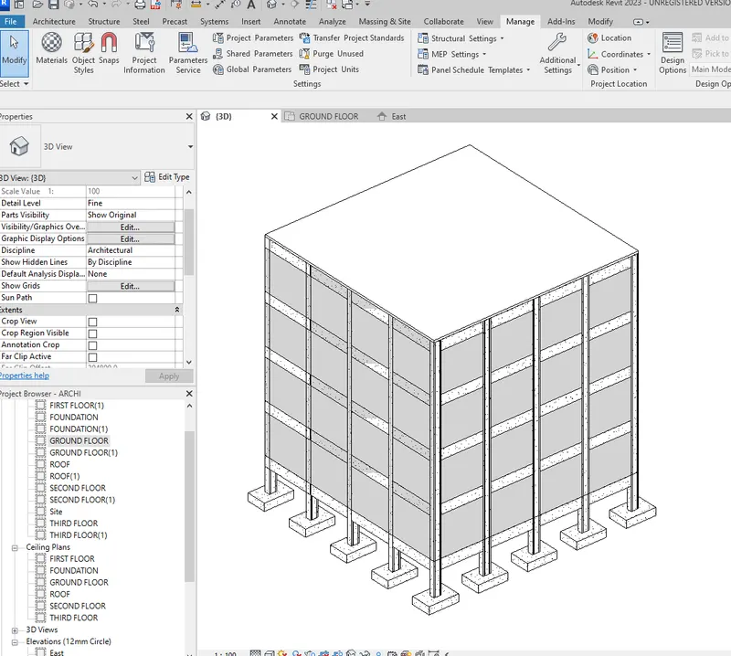
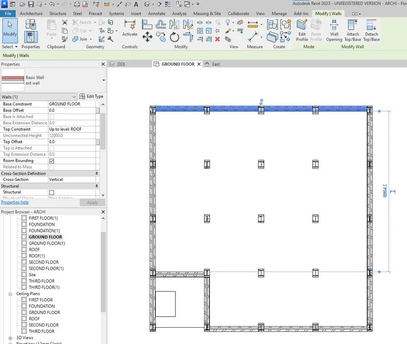
STEP 9 : To change the material and finishing of the wall, select the wall and click on the Edit type tab from the Property box.
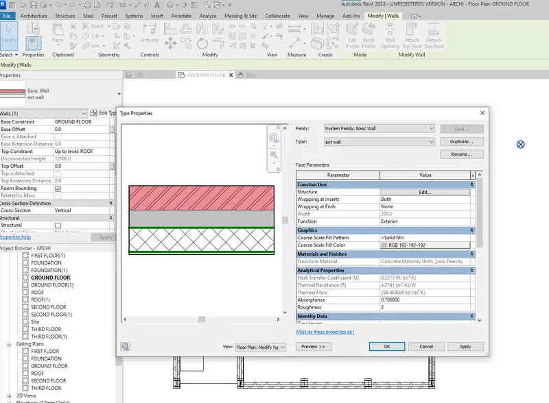
STEP 10 : A dialog box appears, click on the Edit option from the Structure tab.
STEP 11 : From the dialog box, select the appropriate materials and the finishing for the walls. Then click OK.
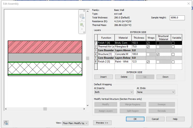
STEP 12 : Walls with appropriate materials and finishing is created in the model.
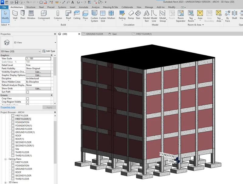
STEP 13 : Exterior facade with finishing is created.
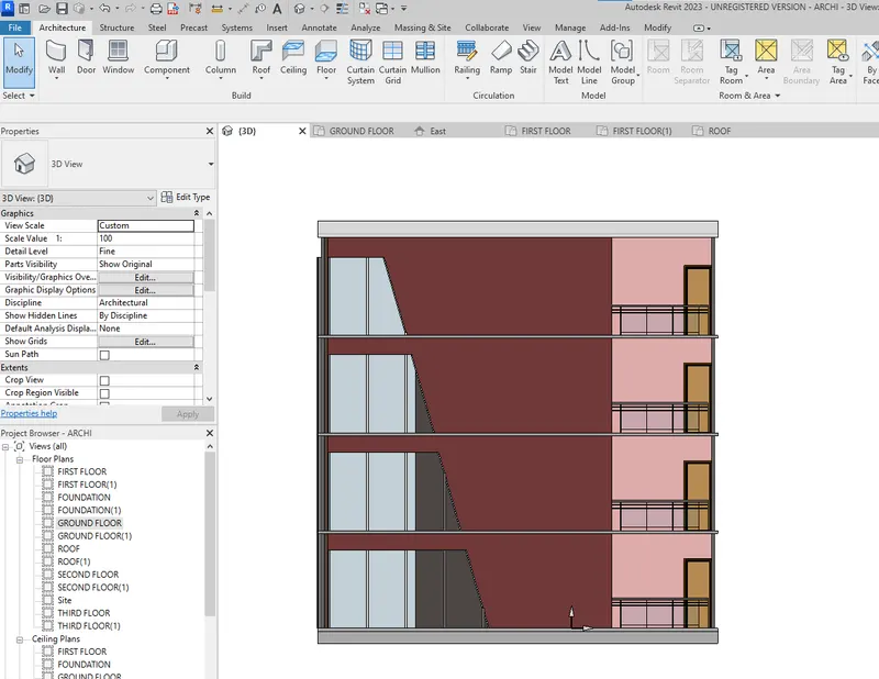
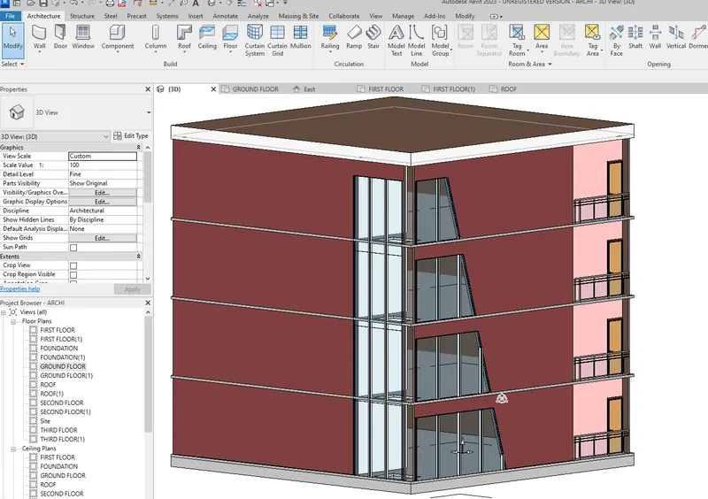
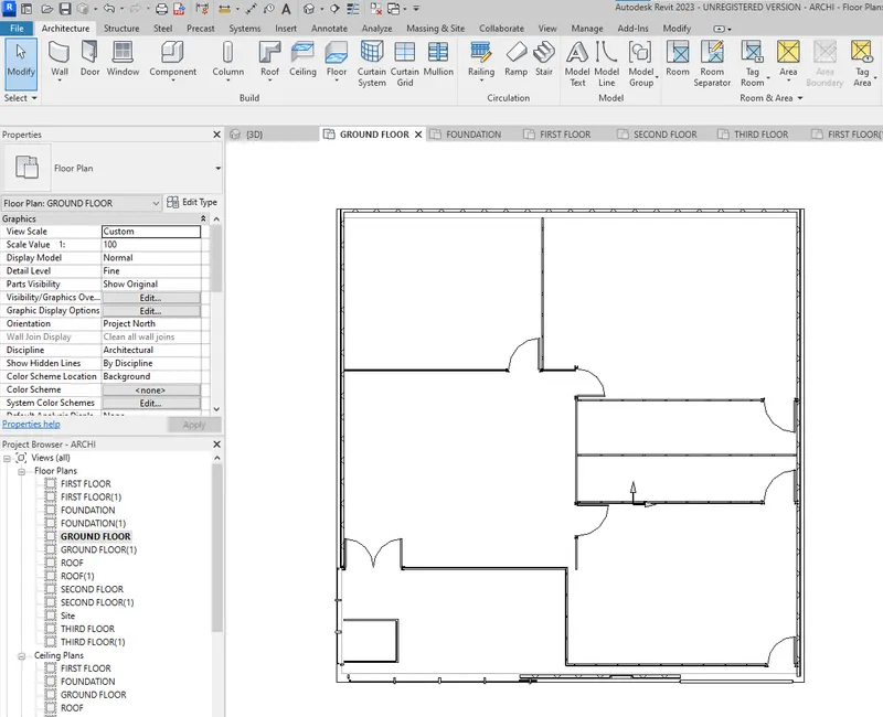
STEP 14 : To create interior partition walls, click on Architecture -> Walls ->Wall : Architectural. And draw the walls in the appropriate location using line tool.
STEP 15 : To create staircase, Click Architecture -> Stair and place in the desired location.
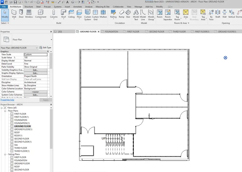
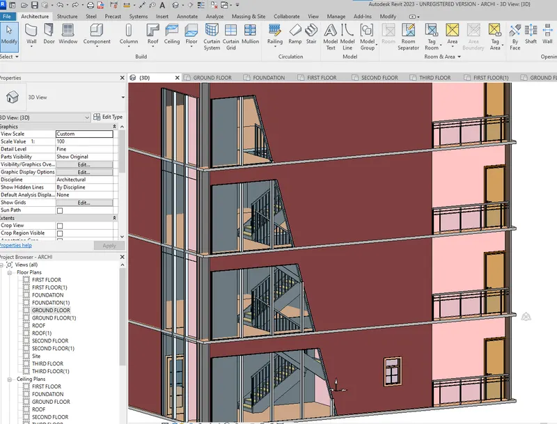
STEP 16 : To include various components in the building, click on Component -> Place a component.
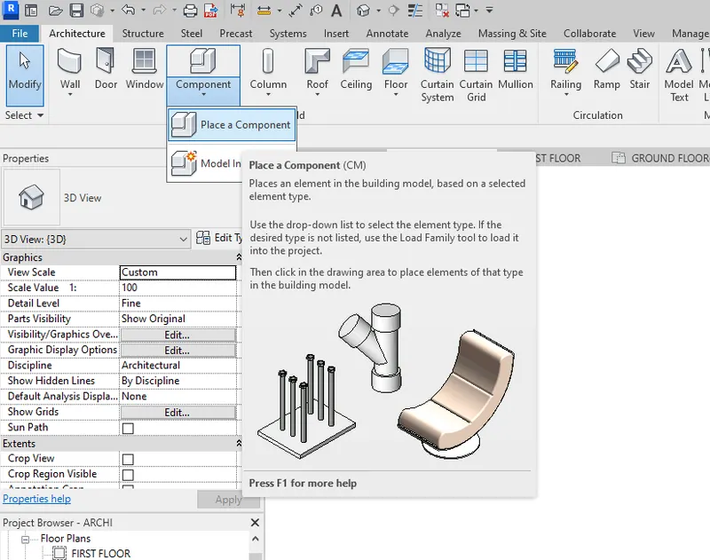
STEP 17 : Now click on the Load Family icon to place all the necessary components in the building.

STEP 18 : All the necessary components of the building are placed appropriately.
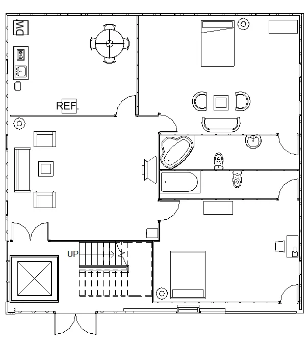
STEP 19 : Glass panels are added in front side of the building.
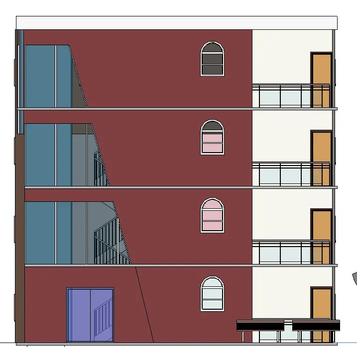
STEP 20 : To add topography, Click -> Massing & Site -> Toposurface

STEP 21 : Now Click, Place point to add the boundary points to create the surface

STEP 22 : The surface is now created.
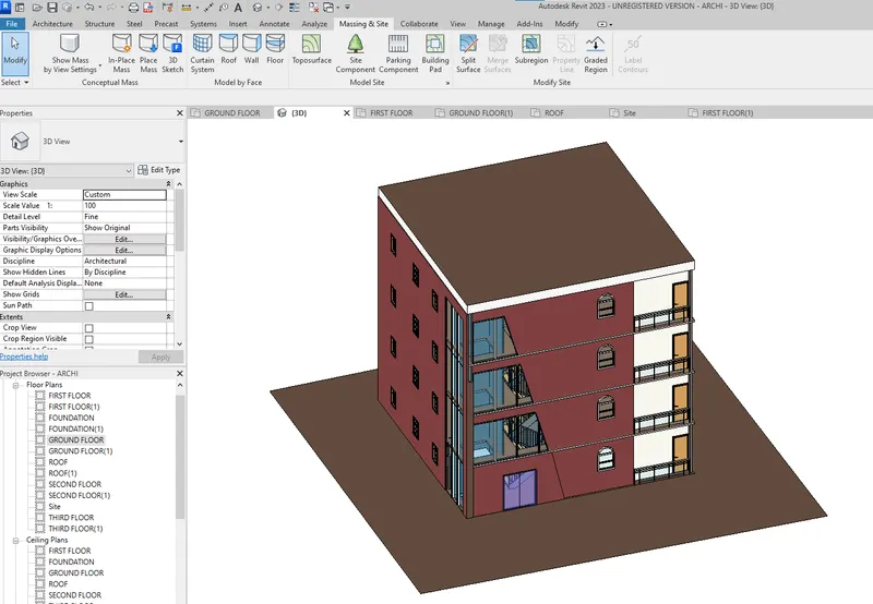
STEP 23 : Place the lighting fixtures, plants, parking in the building using the tab Component -> Place a component -> Load Family.
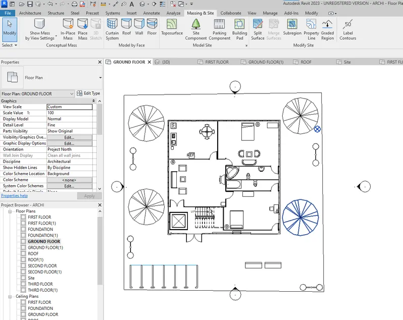
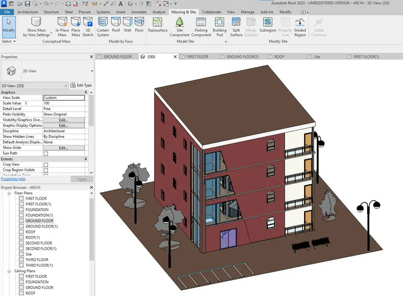
RESULT :
Thus using the architectural model, all the appropriate components based on the type of structure selected were added.
5) Provide a set of drawings in an architectural and structural model to list the following details with categories and appropriate sheet templates included
a. Floor Plans with Annotations
b. Elevations
c. Sections
AIM :
To provide a set of drawings in an architectural and structural model to list the following details with categories and appropriate sheet templates included
a. Floor Plans with Annotations
b. Elevations
c. Sections
PROCEDURE :
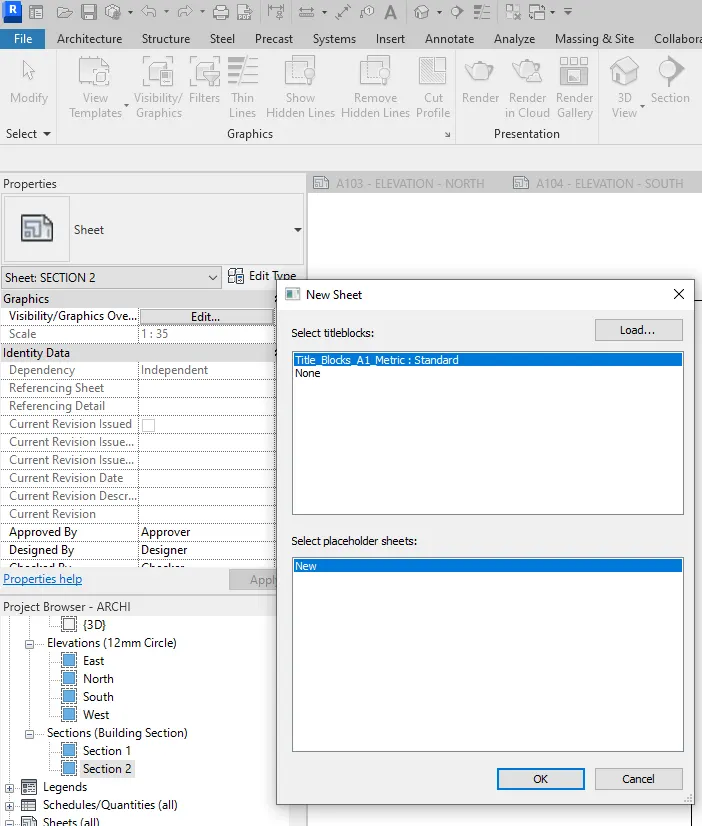
STEP 1 : To create the sheet, Click View -> Sheet icon.

STEP 2 : A dialog box opens, select the desired titleblocks and click OK.
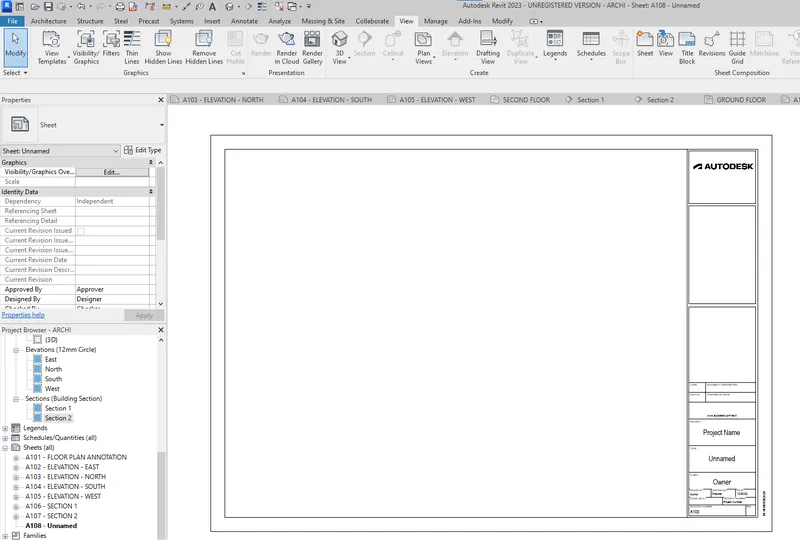
STEP 3 : A new sheet will be created.
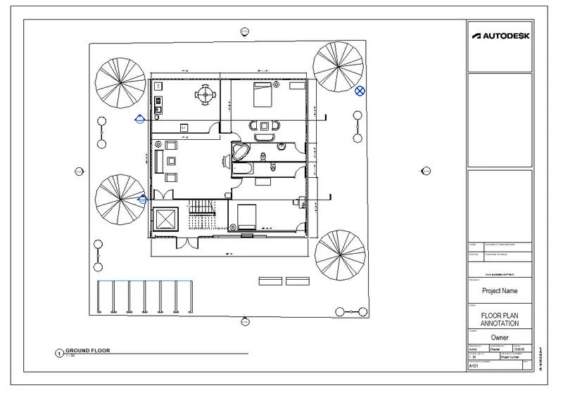
STEP 4 : To copy the any of the required views in the sheet, go to Project Browser and select the required view, drag and drop into the sheet.
A101 - FLOOR PLAN WITH ANNOTATION :
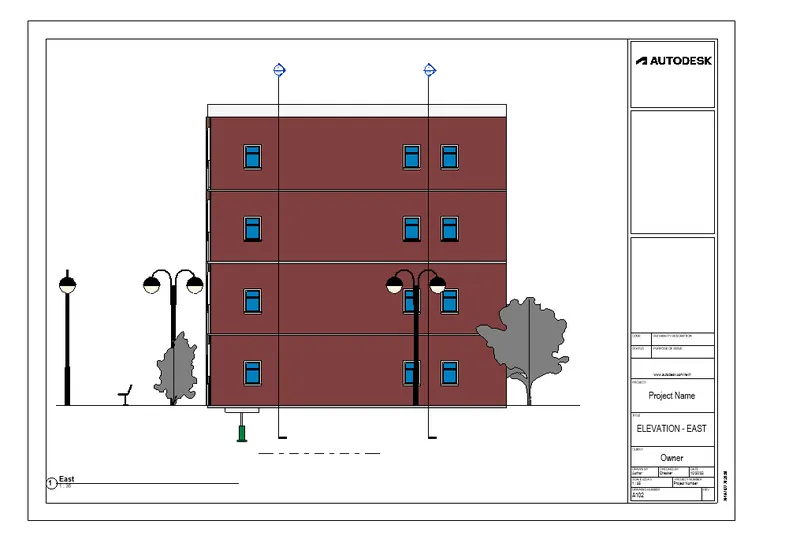
A102 - ELEVATION EAST
A103 - ELEVATION NORTH
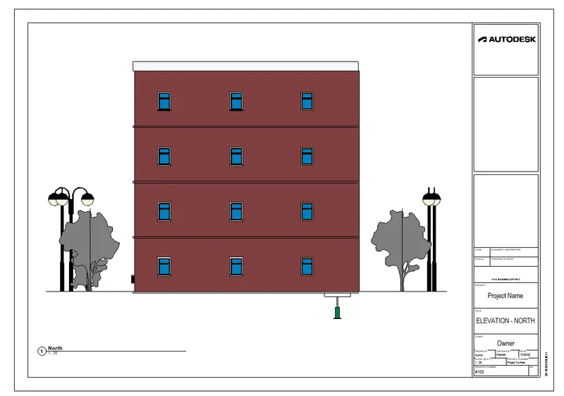
A104 - ELEVATION SOUTH
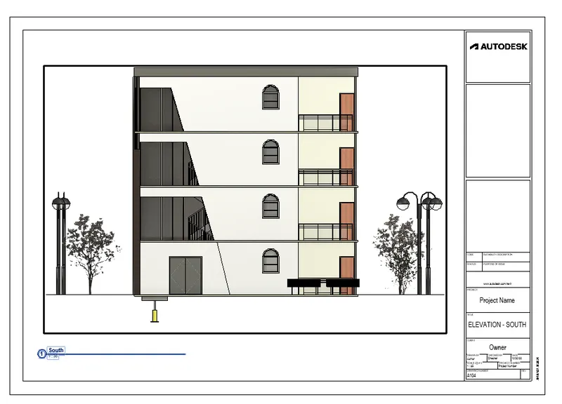
A105 - ELEVATION WAST
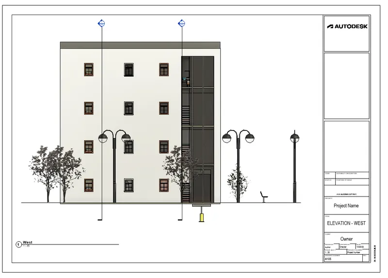
A106 - SECTION 1
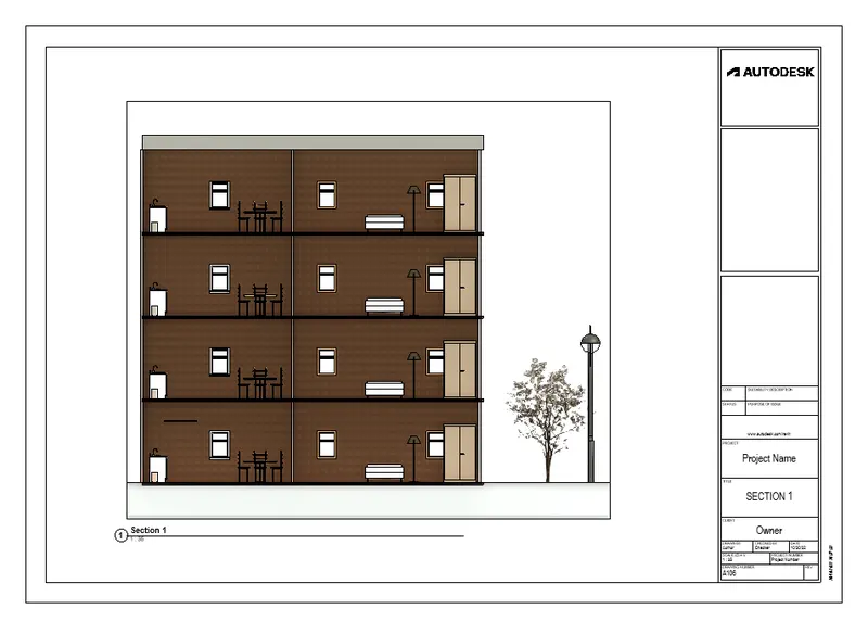
A107 - SECTION 2
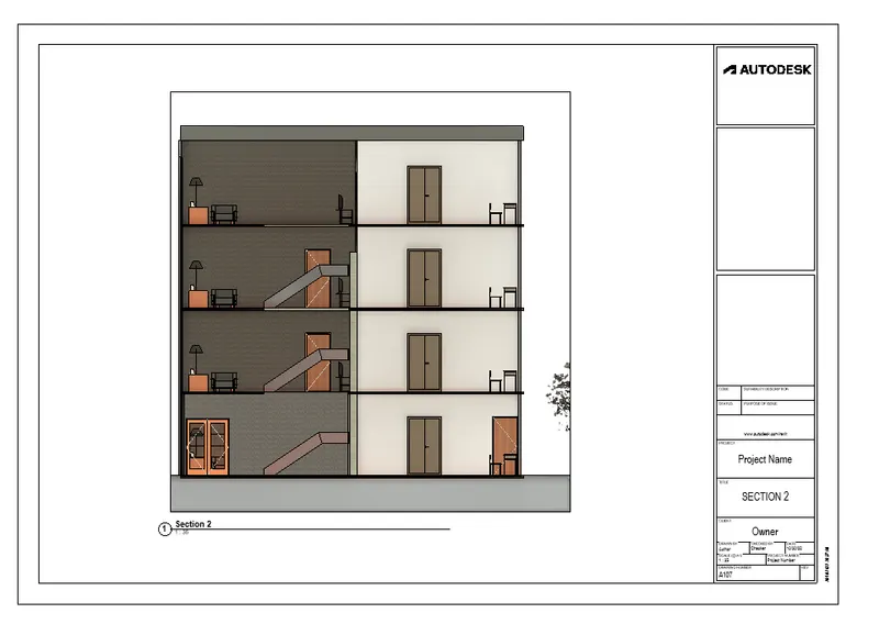
RESULT : Thus various sheets containing floor plan annotation, Elevations and Sections are created.
6) Using the Rendering settings, Render images of the 3D model produced and include the rendered images to the drawing sheets
a. Rendering from interior rooms
b. Rendering from out showing topographic features
c. Rendering through structural framing
AIM :
To render images of the 3D model produced and include the rendered images to the drawing sheets using Render settings
a. Rendering from interior rooms
b. Rendering from out showing topographic features
c. Rendering through structural framing
PROCEDURE :
STEP 1 : To render the model, make camera view of the specified area by clicking on the camera icon from the tool bar.
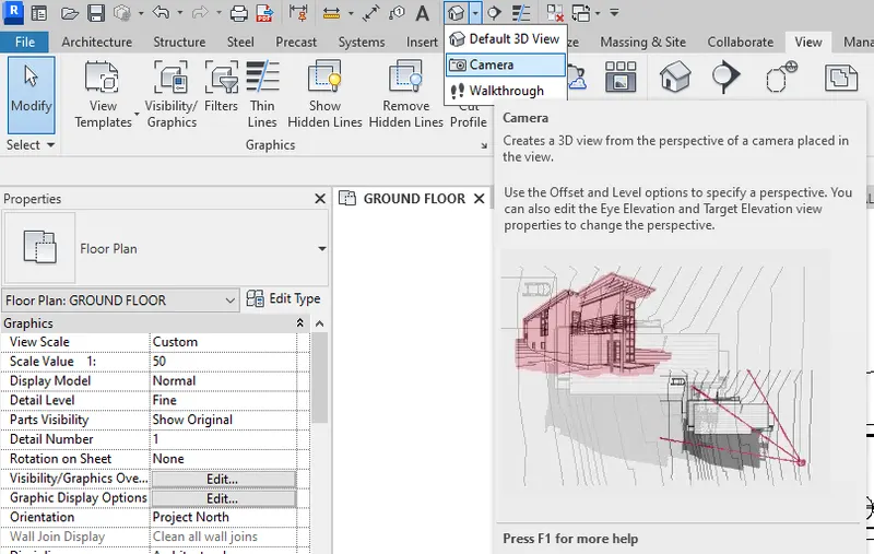
STEP 2 : Camera icon appears, now place the icon in the appropriate location to create the 3D camera view of the place.
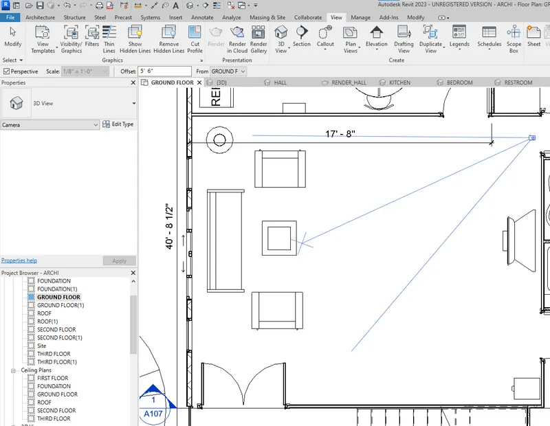
STEP 3 : Go to the 3D camera view created.
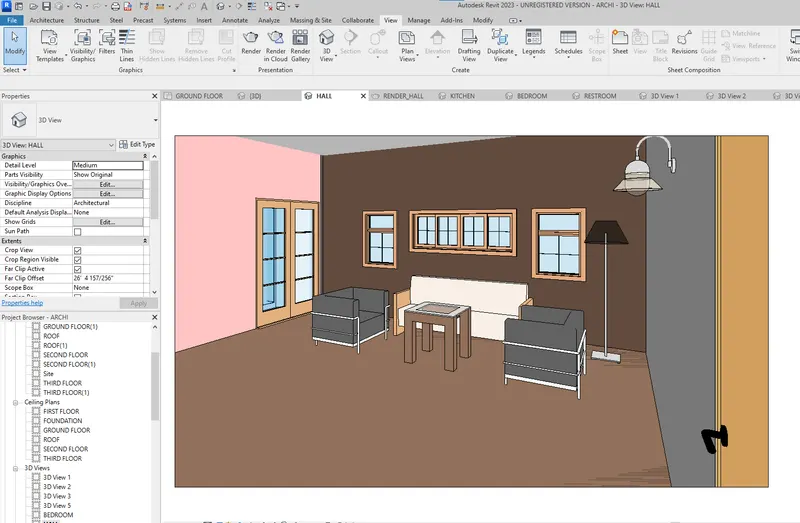
STEP 4 : Click on View -> Render to render the view created.

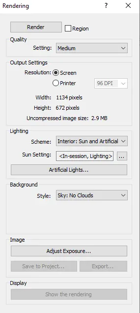
STEP 5: A dialog box appears, select the desired parameters accordingly and click on Render.
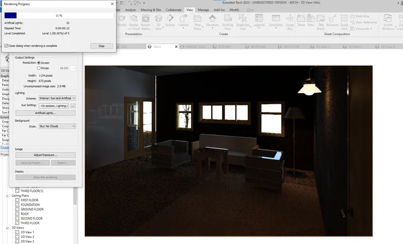
STEP 6: After clicking on Render, the rendering process starts.
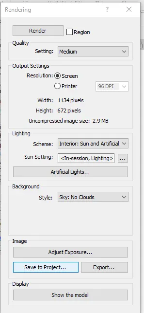
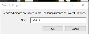
STEP 7: Click on the Save to Project, to save the created rendered view and enter the file name and click OK.
STEP 8: Rendered view of the Hall is as below.
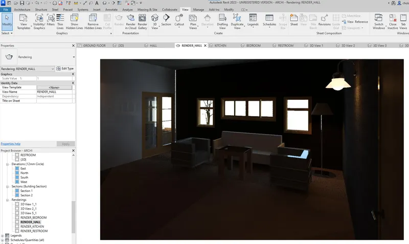
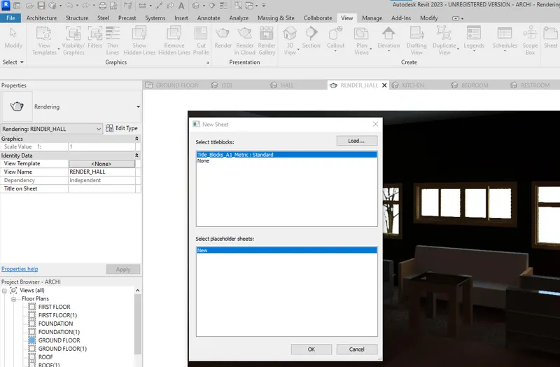
STEP 8: To insert this rendered view in sheet, click on View -> Sheet. A dialog box appears, load the sheet size and click Ok.
STEP 9: Sheet is created. Change the file name and Now drag and drop the rendered view created from Project Browser -> Renderings.
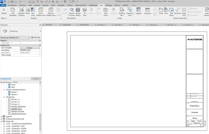
STEP 10: Sheet is created. Change the file name and Now drag and drop the rendered view created from Project Browser -> Renderings.
A108 - RENDER_HALL
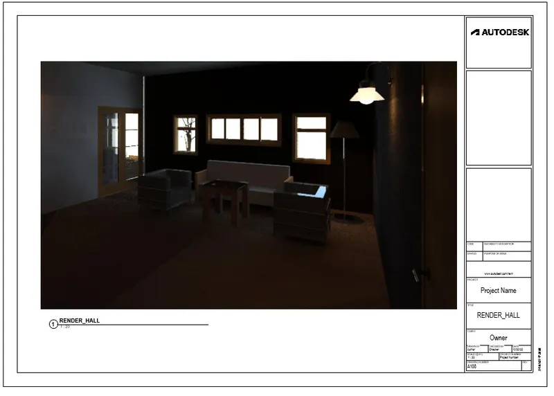
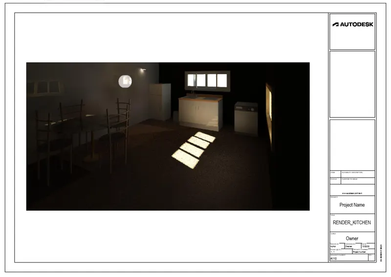
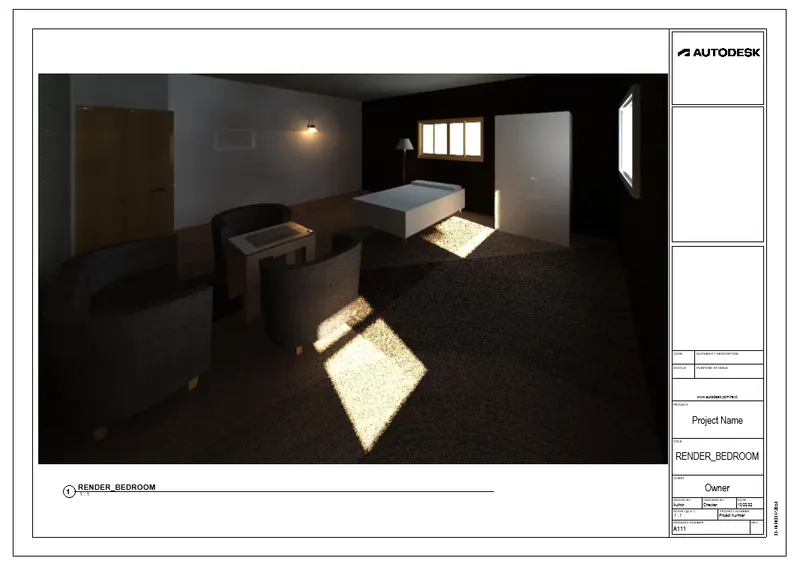
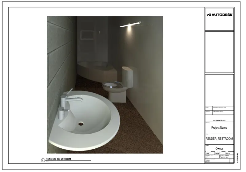
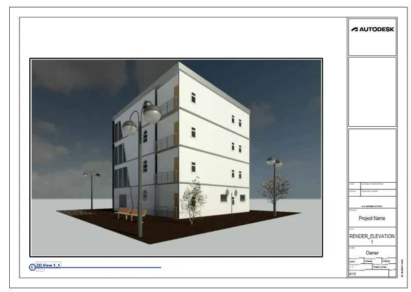
STEP 11: Similarly create render view of the all the other locations, and place it in sheet as below.
A110 - RENDER_KITCHEN
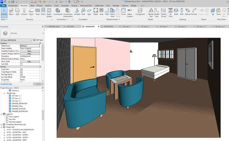
A111 - RENDER_BEDROOM
A112 - RENDER_RESTROOM
A113 - RENDER_ELEVATION 1
A114 - RENDER_ELEVATION 2
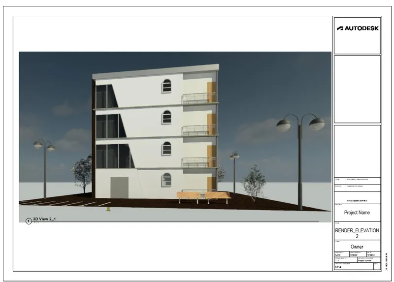
A115 - RENDER_ELEVATION 3
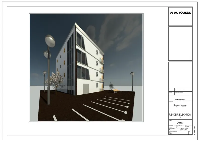
RESULT : Thus render images of the 3D model is produced and included the rendered images to the drawing sheets using Render settings.
7) Print the set of drawing sheets created and submit the drawings from the architecture and structure model.
AIM :
To Print the set of drawing sheets created and submit the drawings from the architecture and structure model.
PROCEDURE :
STEP 1 : Select the view which should be printed. Double click the view. The selected view displays.
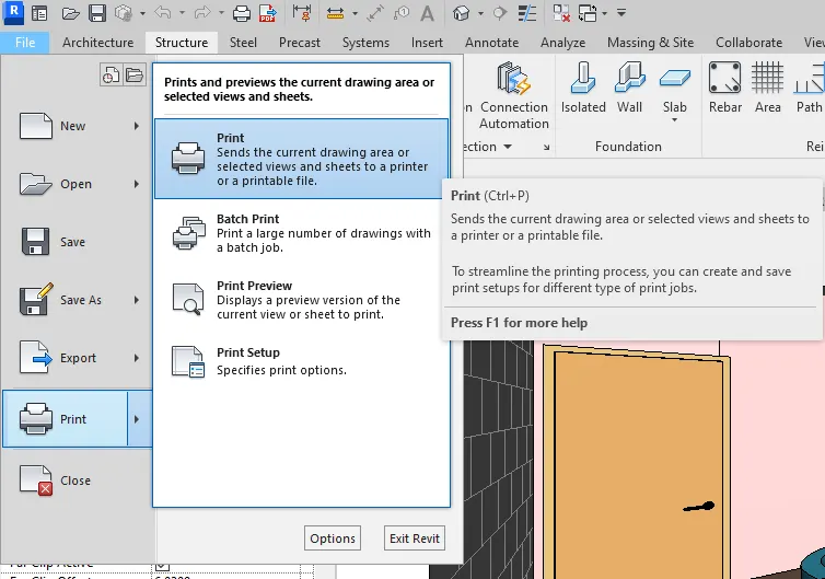
STEP 2 : Click File -> Print -> Print
STEP 3 : Select the printer type from the Name drop down list.
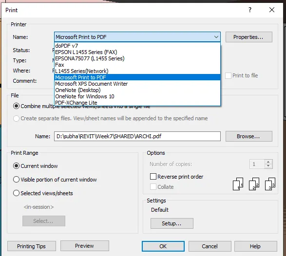
STEP 3 : Click Preview option from the dialog box to preview the layout.
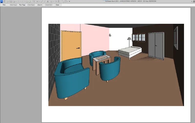
STEP 3 : Click on the option Print at the top left of the preview screen to print the layout. Click OK.
STEP 4 : To save the layout as pdf, Click Print -> From the Name drop down list, select PDF-XChange Lite option and Click OK.
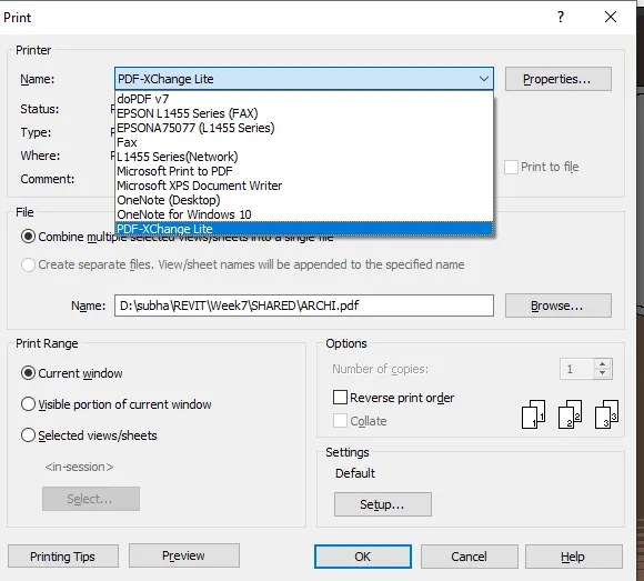
STEP 5 : To save the layout as pdf, Click Print -> From the Name drop down list, select PDF-XChange Lite option and Click OK. The selected layout will be saved as pdf in the desired location.
RESULT :
Thus the created sheets are printed accordingly.