Creating Architectural and Structural model with 3D rendering using REVIT
1) Select the type of structure you want to build from one of the three below:
a. Multi-Unit Residential Apartment
b. Office Buildings
c. School
Ans:
school structure is selected to model
2) Assume reasonable assumptions for geographic and location details for your project modeling. Based on assumptions and type of structure selected identify the modeling requirements from NBC
Ans:
assumptions for geographic and location details for your project modeling. Based on assumptions and type of structure selected identify the modeling requirements from NBC:
• Height of level is assumed as the 3.5m
• Class rooms of size 8m*8m was assumed
• One lift and staircase to be provided
• Total plot of 44*51m is assumed
• Provide class room, library, male and female toilets and play ground
• Bike park provision and security room
• Assume external lightings
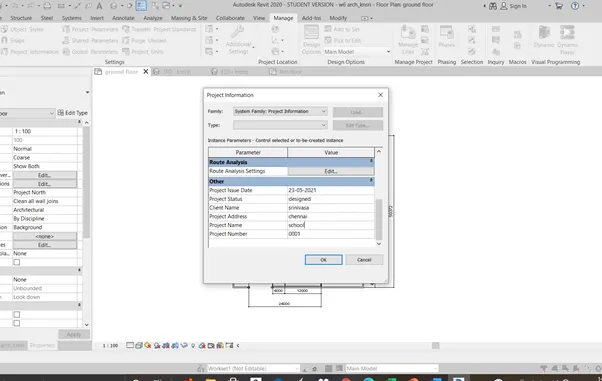
enter the project information
3) Using the structural model, include the following components based on the type of structure selected
Aim:
Creation of the structural model
a. Foundation – Isolated / Wall/Matt Foundation
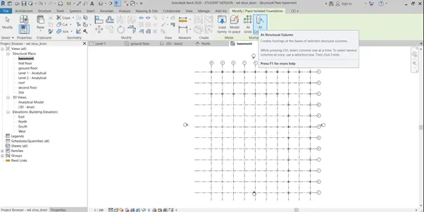
• After completion of the columns
• Go to the menu bar and
• Select the structure command bar
• And select the isolated option
• And click on the at columns option and select all the columns
• Therefore footing will be created as shown in below figure
b. Columns
I. Grids Transverse Grids A, B, C, D, E @ 4m spacing
II. Longitudinal Grids from 1 to 10 @ 4m spacing
III. These grids are placed using the offset command
IV. Go to menu bar
V. Select column in structure command bar
VI. Add the desired dimensions in the property bar
VII. And using the at grids option place the columns at the desired region.
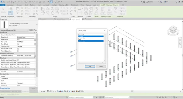
VIII. And the set its constraints of the base and top level
IX. And select all the columns and copy and paste at the aligned levels for the different levels as shown below.
c. Beams Connected to Columns
I. Go to menu bar
II. Select beam in structure command bar
III. Add the desired dimensions in the property bar
IV. Select option at grids and
V. place the beams at the required grids as shown below
VI.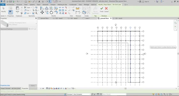
VII.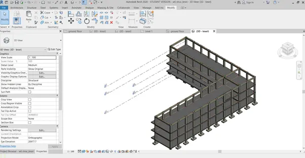
VIII. Go to menu bar
IX. Select beam system in structure command bar
X. Add the desired spacing dimensions in the property bar
XI. Snap the beam system in the required direction
XII.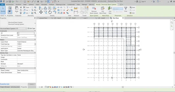
XIII.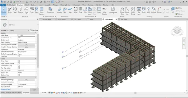
XIV. Beam system is created
d. Roof Framing/ Truss
I. Go to menu bar
II. Select truss in structure command bar
III. Add the desired spacing dimensions in the property bar
IV. And snap on the desired location
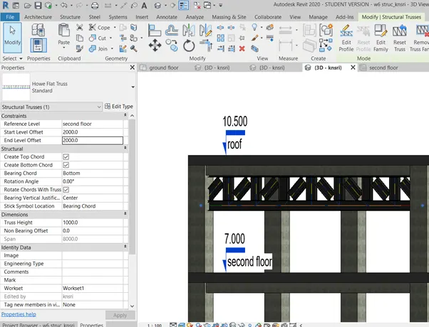
V. And then specify the start offset and end offset as desired
VI. Then we obtain the truss as the figure below.
e. Floor / Decks
I. Go to menu bar
II. Select floor in structure command bar
III. Add the desired dimensions in the property bar
IV. Sketch the required floor layout in the plan with closed boundary in the line command
V.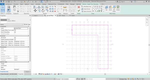
VI. Ok
VII. And copy the floor created to the desired level.
f. Floor Openings for Elevators and Stairs
I. Go to menu bar
II. Select shaft in structure command bar
III. Add the desired dimensions in the property bar
IV. Sketch the required floor layout in the plan with closed boundary in the line command by having the reference of the lift and staircase
V. Provide its base and top constraint
VI. And copy the shaft to desired levels
VII. And thereby opening is created
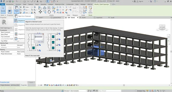
Result:
Structural model was created. this is the skeleton of the building which shows the position of the columns , beams and type of the floors all can be modified and placed.
4) Using the architectural model, include the following components based on the type of structure selected
Aim:
In the architectural model, include the following components based on the type of structure selected
a. Wall Layout with appropriate material and finishing
I. Go to menu bar
II. Select wall in architecture command bar
III. And snap on the plan view for the exterior walls plans
IV. Select the walls and in the properties command bar click on edit type.
V. And load the required properties to the wall
VI. Here material can also be loaded
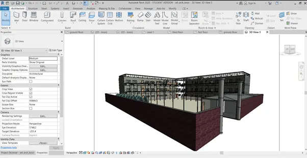
b. Exterior façade with fancy finish
c. Interior partition walls to size rooms
I. Go to menu bar
II. Select wall in architecture command bar
III. And snap on the plan view for the exterior walls plans
IV. Select the walls and in the properties command bar click on edit type.
V. And load the required properties to the wall
VI. Here material can also be loaded
VII. And snap all the required locations to place the wall
VIII. Select all the interior wall and copy to clipboard and paste to the aligned levels
IX.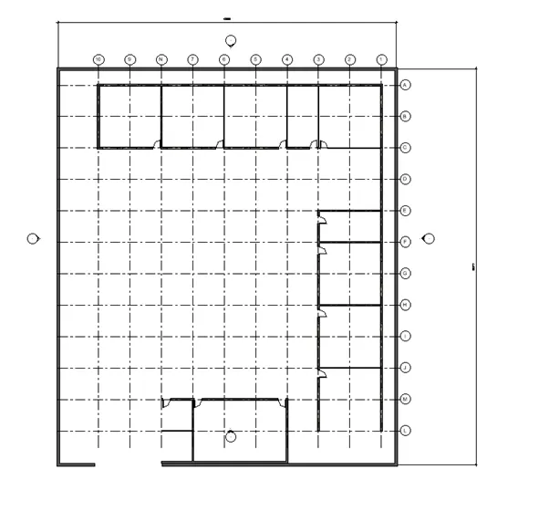
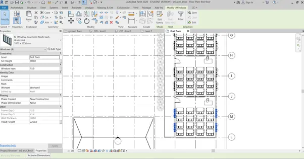
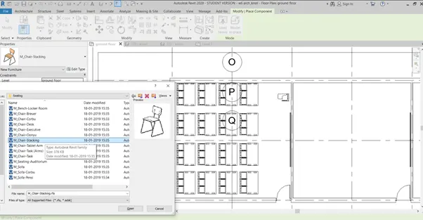
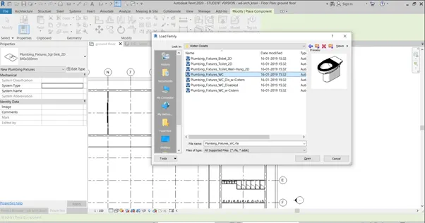
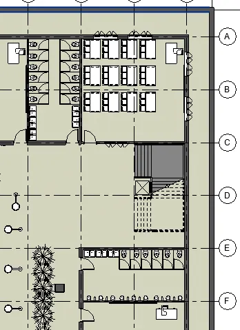
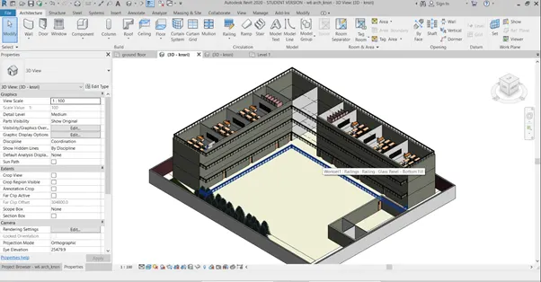
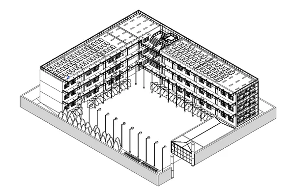
d. Components to add details to a room ( Desk, Chair, Lighting, Plumbing fixtures)
I. Go to menu bar
II. Select the architecture tab
III. Now select the component option
IV. In the properties tab drop down select sofa the required size
V. And by snapping place the component at the required position
VI. In the properties tab drop down select coffee desk the required size
VII. And by snapping place the component at the required position
VIII. In the properties tab drop down select tv the required size
IX. And by snapping place the component at the required position
X. In the properties tab drop down select chair the required size
XI. And by snapping place the component at the required position
XII. Click on the chair
XIII. And the in-menu bar selects the rotate
XIV. Then specify the direction and type 90
XV. Therefore chair is rotated to the required angle
XVI. If any of the component is not present
XVII. Then go to insert
XVIII. And click on load family
XIX. In the particular family category load the required instance and follow the normal procedure
XX.
e. Add components such as stairs Elevators
I. Go to menu bar
II. Select the architecture tab
III. Now select the component option
IV. In the properties tab drop down select elevators the required size
V. And by snapping place the component at the required position
VI. Go to menu bar
VII. In the architecture command bar
VIII. Select the stair option
IX. Draw the stairs using the run and landing command an enter
X.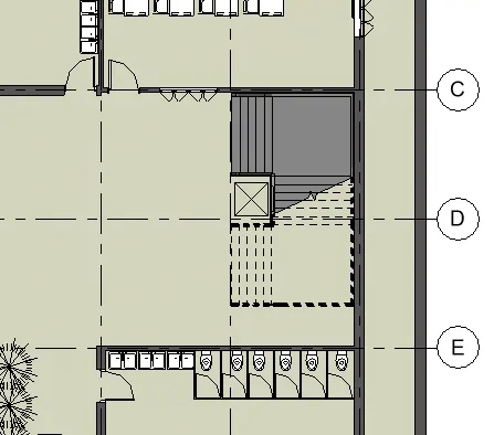
XI. And using elevation view connect the levels of the stair
XII.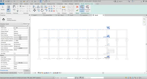
XIII.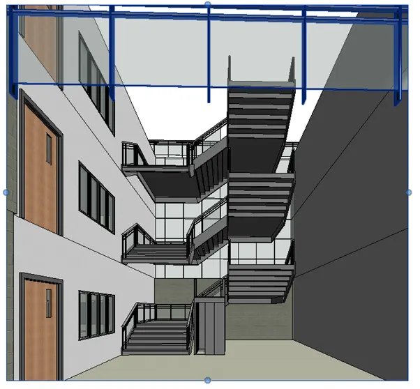
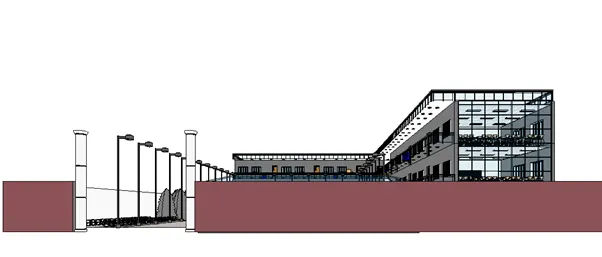
f. Have at-least one side of the building with curtain walls and glass panels
I. After the creation of the wall
II. Trim the area where the wall has to curtened and draw the new wall there
III. Select all the wall curtain has to be done
IV. And properties tab select the curtain wall
V. And by using edit type edit the spacing of the grids of the wall
VI.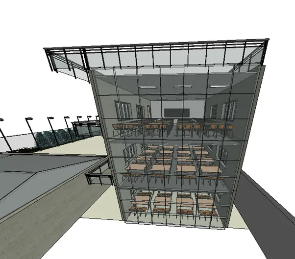
VII.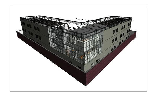
g. Include interior and exterior lighting fixtures
I. Go to menu bar
II. Select the architecture tab
III. Now select the component option
IV. In the properties tab drop down select lighting system the required size
V. And by snapping place the component at the required position in the ceiling plan
VI. Same for the external lighting
VII.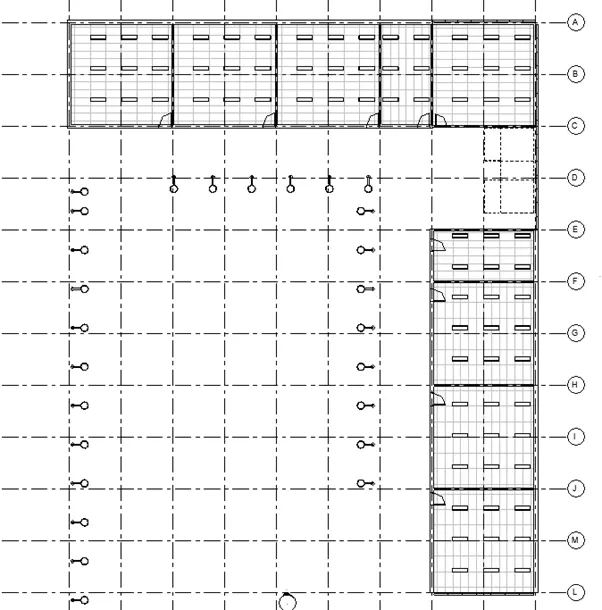
VIII.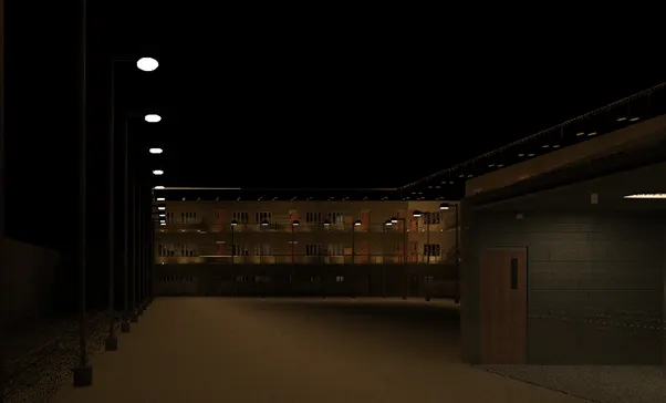
IX.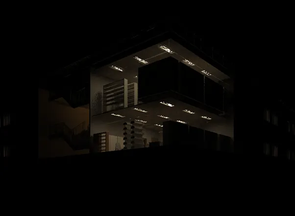
h. Place proper topographic components from outside ( Trees, Parking, Plants) to add details to the model
I. Go to menu bar
II. Select the architecture tab
III. Now select the component option
IV. Load family and select the desired planting
V. In the properties tab drop down select planting the required size
VI. And by snapping place the component at the required position
VII. And same for the parking
VIII. And for topography
IX. Go to massing and siting
X. Select the topography and pick the points in the ground floor
XI. And the material to the topography created as it is sand in this project. As shown in the figure below
XII.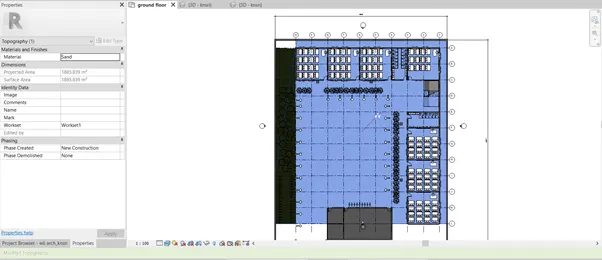
XIII.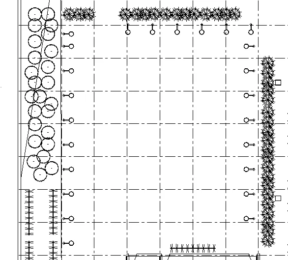
XIV.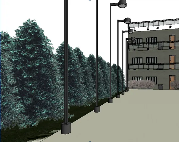
XV.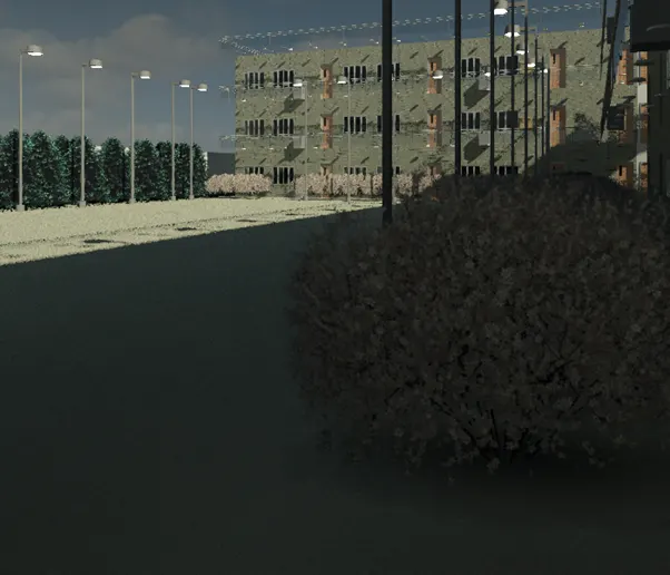
Result:
the architectural model, included with the required components based on the type of structure selected was made.
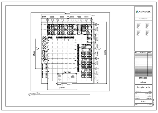
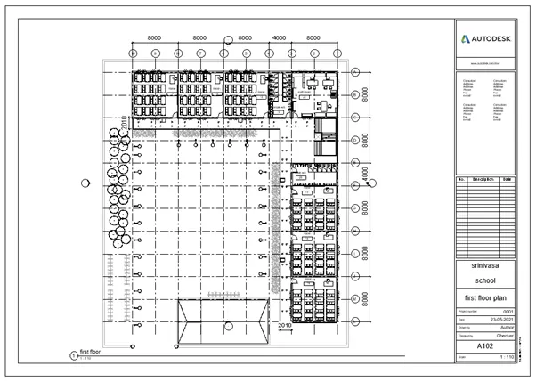
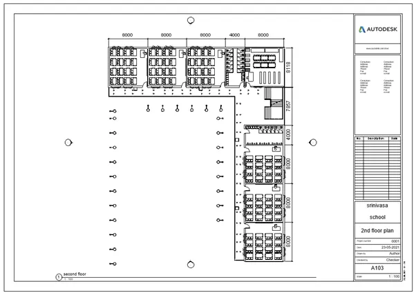
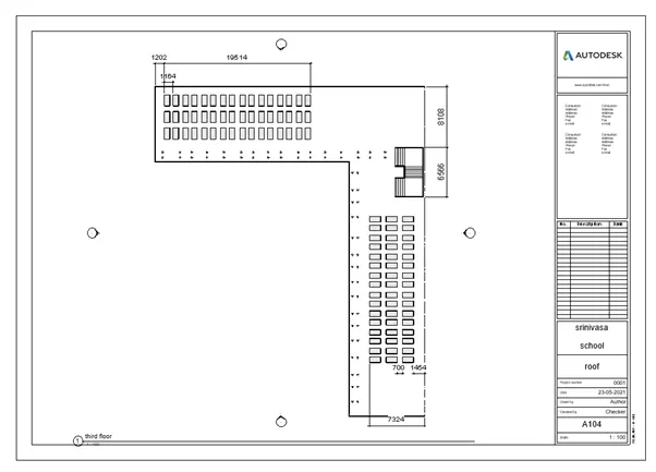
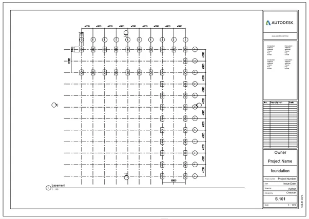
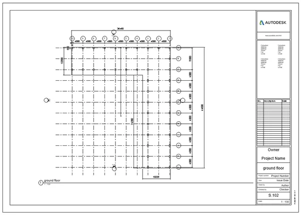
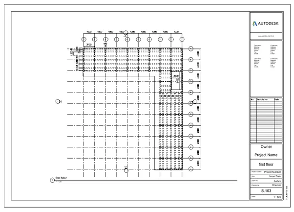
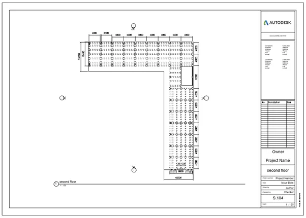
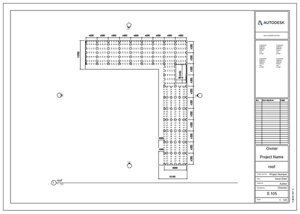
5) Provide a set of drawings in an architectural and structural model to list the following details with categories and appropriate sheet templates included
Aim:
Create the sheet templates with the following views
I. Adding the views to the sheet
II. Go to the view command in the title block
III. Click on the view option
IV. And in the pop up select the required view to be displayed in the sheet
V. And click ok
VI. Sheet shown in the following images will be obtained
a. Floor Plans with Annotations
architectural:
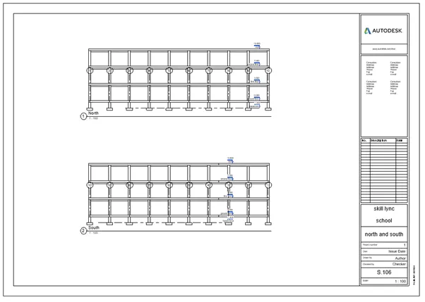
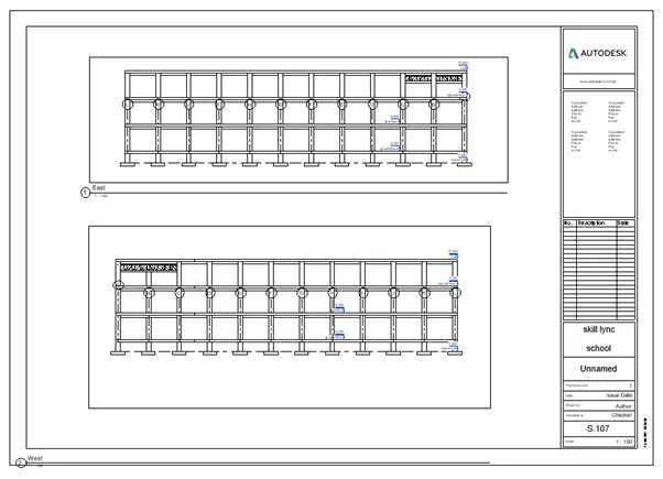
Structural drawings:
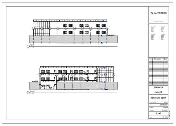
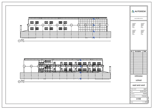
b. Elevations
c. Sections
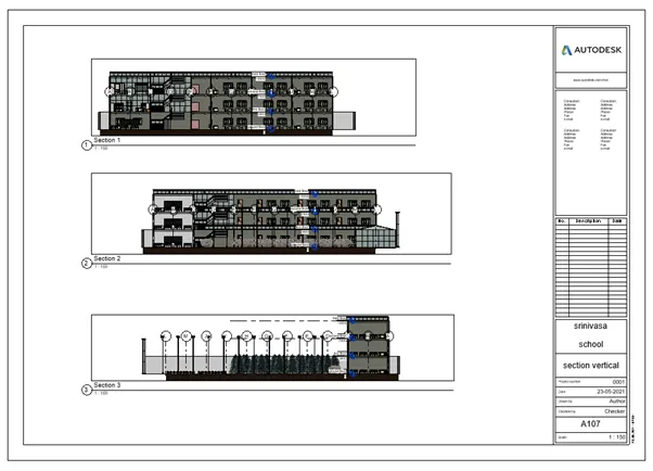
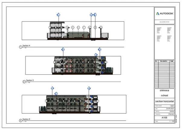
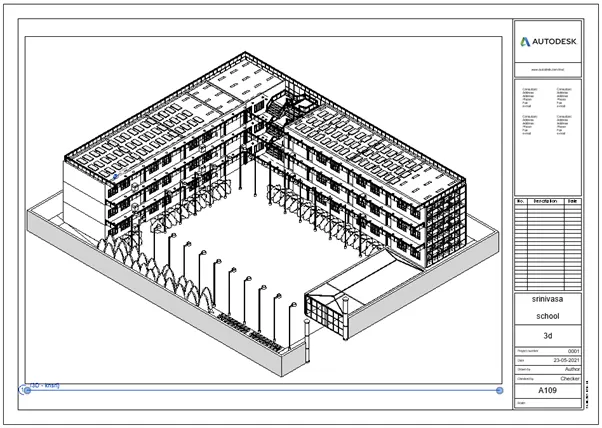
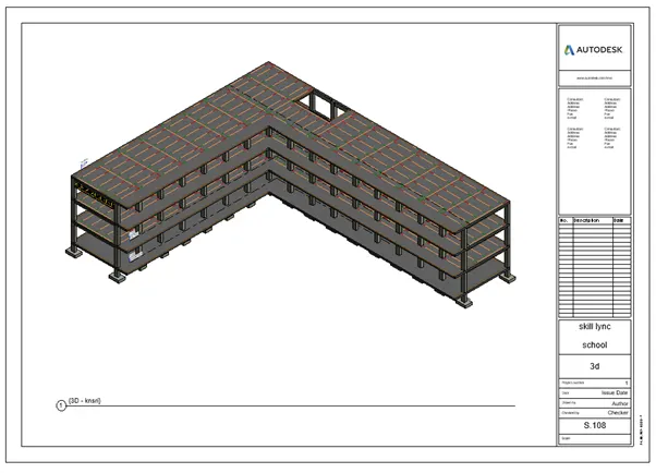
Result:
All set of drawings in an architectural and structural model to list the following details with categories and appropriate sheet templates included was provided
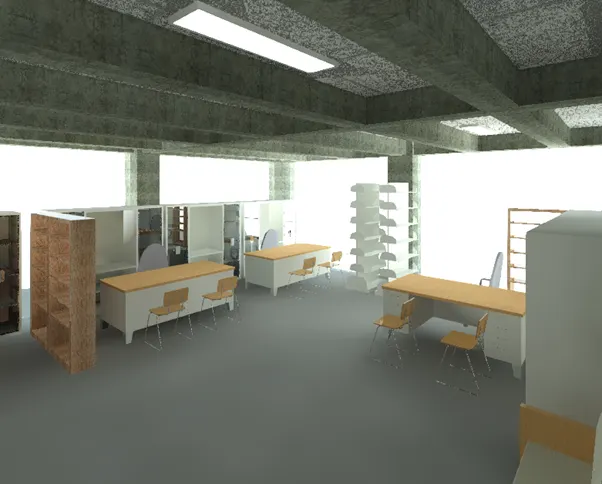
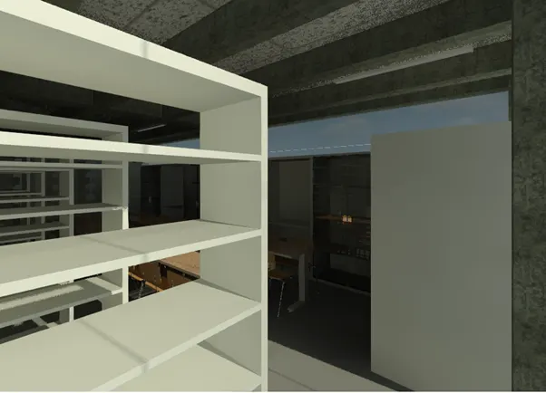
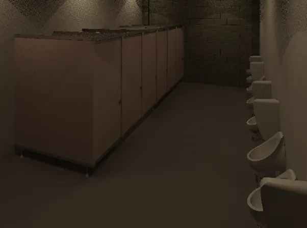
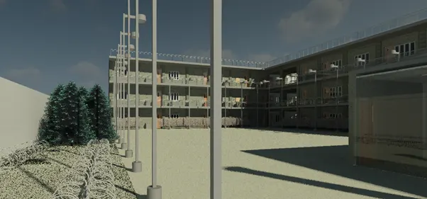
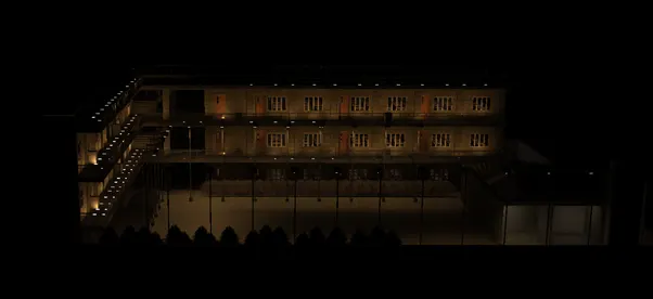
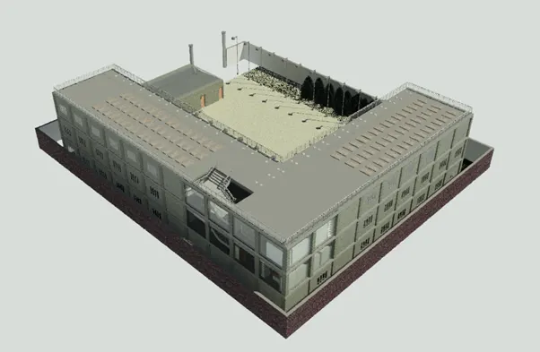
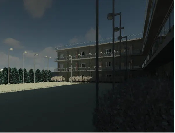
6) Using the Rendering settings, render images of the 3D model produced and include the rendered images to the drawing sheets
Aim:
Creation of the rendered images
Procedure:
I. Go to view bar and select camera
II. Snap the camera position in the floor plan
III. And drag its projection
IV. ok
V. In keyboard type RR
VI. There will be a popup of the render command
VII.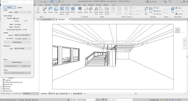
VIII. Then change the required scheme in the tab
IX. And click on ok.
X. Then we obtain the render image.
a. Rendering from interior rooms
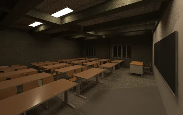
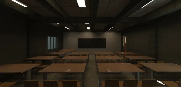
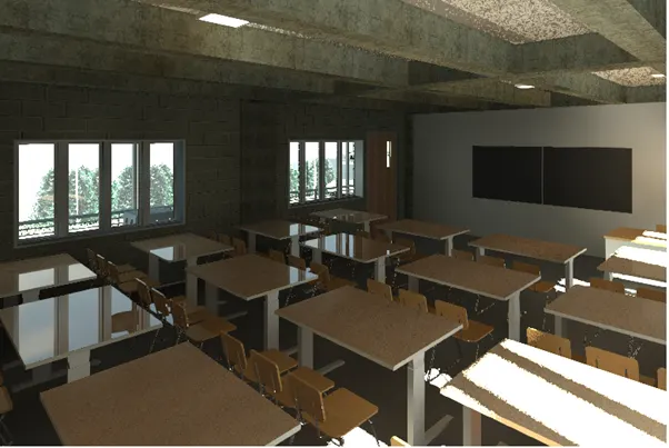
b. Rendering from out showing topographic features
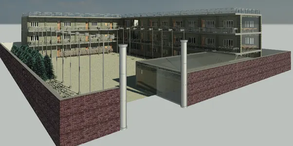
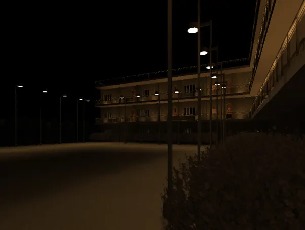
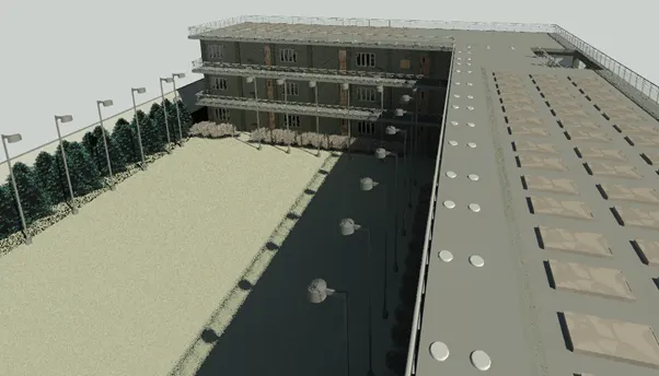
c. Rendering through structural framing
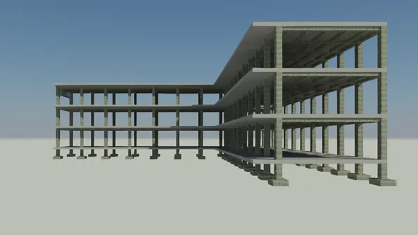
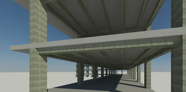
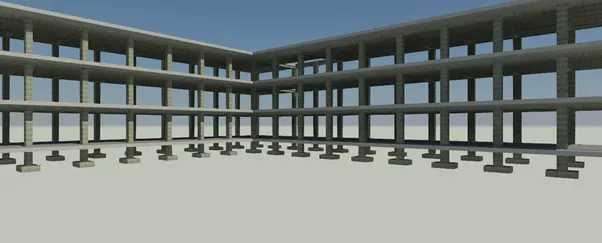
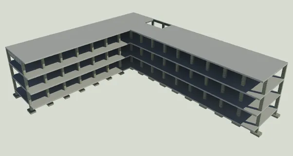
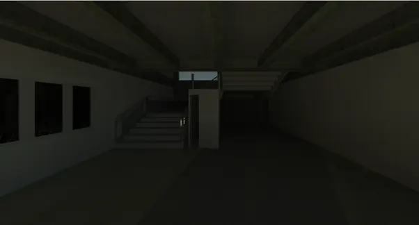
Result:
All required render images were obtained
7) Print the set of drawing sheets created and submit the drawings from the architecture and structure model
Aim:
To print the certain set of drawings
Procedure:
I. Go to file
II. Select print
III. Then in the popup select the print range as the selecteted views or sheets
IV. And then select the required sheet
V. And ok.
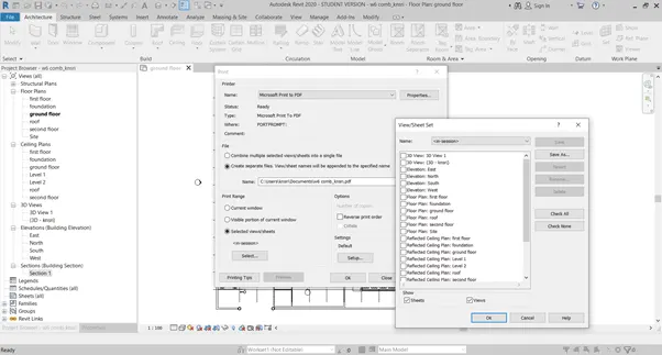
Result:
Required sheet was able to print.