Creating an Architectural plan for the provided plot size and develop relevant basic structural drawings
1.
Aim:
Design and Draft of a layout of a residential building with the following details:
a. Plot Size: 60’x20’(18.3m x6m)
b. Orientation- Facing East
c.Develop the following: 1. Architectural Drawing (Floor Plan, Elevations, and Sections) 2. Structural Drawing (Column, Bean, Footing Plan)
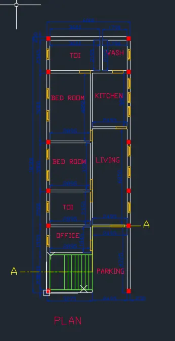
- In command prompt type (startup:1)
- Then file>new
- Then create new drawing window select metric in default settings
- In advanced setup in units check on the decimal, angle in degrees, then ok
- In command prompt type (xl enter h enter v) construction line horizontal and vertical respectively is obtained
- Next, in command prompt type (o and specify distance of offset as 3000) and offset the horizontal line to top
- Next, in command prompt type (o and specify distance of offset as 1800) and offset the horizontal line to top
- Next, in command prompt type (o and specify distance of offset as 2500) and offset the horizontal line to top
- Next, in command prompt type (o and specify distance of offset as 3500) and offset the horizontal line to top
- Next, in command prompt type (o and specify distance of offset as 5000) and offset the horizontal line to top
- Next, in command prompt type (o and specify distance of offset as 3000) and offset the horizontal line to top
- Next, in command prompt type (o and specify distance of offset as 2500) and offset the horizontal line to top
- Next, in command prompt type (o and specify distance of offset as 4800) and offset the horizontal line to top of bottom line
- Next, in command prompt type (o and specify distance of offset as 7000) and offset the horizontal line to top
- Next, in command prompt type (o and specify distance of offset as 4000) and offset the horizontal line to top
- Next, in command prompt type (o and specify distance of offset as 2200) and offset the vertical line to right
- Next, in command prompt type (o and specify distance of offset as 1000) and offset the vertical line to right
- Next, in command prompt type (o and specify distance of offset as 2800) and offset the vertical line to right
- Next, in command prompt type (o and specify distance of offset as 2400) and offset the vertical line to right
- Next, in command prompt type (o and specify distance of offset as 2300) and offset the vertical line to right
- Offset all exterior lines to 230 inwards and offset all interior line for 75 on both sides and delete the original line
- Now, trim and fillet all the required lines
- Create a block of the square of 250*250 as column and co this blocks to the required positions
- Now using rectangle command draw the rectangle boundary for the staircase and explode the rectangle and oddest it by 250mm.
- Create a block of the rectangle as window and doors and co this blocks to the required positions
- Select all create a layer of walls in orange colour
- Select dim laver and type dim in prompt command or select linear dimension in the annotation bar and measure the dimension
- Then type dimcon and do the dimension continuously
- Select all dimension and type DIMSPACE and provide the equal spacing for all the dimensions
- By typing dtext provide the heading for all the drawings and select the layer as the anno
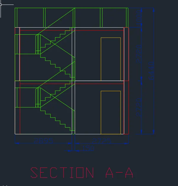
- Section AA
- SELECT THE GREEN LAYER FOR STAIRCASE
- draw one raiser and footer and ten copy to the top floor
- and draw the parallel line to the steps with snapping
- form the parallel lines draw the railings of the stairs
- In command prompt type (xl enter h enter v) construction line horizontal and vertical respectively is obtained
- Next, in command prompt type (o and specify distance of offset as 2720) and offset the horizontal line to top
- Next, in command prompt type (o and specify distance of offset as 2895) and offset the vertical line to right
- Next, in command prompt type (o and specify distance of offset as 150) and offset the vertical line to right
- Next, in command prompt type (o and specify distance of offset as 2725) and offset the vertical line to right
- Draw a rectangle with the column layer of 250*2750 at both the corner and offset 150 of the top line and set to current layer as beam
- And copy the entire objects as the 2nd floor
- Draw a 1000mm vertical line at top floor and offset to the required positions and draw the horizontal line connecting last lines.
- Select dim laver and type dim in prompt command or select linear dimension in the annotation bar and measure the dimension
- Then type dimcon and do the dimension continuously
- Select all dimension and type DIMSPACE and provide the equal spacing for all the dimensions
- By typing dtext provide the heading for all the drawings and select the layer as the anno
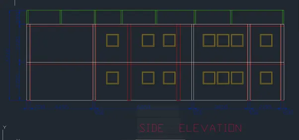
- In command prompt type (xl enter h enter v) construction line horizontal and vertical respectively is obtained
- Next, in command prompt type (o and specify distance of offset as 4800) and offset the vertical line to right of bottom line
- Next, in command prompt type (o and specify distance of offset as 7000) and offset the vertical line to right
- Next, in command prompt type (o and specify distance of offset as 4000) and offset the vertical line to right
- Draw a rectangle with the column layer of 250*2750 at both the corner and offset to all required positions and offset 150 of the top line and set to current layer as beam
- Using rect command draw window and copy to all respective positions
- And copy the entire objects as the 2nd floor
- Draw a 1000mm vertical line at top floor and offset to the required positions and draw the horizontal line connecting last lines.
- Select dim laver and type dim in prompt command or select linear dimension in the annotation bar and measure the dimension
- Then type dimcon and do the dimension continuously
- Select all dimension and type DIMSPACE and provide the equal spacing for all the dimensions
- By typing dtext provide the heading for all the drawings and select the layer as the anno
Result:
For the given condition at first the hand sketch draft file was done for the 60*20 site as depending on that the AutoCAD file was created depleting the draft drawing was drawn as shown in the figure 1 and by this plan consideration a section view and the side elevation was visualised and drawn in the AutoCAD as figure 2 and figure3 respectively and layers columns and beams was used during the drawing which will be helpful in differentiating the architectural and structural drawing which shows the position of the columns and beams
All dimensions and the annotations were provided which are helpful for the drawing standards