Creating a Wardrobe detailed drawing, Floor Plan, Kitchen Layout and Column Detail using AutoCad
Q1
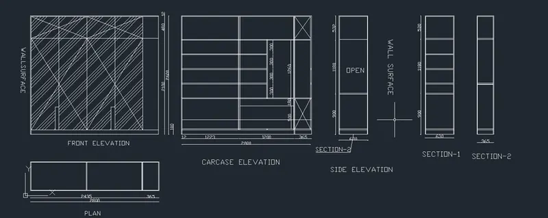
Aim - To draw the cabinet, floor plan, kitchen, column details and raft layout drawings :
PROCEDURE :
- first the open the software
- give the command QNEW and press the ENTERE key
- click on imperical templete
- select ADVANCE SETUP
- unit : decimal , precision :0.00
- angle :decimal degree , precision :0.00
- angle measure : East
- angle direction : closkwise
- area : 20*20
- and finished , lets start
- Command : limmax and set the limets
- command : z ( for zoom )
- enter A for all
- command : rec (for rectangle )
- length :2800
- width 2600
- press : ENTER
- command : o ( for ofset )
- ofset distance :100 ,488, 12, 640
- and give the ofset
- command :L ( for line )
- and draw the the internal lines
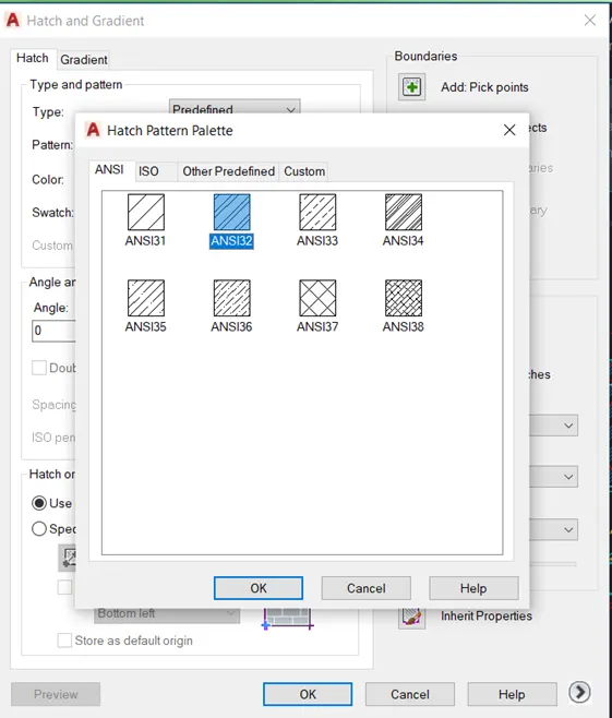
- command : hatch
- select the hatch and give scale of hatch
- press : ENTER
- Command : DIMLIN ( for dimensition )
- give all dimension
- command :DT ( for text )
- write all text
- command : REC ( for rectangle )
- length :2800
- width :2600
- command :o ( for ofset )
- distance :100
- again ofset :
- distance 2435
- then give the 20 mm ofset
- again ofset
- distance : 300 and 20 mm thickness ofset
- then draw the internal parts
- command : DIMLIN ( for the dimension )
- and give the all dimension
- command : DT ( for text )
- write all text
- command : REC ( FOR RECTANGLE )
- length :630
- width :2600
- press :ENTER
- command :o ( for ofset )
- distance :20 mm
- again
- command : o (for ofset )
- distance:900
- command :o
- distance :1180
- command : 0
- distance :520
- command :hatch
- command :DIMLIN (for dimension )
- give the dimension
- command : DT ( for text )
- write all text
- command :REC ( for rectangle )
- length :2800
- width :630
- command :o ( for ofset )
- again ofset
- distance :2435,20,365,20
- command : DIMLIN ( for dimension )
- give all dimension
- command : DT ( for text )
- write all text there
RESULT:-
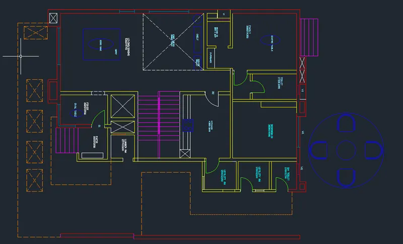
2 Floor plan:
Aim: to draw the floor plan of a building.
Procedure:
- Draw construction lines using "XL-H" and "XL-V".
- Give an offset of 230mm from the vertical to draw the thickness.
- First we draw the Drawing family room:
- Give an offset of 3880mm from the wall thickness and offset of 230mm for the other side.
- Now draw an offset of 300mm as wall thickness from the horizontal construction line.
- Again draw an offset of 4350mm from the 300mm wall thickness for drawing the room.
- Now we draw the toilet:
- Give an offset of 1750mm from the right wall off family room and also offset 150mm to show wall thickness.
- Draw an offset of 250mm from the horizontal construction line for the wall thickness of toilet on outside side.
- Now draw an offset of 3000mm from the wall thickness so that toilet is formed.
- From the offseted line draw 150mm for the wall thickness inside.
- Now we draw the guest bed room:
- Draw an offset from toilet wall at a distance of 3830mm.
- Again offset the wall thickness of 230mm.
- Offset 4500mm from the horizontal wall also offset 230mm from that line.
- Now we draw the DH toilet:
- Take an offset from the guest bedroom wall of distance 1900mm towards the right side.
- Now offset wall thickness 150mm from that line.
- Offset a distance of 1700mm from the the horizontal line and wall thickness of 230mm.
- Also offset wall thickness of 150mm.
- Trim the extra lines using trim tool.
- Now we draw the utility room:
- Take an offset of 2100mm downwards the wall of DH toilet.
- Also offset the wall thickness of 150mm.
- Now we draw the dishwasher utility:
- From the utility wall take an offset of 2150mm downwards and also the wall thickness of 150mm.
- Now we draw the Kitchen:
- From the left wall of dishwasher utility room, take an offset of 4300mm to the left and wall thickness of 230mm.
- From the wall of guest bedroom draw an offset of 3200mm downwards and also wall thickness of 230mm.
- Extend the top wall of kitchen up to a distance of 1462mm excluding the wall thickness.
- Now we draw the cupboard and powder room:
- From the extended line, gave a distance of 1000mm for the cupboard and wall thickness of 150mm.
- Give an offset of 1800mm from the wall and also wall thickness of 230mm.
- Make the above wall of powder room as 150mm.
- Take an offset of 1650mm from that wall to the bottom.
- Now we draw the living/dining:
- Draw an offset of 9710mm from the wall of powder room and also 230mm for the wall thickness.
- Now we draw the foyer:
- Draw an offset from the wall of living room 2000mm to the right and wall thickness of 230mm.
- Now draw the width of room 3220mm and offsetting from the line extended from the living room.
- offset the wall thickness of 150mm.
- Again offset 230mm for the lift wall and extend it to right.
- Now we draw patio:
- From the wall thickness of 230mm draw an offset of 2100mm downwards.
- From the wall of foyer draw an offset of 2150mm and a wall thickness of 150mm on the right side.
- Now we draw lumber room:
- From the wall of portion draw an offset of 1600mm towards backside.
- Offset a wall thickness of 230mm and to the left side give an offset of 150mm as wall thickness.
- Now we draw duct and lift:
- Draw an offset of 500mm from the 150mm wall of lumber room and wall thickness of 230mm.
- Take an offset of 1620mm from the wall for lift.
- Draw the side walls and front walls of 230mm.
- Now we draw stairs:
- Divide the stair room and offset 200mm to two sides by offset from the centre line.
- We draw the first step then offset 300mm upto 11 divisions and rest portion forms landing and draw 10 threads on other side of division.
- Create ducts at front and backside.
- Door sizes given: D1-1000mm,D2-900mm,D3-800mm,D4-750mm,D5-700mm.
- Window sizes given: W1-2700mm,W2-2500mm,W3-900mm,W5-1000mm,W9-800mm.
- Ventilators sizes: V1-800mm,V2-750mm.
- Dimension the all the rooms and wall thickness.
- Insert the text using multi line text with text height as 300mm and style roman.shx.
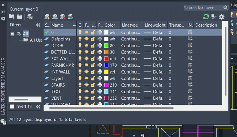
- At last create the layers by clicking on layer tools and assigning each layer with different colours.
Result: the floor plan is drawn:
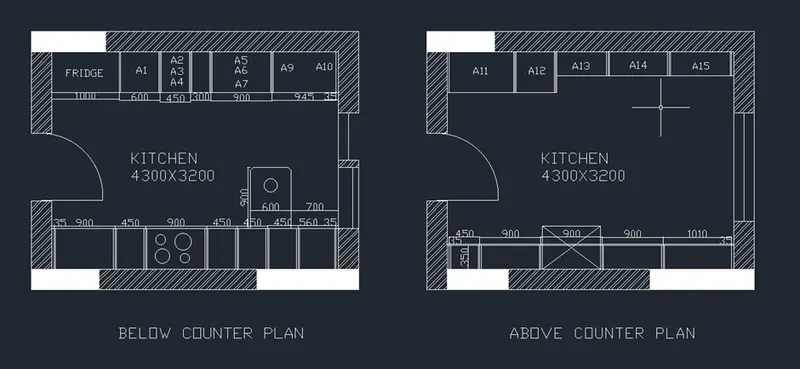
- Kitchen layout:
Aim: to draw the kitchen layout.
Procedure:
- First, we draw the Below counter plan:
- We create a wall by drawing a rectangle of 4300X3200mm and draw offsets of 230mm as wall thickness towards outside.
- Now we draw the Left cabinet and fridge:
- We draw the fridge by drawing a rectangle.
- Take an offset of 1000mm start drawing slab showing cabinet below.
- Offset 600mm for cabinet below for microwave oven and give an offset of 20mm.
- For width of cabinet give 600mm offset,give 20mm inside offset and 10mm offset for thickness.
- From 600mm offset give an offset of 450mm for A1.
- From that give 300mm offset for A2,A3,A4.
- From 300mm offset give another offset of 900mm for A5,A6,A7.
- Draw 35mm offset from the right side front the hinge and give thickness of 20mm.
- Now Drawing the right cabinets and hob:
- Give 35mm offset from the left and create a hinge.
- For width of cabinet give 600mm offset, give 20mm inside offset and 10mm offset for thickness.
- From 35mm give 900mm offset.
- Give an offset of 450mm from the 900mm offset and again offset a distance of 900mm.
- Offset a distance of 450mm three times from the previous offset.
- From the right side offset 35mm for hinge and rest distance will be 630mm which shows the top of cabinet.
- Hob is drawn by rectangle and circle tool in the plan of third cabinet.
- Draw the snack counter by giving offset distance of 700mm from the left side of wall and 900mm from the 600mm width of cabinet and fillet with 10m radius.
- Now draw the above counter plan:
- Copy the wall of the below counter plan.
- Draw the right side counter:
- Draw a width of 350mm from the wall to inside offset 20mm.
- Offset a distance of 35mm from the left side of wall.
- Now offset 450mm for the top of the cabinet.
- Offset 900mm 3 times for next cabinets.
- For the second 900mm offset,draw a rectangle anf froma distance of 1650mm from the left side of wall.draw circle for the chimney.
- Now draw the left side counter:
- From the left side of wall take 35mm offset.
- Now draw 600mm offset as width from the horizontal wall.
- Draw 10mm offset to show the door.
- From the 35mm hinge offset 965mm to the right A11.
- From that offset 600mm for the next cabinet A12.
- Take offset distance of 35mm from the right.
- Rest distance is 2665mm wich is divided into 3 equal parts A13,A14,A15.
- Now offset 20mm on both sides of divisions and also 20mm in front for doors.
- Offset 10mm in backside for thickness.
- Create the Doors,sliding doors and windows:
- Door of size 900mm width and hinge of 20mm.
- Window of width 900mm.
- For the sliding doors take 200mm offset from the window and giving an opening of 900mm.
- Draw the shutters of the sliding door and copy in the other plan also.
- Insert the text by using multiline text of 75mm size and style-roman.shx.
- Dimension all the object using dimension tool bar.
Result: Kitchen layout is drawn.
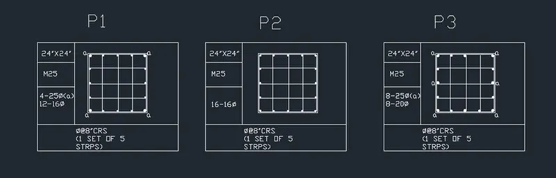
- Column details:
Aim: to draw the column details
Procedure: set the units to imperial as drawing is in feet and inches and set the limits zoom all.
- a) For column P1 size of 24"X24" having 25mm dia reinforcement at 4 corners and 16 mm dia 12 reinforcement bars in between connected by 8mm dia stirrup.
- Now we draw a rectangle of size 24"X24" using the rectangle command using dimensions in the command box.
- By using offset command: give an offset distance of 0.5" which will be the cover of concrete.
- Explode the inner rectangle using explode command.
- Now we draw the reinforcements:
- By using the circle command: selecting tan tan radius circle and give the radius of 0.5".
- As the four corners are having 25mm diameter bars mirror the circles in both the directions.
- Using divide command divide the left line into 4 segments and type "DDPTYPE" to make the points visible.
- Now create a circle with centre radius as 0.31" and place the side of the circle in the centre of the point.
- Copy the two circle and place it in the position of the points.
- Now mirror the 16mm dia bars by vertical mirror plane.
- Repeat the same process for the horizontal line for drawing 16mm bars.
- Connect the bars by 8mm stirrups by using line command.
- Now using the donut command fill the circles.
- Specify the inner dia as 0 and outer dia as 0.8" for the corner reinforcement and 1" for the corner reinforcement and 0.62" for inside reinforcement.
- Mark "a" for in between reinforcement to indicate it as 25mm diameter.
- Create the column to indicate the size of column, grade of concrete and reinforcement details using multiline text with text height as 2" and text style as txt.shx.
- b) For column P2 size of 24"X24" having 16mm dia reinforcement bars connected by 8mm dia stirrup.
- Now we draw a rectangle of size 24"X24" using the rectangle command using dimensions in the command box.
- By using offset command: give an offset distance of 0.5" which will be the cover of concrete.
- Explode the inner rectangle using explode command.
- Now we draw the reinforcements:
- By using the circle command: selecting tan tan radius circle and give the radius of 0.31".
- As the four corners are having 25mm diameter bars mirror the circles in both the directions.
- Using divide command divide the left line into 4 segments and type "DDPTYPE" to make the points visible.
- Copy the circle created such that the end of circle is in centre of the point.
- Mirror the 16mm diameter bars by drawing vertical mirror plane and delete the points created.
- Again divide the horizontal lines into 4 segments and copy the circle and place the side of circle in the centre of the point.
- Connect the bars by 8mm stirrups by using line comand.
- Now using the donut command fill the circles.
- Specify the inner dia as 0 and outer dia as 0.31" specify the centre of the donut and it gets filled.
- Create the column to indicate the size of column,grade of concrete and reinforcement details using multiline text with text height as 2" and text style as txt.shx.
- c) For column P3 size of 24"X24" having 8 bars of 25mm dia and 8 bars of 20mm dia connected by 8mm dia stirrup.
- Now we draw a rectangle of size 24"X24" using the reactangle command using dimensions in the command box.
- By using offset command: give an offset distance of 0.5" which will be the cover of concrete.
- Explode the inner rectangle using explode command.
- Now we draw the reinforcements:
- By using the circle command: selecting tan tan radius circle and give the radius of 0.5".
- As the four corners are having 25mm diameter bars mirror the circles in both the directions.
- Using divide command divide the left line into 4 segments and type "DDPTYPE" to make the points visible.
- Copy the 25mm diameter circle to the middle vertical and horizontal bars.
- Now create a circle of with centre if radius 0.39" and place the side of circle with centre of point.
- Copy the two circle and place it in the position of the rest of the points.
- Mirror the 20mm diameter bars by drawing vertical mirror plane and delete the points created.
- Again, divide the horizontal lines into 4 segments and copy the circle and place the side of circle in the centre of the point.
- Connect the bars by 8mm stirrups by using line command.
- Now using the donut command fill the circles.
- Specify the inner dia as 0 and outer dia as 0.1" for 8 25mm reinforcement and 0.78" for rest of the 8 reinforcement specify the centre of the donut and it gets filled.
- Create the column to indicate the size of column,grade of concrete and reinforcement details using multiline text with text height as 2" and text style as txt.shx.
Result: All three column details are drawn.
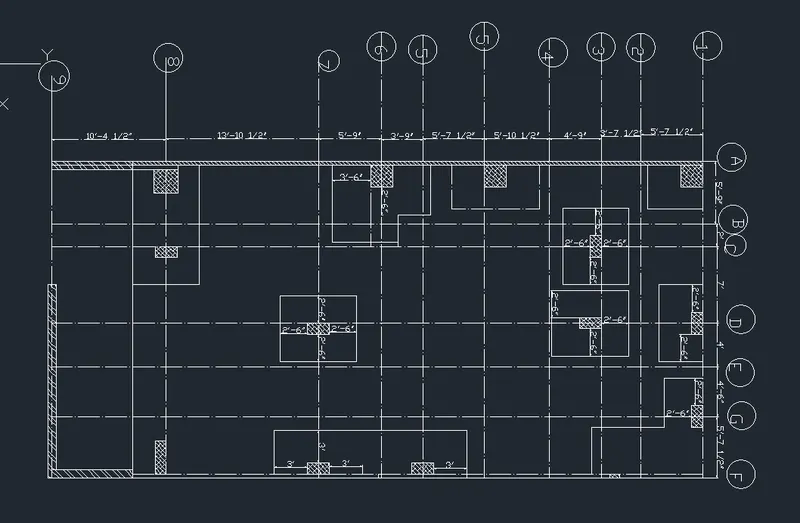
Q5:
Aim: To draw the Raft Layout as shown in the Figure using Autocad.
PROCEDURE :
- first the open the software
- give the command QNEW and press the ENTERE key
- click on imperical templete
- select ADVANCE SETUP
- unit : ARCHITECTURAL , precision :0'-0"
- angle :decimal degree , precision :0.00
- angle measure : East
- angle direction : clockwise
- area : 20*20
- and finished , lets start
- Command : limmax and set the limets
- command : z ( for zoom )
- command :xl
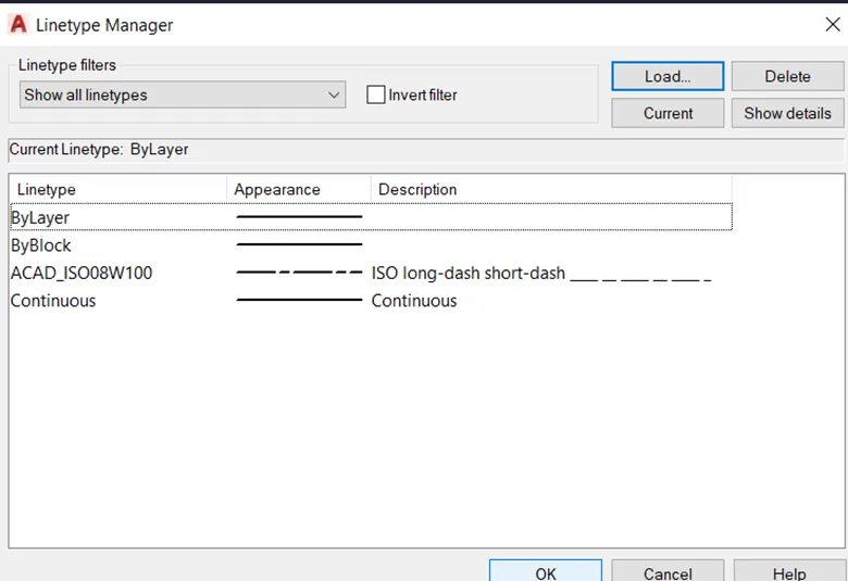
- first go to the line properties
- click on load
- select the Hach line
- press :ENTER
- Command : o (for ofset )
- give the all ofset distence as per the plan
- command :REC ( FOR rectangle )
- rectance for column
- column size used :
- 9",18"
- 24",24"
- 9",24"
- command : hatch
- and give the hatch to the all columns

- command :DIMLIN ( FOR DIMENSION )
- give all dimension to the all columns
- RESULTS :