Creating a Wardrobe detailed drawing, Floor Plan, Kitchen Layout and Column Detail using AutoCad
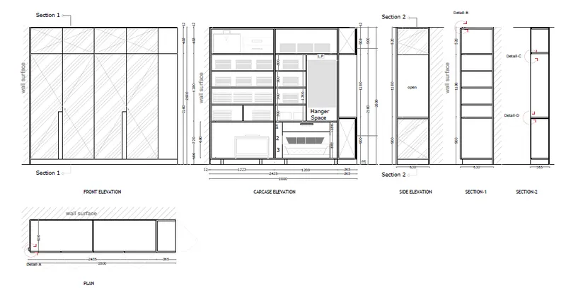
1. Draw the elevation and details of a wardrobe as shown in the Figure below.
INTRODUCTION
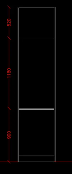
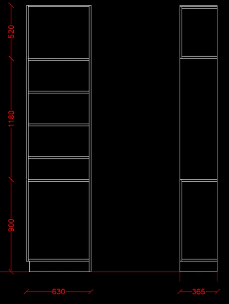
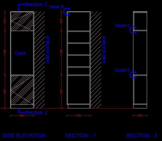
1. The front elevation, carcase elevation, side elevation and two section views for the cabinet are drawn.
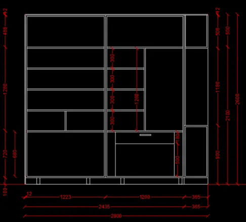
2. The thickness of all shelves is 20mm.
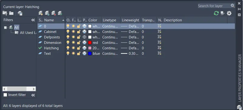
3. Layer
4. All the dimensions are in mm.
PROCEDURE
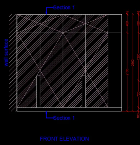
1. Make the following layout with the given dimensions for the front elevation.
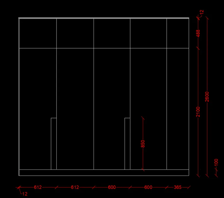
2. Give the hatching for the front doors and wall along with the required text.
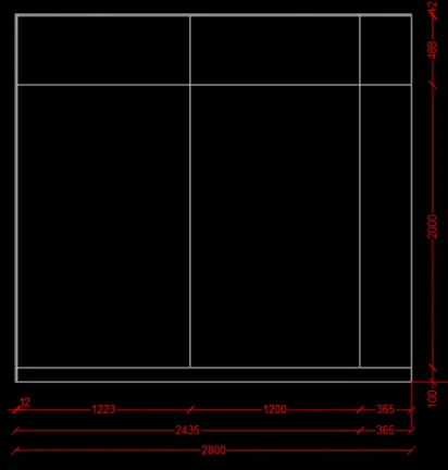
3. Make the following layout for the carcase elevation.
elevation.
4. Make the interior shelves with the following dimensions as shown.
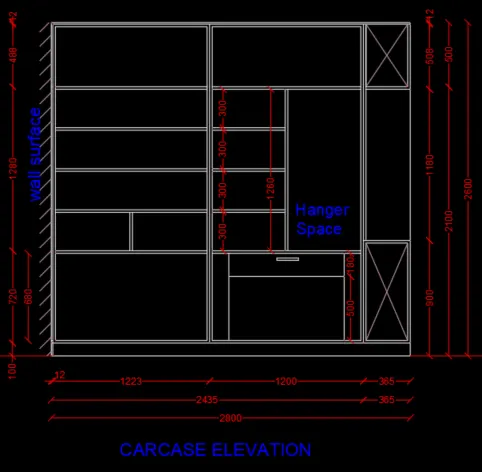
5. Give the hatching and text.
6. Make the following layout for side elevation.
7. Make the following layout the the section 1 and 2.
8. Give the side and section views hatching and text.
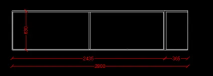
9. Similarly make the plan view.
NOTE : DRAW THE ALL LINES WITH THE THE LINE COMMAND AND USE THE HATCH FOR THE DESIGN ON THE WALL SURFACE AND CHANGEING THE DIMENSION SETTING FOR THE REQURIED DIMENSION STYLE
RESULT: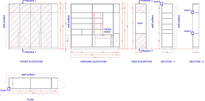
Draw the floor plan as shown in the Figure."`
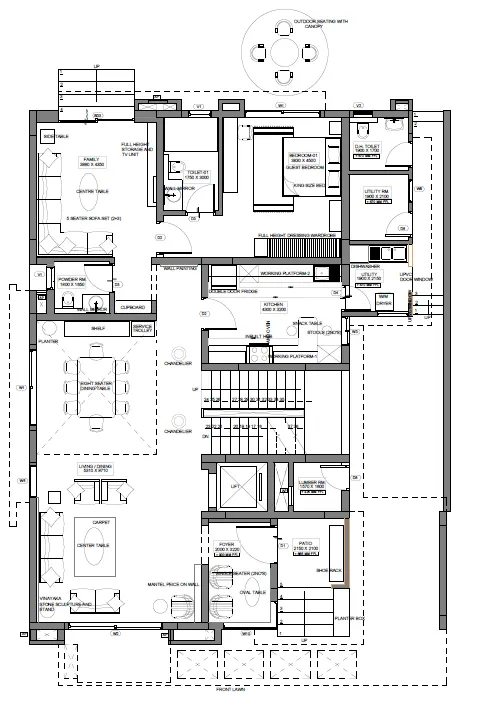
PROCEDURE:DRAW THE ALL LINES WITH THE THE LINE COMMAND AND USE THE HATCH FOR THE DESIGN ON THE WALL SURFACE AND CHANGEING THE DIMENSION SETTING FOR THE REQURIED DIMENSION STYLE
CHANGING THE LINE TYPE FOR SOME LINES CREATING THE DOORS ETC
ADJUSTING SOME DIMENSIONS
RESULT: FINALY FALLOWING ALL THESE STEPS IN A PROCEDURE WE GET REQURIED RESULT
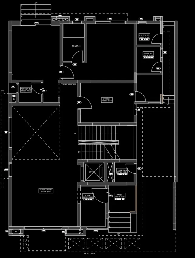
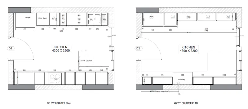
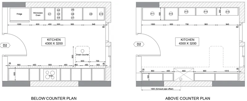
`3. Create the Kitchen Layout as shown in the Figure below.
PROCEDURE
1. Make the following layout as shown.
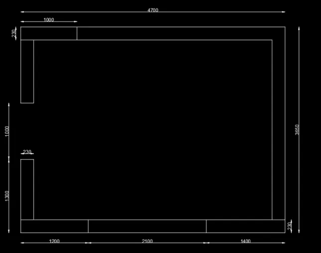
2. Give the hatching for columns and walls. Make the door and windows as shown.
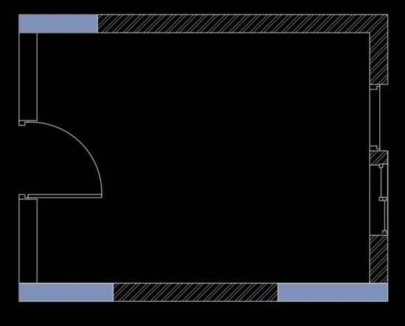
3. Make the furniture as shown.
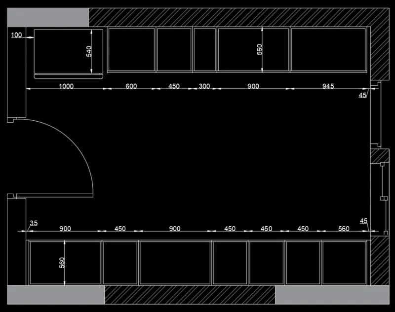
4. Make the snack counter.
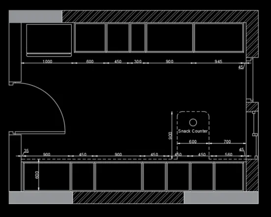
5. Add the text.
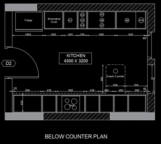
6. Copy the below counter plan and make the required changes to make it into the above counter plan.
(Remove fridge and put a cabinet, make hob into a chimney, reduce the width for cabinets, etc.)
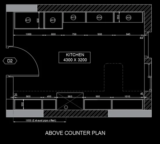
NOTE : DRAW THE ALL LINES WITH THE THE LINE COMMAND AND USE THE HATCH FOR THE DESIGN ON THE WALL SURFACE AND CHANGEING THE DIMENSION SETTING FOR THE REQURIED DIMENSION STYLE
RESULT
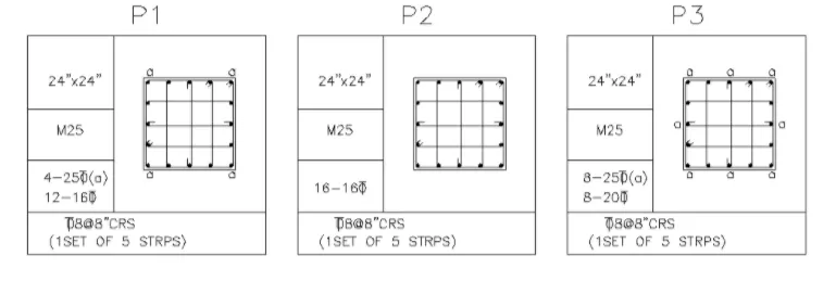
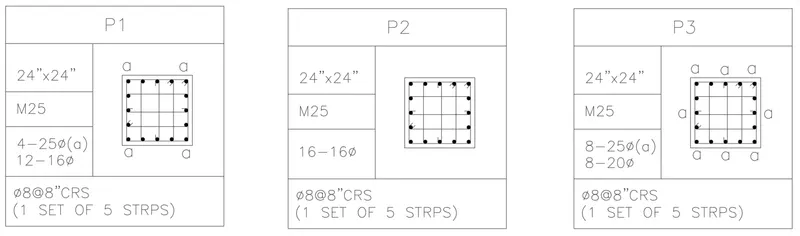
`4. Sketch the column details as shown in Figure. Insert dimensions and text in the figure.
`bbb"PROCEDURE"`
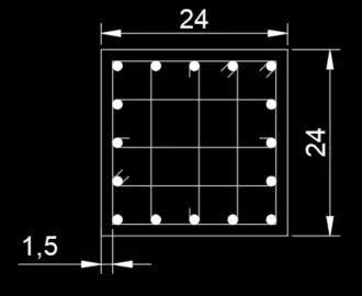
1. Make the column section as shown. (Clear cover is assumed as 1.5 inches)
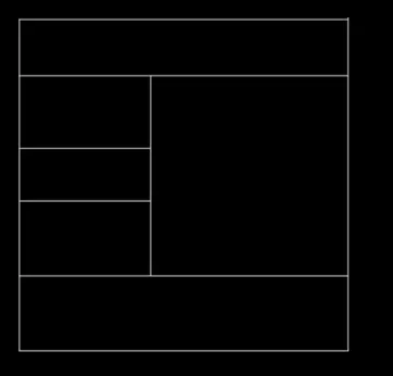
2. Sketch the following table.
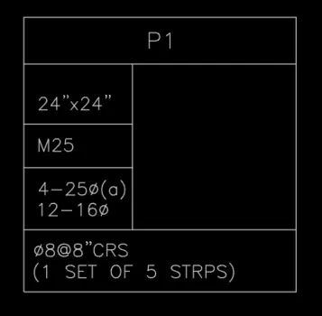
3. Fill in the details for the P1 column.
4. Move the column section into the table.
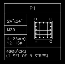
5. Make 2 copies of it and change them accordingly for P2 and P3 columns.
NOTE : DRAW THE ALL LINES WITH THE THE LINE COMMAND AND USE THE HATCH FOR THE DESIGN ON THE WALL SURFACE AND CHANGEING THE DIMENSION SETTING FOR THE REQURIED DIMENSION STYLE
RESULT
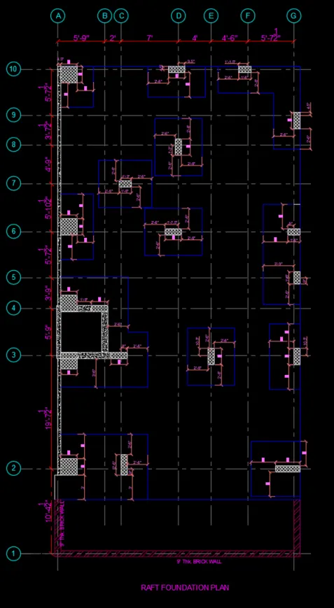
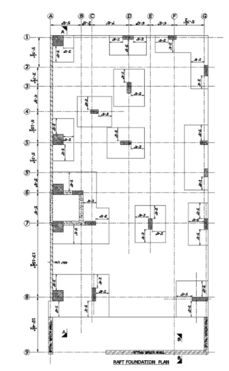
5. Draw the Raft Layout as shown in the Figure
INTRODUCTION
1. The width for all the columns is either 2' or 9"
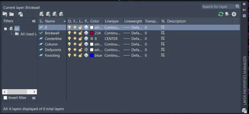
2. Layers:
PROCEDURE
1. Make the grid as shown.
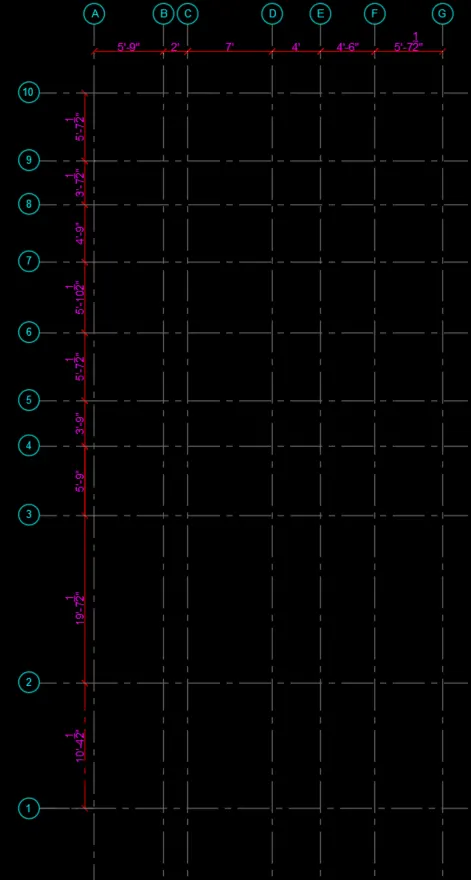
2. Sketch the columns and footings.
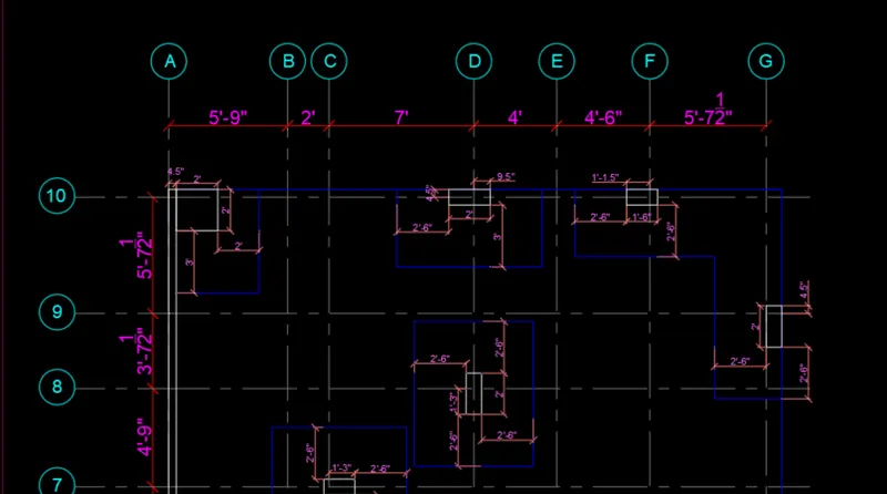
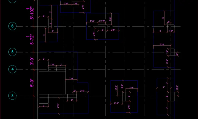
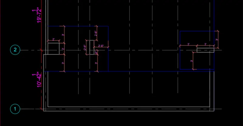
3. Hatch the columns, shear wall, retaining wall, and brick wall.
NOTE : DRAW THE ALL LINES WITH THE THE LINE COMMAND AND USE THE HATCH FOR THE DESIGN ON THE WALL SURFACE AND CHANGEING THE DIMENSION SETTING FOR THE REQURIED DIMENSION STYLE
RESULT