Creating a Wardrobe detailed drawing, Floor Plan, Kitchen Layout and Column Detail using AutoCad
- The elevation and details of a wardrobe:
Aim:
To create the elevation and details of a wardrobe using Auto CAD.
Introduction:
The following commands and tools are used in this Auto CAD drawing,
- Line: It helps to create a line between two points
- Rectangle: It helps to create a four-sided geometry with a desired length and width.
- Offset: It helps to offset an object at a particular distance.
- Move: It helps to move an already existing object from one point to the other by picking a base point.
- Copy: It helps to copy an already existing object from one point to the other by picking a base point.
- Trim: It helps to trim off the extra lines or objects of a selected object which is created while using other tools.
- Break at point: It helps to break the selected object at a single point
- Erase: It helps to erase a selected object.
- Hatch: It helps to hatch a select closed objects in different patterns
- DT: single text: It helps to enter the single line text
- MT: Multi-line text: It helps to type multi line text or paragraphs
- MTEXTED: Text edit: It helps to edit the typed texted.
Note:
- Keep Ortho on and Object snap on which are in the status bar throughout the drawing which helps to find midpoint, center point and so on.
Procedure:
- In command: units
- The drawing units dialog box appears, in that select Decimal as type and precision as 0.00, intersection scale as millimeters and click OK.
- In command: limits
- Specify lower left corner: 0.00,0.00
- Specify upper right corner: 10000,10000
- Enter zoom and enter all in the command.
- Select line command and pick up a random point and move cursor to 90 angle and type 2100 by keeping the cursor at the same angle enter 488, 12 and press enter after each dimension
- Now move cursor to 0 angle and type 12 by keeping the cursor at the same angle enter 12, 1223, 1200, 365 and press enter after each dimension.
- Now move cursor to 270 angle and type 12 by keeping the cursor at the same angle enter 12, 488,2100 and press enter after each dimension
- Select line command and draw a random length of base line immediate under the elevation.
- Select line command. From base line draw horizontal line of height 160mm from the base line.
- Select line command pick the end point of the left vertical first line and join it with the other end.
- Select line command and pick the mid-point of the horizontal top line and connect it to the bottom.
- Select line command and pick the mid-point of the left top line and connect it to the other end.
- Select line command and pick the mid-point of the right top line and connect it to the other end like shown below.
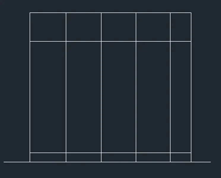
- Select of Offset and give offset distance as 12 and offset the top horizontal line and left vertical line.
- Select line command and pick the end point and mid-point of the 4 doors and draw cross lines on top portion.
- Select Line command and pick the intersection point of the line above the base line and second vertical line from left. Move cursor to the 90 angle and draw a random length line and move it to 180 and enter 100 and join it to the bottom.
- Select circle command and pick a center point and draw a random small circle inside the left side of the third door of the wardrobe part just near the above drawn line.
- Select copy command and select the circle and the lines which drawn earlier and pick a base point and copy it to the third door from the left.
- Enter h and select pattern as ANSI34. Pick the point of the four doors to give hatch as shown below
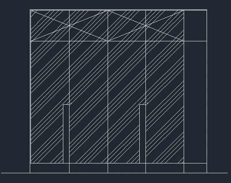
- Select layer properties and create new layers for Dimensions and Text and pick colors like shown below
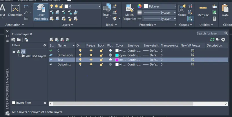
- Change the layer to Dimension and select linear dimension on ribbon and pick the both ends of 12 mm thickness in the top and select continuous dimension and click the next vertical end which gives the dimension 488 and click the perpendicular base point which gives the dimension 2100
- Select linear dimension and select the base point and move cursor to the top and click which gives the dimension as 2600
- Change the layer to text and enter DT and specify the first point in the bottom and give text height as 60 and angle as 0 and types SECTION 1
- Select QLEADER and specify first, second, third point to form a arrow connecting the text.
- Follow the same procedure on top
- Enter DT and specify the first point on the left side exterior area and give text height as 60 and enter angle as 90 and type WALL SURFACE as shown below.
- Enter DT and specify the first point on the bottom and give text height as 70 and give angle as 0 and type FRONT ELEVATION.
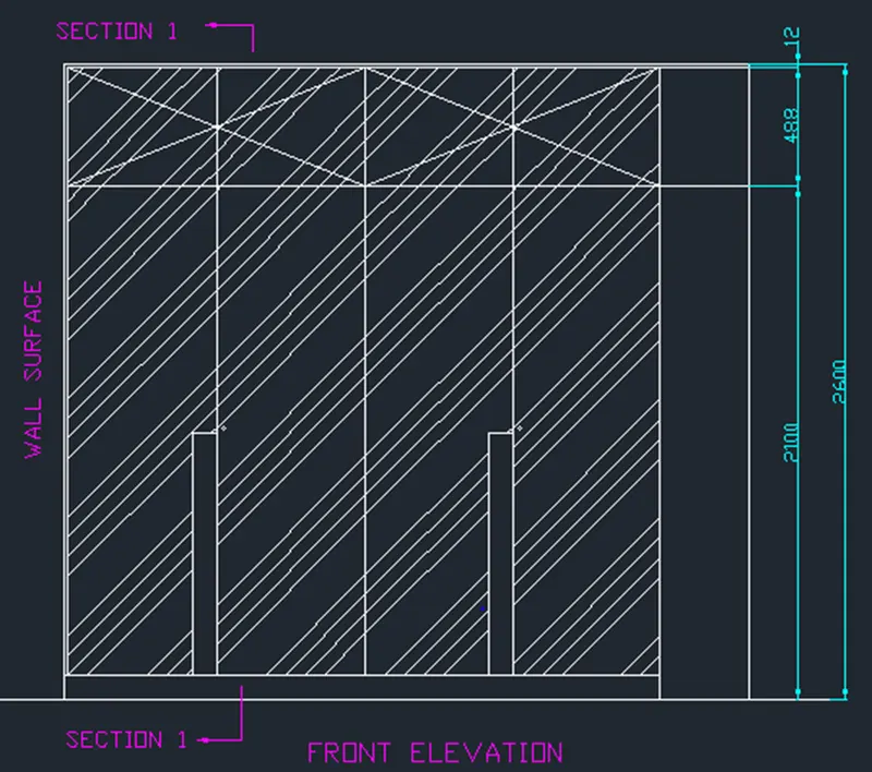
- For CARCASE ELEVATION, select copy command and copy the main lines of the wardrobe which was created above without hatch and place it nearby.
- Select offset and give offset distance as 12 and select the top third line of dimension 488 from the top and create an offset line. Select offset and give offset distance as 300 and create another offset line.
- Follow the same procedure for 3 more times to create offset lines for shelves.
- Select offset and give offset distance as 30 and select the above offset line
- Select offset and give offset distance as 180 and select the above offset line
- Select offset and give offset distance as 250 and select the above offset line
- Select offset and give offset distance as 250 and select the above offset line
- Select offset and give offset distance as 30 and select the above offset line
- Select offset and give offset distance as 100 and select the above offset line
- Enter O and select the base line and give offset distance as 900 and move the cursor up.
- Select offset and give offset distance as 12 and select the above offset line to create another offset line
- Select Trim command and trim the lines outside of wardrobe as show below
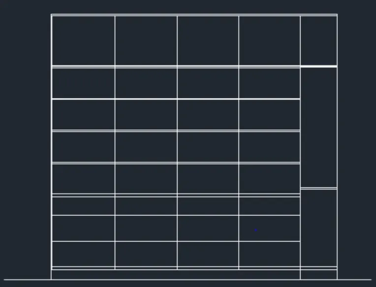
- Select offset command and give offset distance as 12 and select the inner four vertical line and create offset line for each.
- Select the Trim command and trim the lines like shown below
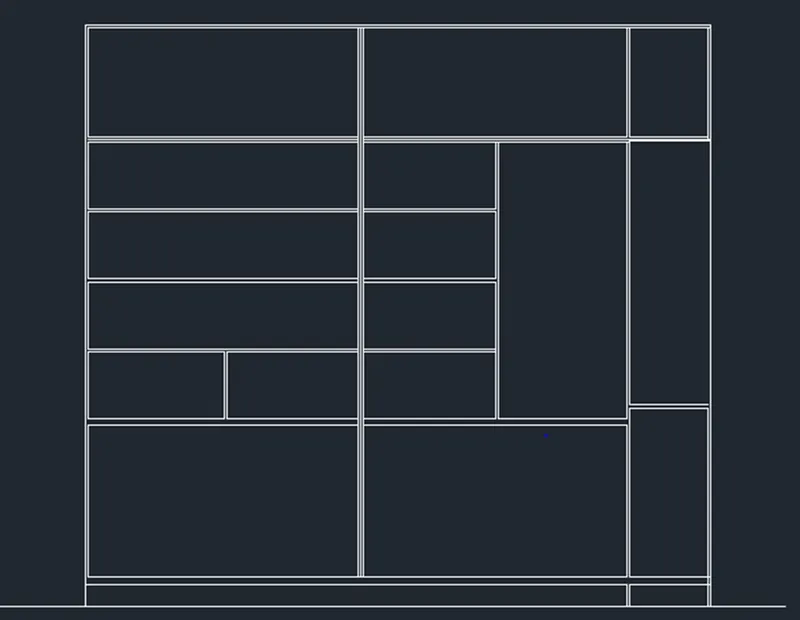
- Select Rectangle command and give dimension, length as 300 and width as 200 to create a rectangle.
- Select copy and click multiple and copy it inside each shelf
- Select rectangle command and create random dimension rec and place it inside the shelves.
- Select Dimension layer and create each dimension by select linear dimension and continuous dimension by click the starting and end points of the lines.
- Change layer to text and select MT and specify starting and end point by give height as 70 and type CARCASE ELEVATION in the bottom and HANGER SPACE as shown below.
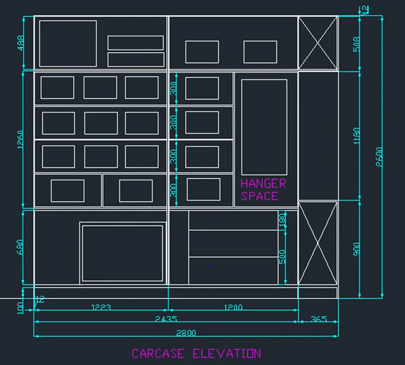
- For Plan Select the line command and select the end point of the vertical line from the front elevation and draw some random dimension lines.
- Select line command and draw horizontal line till it meats the right last line.
- Select offset and pick the above line and offset it with dimension of 630
- Select offset and select the rectangular lines and give offset distance as 12 and offset inside as shown below
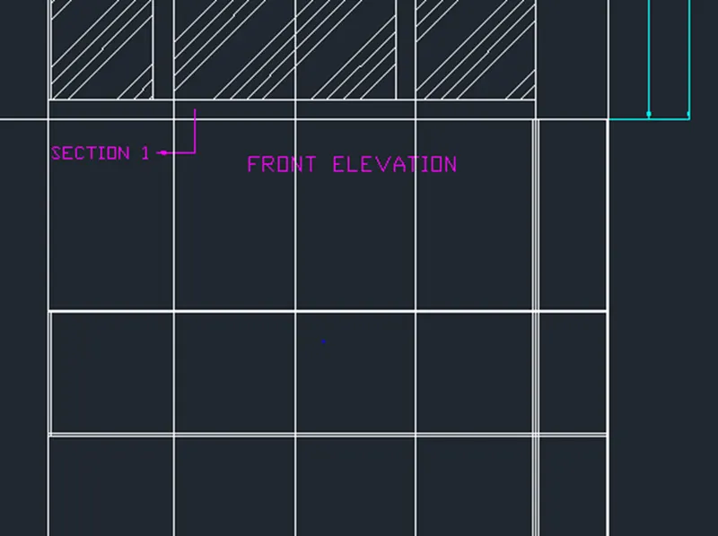
- Select Trim command and select the object as a whole and trim the lines as shown below
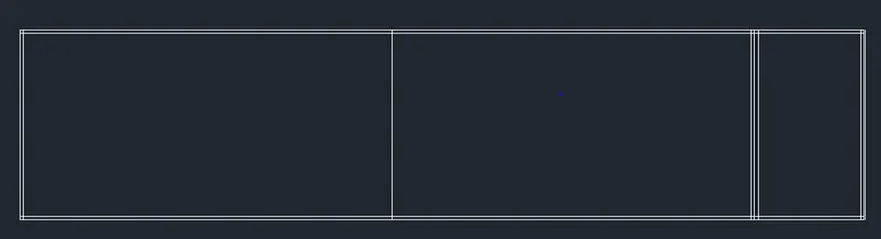
- Select offset and give offset distance as 12 and select the middle line and offset on both sides.
- Enter f and give radius as 0 and click multiple and select all the two corner lines to fillet.
- Select Circle command and create a circle randomly
- Select line command and create two arrows facing each other with some distance
- Select trim command and trim the inside line between the arrows
- Enter b, which opens a block definition dialog box. Give name as moment and select the object, pick a point and click ok to create this a s block
- Go the layer properties to create new layer for the Torque and give a color
- Select copy command and copy the block and place it near the left bottom end of the wardrobe
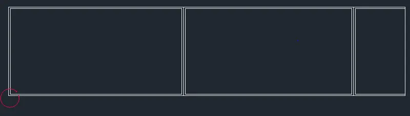
- Select dimension layer and give dimensions by picking start and end points of the line.
- Select Text layer and enter DT and give angle as 0 and text height as 70 and type WALL SURFACE, Detail A, PLAN.
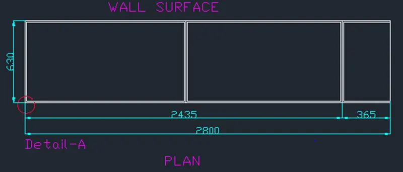
- To draw SIDE ELEVATION, SECTION-1 and SECTION-2, Select line command and extend the horizontal line from the CARCASE ELEVATION as shown below
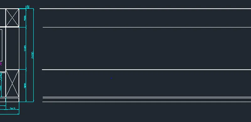
- Select line command and draw a line connecting the top and bottom line
- Select offset and give offset distance as 630
- Select offset and give offset distance as 12 and create offset line inside on both side for SIDE ELEVATION
- Select copy command and select above created lines and paste it near it for SECTION 1
- Select line command and draw a line connecting the top and bottom line for section 2
- Select offset and give offset distance as 365 and select the above created line
- Select offset and give offset distance as 12 and select the above created line and create offset lines inside it
- Select line command and extend the line of wardrobe center shelves from CARCASE ELEVATION to SECTION 1 as shown below
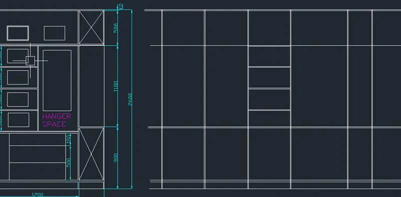
- Select Trim command and Trim all the lines in-between the sections and off set lines
- Select hatch command and hatch the top and bottom portion of SIDE ELEVATION
- Select copy and copy the Torque and place it in top left corner of SECTION-1 and top and bottom torque portion of section-2
- Change the layer to Text and enter co and select text from earlier created text and paste it on respective space
- Change the layer to Dimension and create the dimensions as shown below
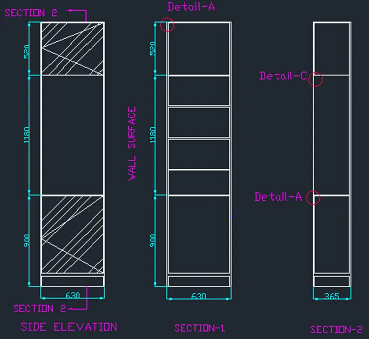
Result:
The result is obtained from the above procedure.
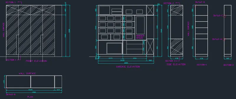
- The floor plan:
Aim:
To create the floor plan using Auto CAD.
Introduction:
The following commands and tools are used in this Auto CAD drawing,
- Line: It helps to create a line between two points
- Rectangle: It helps to create a four-sided geometry with a desired length and width.
- Offset: It helps to offset an object at a particular distance.
- Move: It helps to move an already existing object from one point to the other by picking a base point.
- Copy: It helps to copy an already existing object from one point to the other by picking a base point.
- Trim: It helps to trim off the extra lines or objects of a selected object which is created while using other tools.
- Break at point: It helps to break the selected object at a single point
- Erase: It helps to erase a selected object.
- Hatch: It helps to hatch a select closed objects in different patterns
- DT: single text: It helps to enter the single line text
- MT: Multi-line text: It helps to type multi line text or paragraphs
- MTEXTED: Text edit: It helps to edit the typed texted.
- XLine: It helps to create infinite vertical and horizontal line
- LT: Line type: It helps to change the line type and scale
- Array: It helps to copy an object in rows and column at desired space
Note:
- Keep Ortho on and Object snap on which are in the status bar throughout the drawing which helps to find midpoint, center point and so on.
Procedure:
- In command: units
- The drawing units dialog box appears, in that select Decimal as type and precision as 0.00, intersection scale as millimeters and click OK.
- In command: limits
- Specify lower left corner: 0.00,0.00
- Specify upper right corner: 50000,50000
- Enter zoom and enter all in the command.
- Enter XL and choose horizontal option and place it randomly.
- Enter XL and choose vertical option and place it randomly.
- Select offset and give offset distance as 230 and offset outside the both horizontal and vertical line
- Select offset and give offset distance as 5310 and offset on right
- Select offset and give offset distance as 230 and create offset line
- Select offset and give offset distance as 2000 by selecting the previously created line
- Select offset and give offset distance as 230 and create offset line
- Select offset and give offset distance as 2150 and select the previously created line and create offset line
- Select offset and give offset distance as 230 and create offset line
- Select offset and give offset distance as 3220 and select inner wall of the base line and create offset line
- Select offset and give offset distance as 230 and select the previously created line and create offset line
- Select offset and give offset distance as 1600 and select the previously created line and create offset line
- Select offset and give offset distance as 230 and select the previously created line and create offset line
- Select offset and give offset distance as 9710 and select inner wall of the base line and create offset line
- Select offset and give offset distance as 230 and offset on top
- Select offset and give offset distance as 1650 and select the previously created line and create offset line
- Select offset and give offset distance as 230 and offset on top
- Select offset and give offset distance as 1750 and select the previously created line and create offset line
- Select offset and give offset distance as 230
- Select offset and give offset distance as 3830 and select the previously created line and create offset line
- Select offset and give offset distance as 230
- Select offset and give offset distance as 1900 and select the previously created line and create offset line
- Select offset and give offset distance as 150
- Select offset and give offset distance as 976.71 and select the previously created line and create offset line
- Select offset and give offset distance as 230
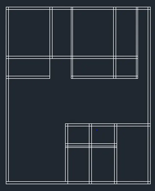
- Select Trim tool and trim all the extra line other than the plan which is shown below
- Select offset command and select the right inner wall of Lumber RM and give offset distance as 1570
- Select offset and give offset distance as 150
- Select rectangle tool and create random dimension inside the Lift area
- Select line tool and diagonally connect the lines in lift room and AP
- In the living create a window length of 3048 in the middle of the base wall using line command
- In the Foyer create a window length of 1754 on bottom and length of 1144 on right-side using line command.
- Select rectangle command and draw a random rectangle for left AP of having wall thickness of 230 and 150
- Same procedure for right side AP with little longer length.
- Select rectangle command and give dimension, length as 1200 and width as 875 and create a rectangle outside the plan
- Select the object and enter LT to change the line type to ACAD_ISO02W100
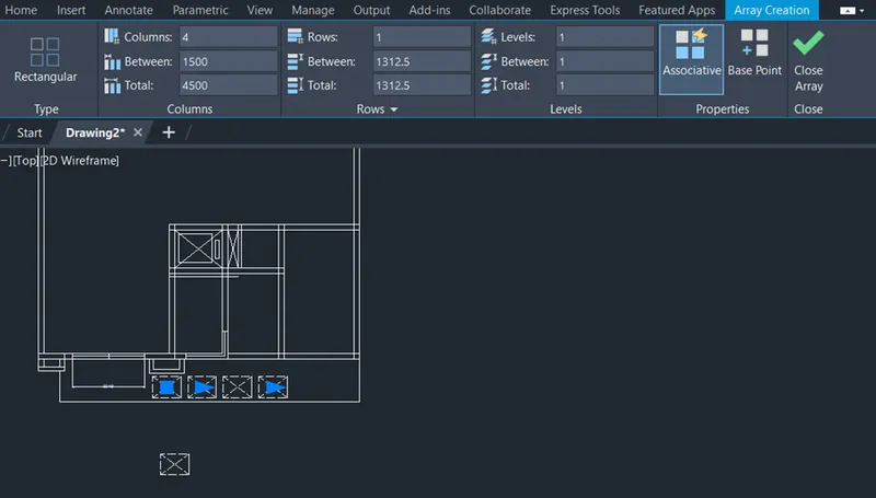
- Select copy command and paste it below right AP and select array option for following details
- Select line command and create the lift room front wall thickness to 230
- Select offset and create Patio of dimension 2150x2100
- Enter Tr and select object as a whole and create opening for steps.
- Select line command and pick the middle point of the opening and join it to the other side.
- Select offset and give offset distance as 400 and offset 4 times to create steps
- Select line command to draw the planter box and to draw front lawn.
- Enter LT to change the line type to Dot lines as mentioned earlier
- Select line command and create powder room of dimension 1800x1650 and window v1 of length 904
- Using line command and circle command create a circle out side the plan and select trim command to trim the circle
- Select copy command and pick a base point and copy it in the powder room and Foyer
- For creating Kitchen, select offset and select the Guest bed room outer wall and give offset distance as 3200
- Select kitchen right side vertical wall and give offset distance as 4300
- Select the door which created earlier and select rotate to rotate it to o angle and copy it to the kitchen wall and utility room
- Select trim to trim the extra lines
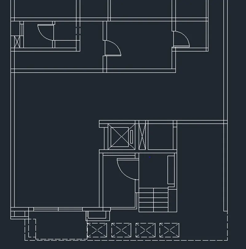
- For creating steps in the middle of the plan select the inner wall at the right side near the area and select offset command and give offset distance as 1202
- Select offset and give offset distance as 300 and create steps till the end of the kitchen wall.
- Select line command and draw middle line and select offset and give offset distance as 150 and offset on both sides of the middle line
- Select trim and trim all the extra lines
- Select rectangle command and draw a random rectangle inside it
- Select line command and draw lines in-between up and downside steps and create Dotted lines going to properties ang changing the line type.
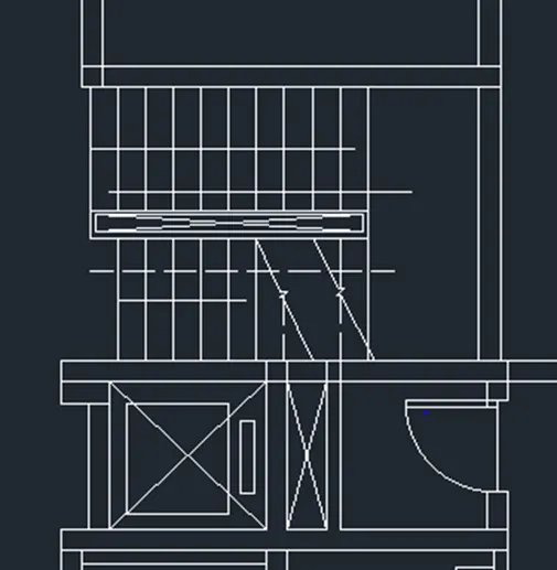
- Create jog lines using line commands like shown below
- Select offset and the inner wall of the utility room then give offset distance as 2150
- Select offset and give distance as 150 and select the previously created offset line
- Select offset and give distance as 2100 and select the previously created offset line
- Select offset and give distance as 150 and select the previously created offset line
- Select offset and give distance as 1700 and select the previously created offset line
- Using line command draw windows
- Select trim to trim the extra lines
- Select copy and copy the Door created earlier to copy it in toilet and family room
- Select right corner inner wall and give offset distance as 1700
- Select the previously created line and give offset distance as 150
- Select the previously created line and give offset distance as 2100
- Select the previously created line and give offset distance as 150
- Select the previously created line and give offset distance as 2150
- Select copy and copy the Door created earlier to copy it in toilet and 2 utility rooms
- Select line command and draw window in those rooms
- Select offset and give offset and give offset distance as 300 to draw steps in the outer space
- Select line command and draw outer line and right click to properties and change the line type to dotted and scale as 1
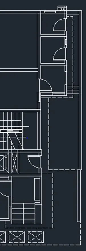
- Select line command to draw all outline dot lines by going to property and to draw windows
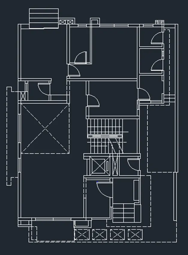
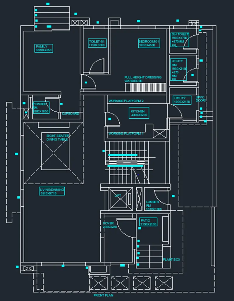
- Select DT and MT to create text which is shown in the result.
Result:
The result is obtained from the above procedure.
- The kitchen layout:
Aim:
To create the kitchen layout using Auto CAD.
Introduction:
The following commands and tools are used in this Auto CAD drawing,
- Line: It helps to create a line between two points
- Rectangle: It helps to create a four-sided geometry with a desired length and width.
- Offset: It helps to offset an object at a particular distance.
- Move: It helps to move an already existing object from one point to the other by picking a base point.
- Copy: It helps to copy an already existing object from one point to the other by picking a base point.
- Trim: It helps to trim off the extra lines or objects of a selected object which is created while using other tools.
- Break at point: It helps to break the selected object at a single point
- Erase: It helps to erase a selected object.
- Hatch: It helps to hatch a select closed objects in different patterns
- DT: single text: It helps to enter the single line text
- MT: Multi-line text: It helps to type multi line text or paragraphs
- MTEXTED: Text edit: It helps to edit the typed texted.
Note:
- Keep Ortho on and Object snap on which are in the status bar throughout the drawing which helps to find midpoint, center point and so on.
Procedure:
- In command: units
- The drawing units dialog box appears, in that select Decimal as type and precision as 0.00, intersection scale as millimeters and click OK.
- In command: limits
- Specify lower left corner: 0.00,0.00
- Specify upper right corner: 10000,10000
- Enter zoom and enter all in the command.
- Select rectangle command and type dimension, length as 4300, width as 3200 and create 2 rectangles as Below counter plan and Above counter plan
- Select offset and give dimension as 230 and offset outside the rectangle on both.
- Select Break at point and break the lines at all the 4 corners of both rectangles.
- In both rectangles select the top and bottom horizontal lines, enter o and give offset distance as 600, 600, 600and 350 for the below- above counter plan respectively
- Select Break at point and break the lines at all the intersection point between horizontal offset and wall on both rectangles.
- Enter O and select the bottom left vertical line which used for break at point and give offset distance as 35 at below counter plan
- Enter O and select the previously created offset line and give offset distance as 900
- Enter O and select the previously created offset line and give offset distance as 450
- Enter O and select the previously created offset line and give offset distance as 900
- Enter O and select the previously created offset line and give offset distance as 450
- Enter O and select the previously created offset line and give offset distance as 450
- Enter O and select the previously created offset line and give offset distance as 450
- Enter O and select the previously created offset line and give offset distance as 560
- Enter O and select the previously created offset line and give offset distance as 35
- Enter O and select the previously created offset line and give offset distance as 900
- Enter O and select the other half line on right broken line and give offset distance as 700
- Enter O and select the previously created offset line and give offset distance as 600 like shown below
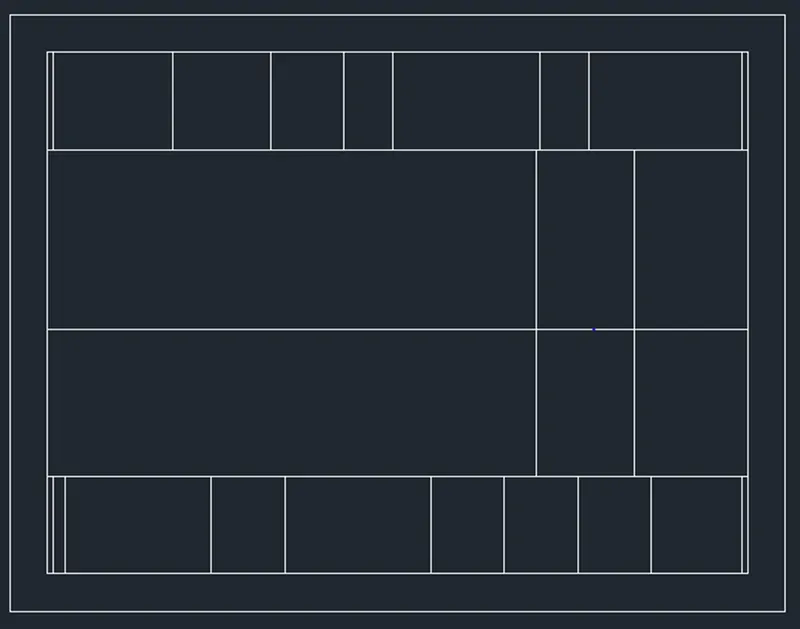
- Enter O and select the top right vertical line which used for break at point and give offset distance as 35
- Enter O and select the previously created offset line and give offset distance as 945
- Enter O and select the previously created offset line and give offset distance as 300
- Enter O and select the previously created offset line and give offset distance as 900
- Enter O and select the previously created offset line and give offset distance as 300
- Enter O and select the previously created offset line and give offset distance as 450
- Enter O and select the previously created offset line and give offset distance as 600
- Enter O and select the previously created offset line and give offset distance as 735
- Enter O and select the previously created offset line and give offset distance as 35
- Enter O and select the bottom left vertical line which used for break at point and give offset distance as 35 at above counter plan
- Enter O and select the previously created offset line and give offset distance as 450
- Enter O and select the previously created offset line and give offset distance as 900
- Enter O and select the previously created offset line and give offset distance as 35
- Enter O and select the previously created offset line and give offset distance as 900
- Enter O and select the previously created offset line and give offset distance as 35
- Enter O and select the previously created offset line and give offset distance as 900
- Enter O and select the previously created offset line and give offset distance as 1010
- On top select the top left vertical line which used for break at point and give offset distance as 35 at above counter plan
- Enter O and select the previously created offset line and give offset distance as 965
- Enter O and select the previously created offset line and give offset distance as 600
- Enter O and select the previously created offset line and give offset distance as 865 and often for 2 more times
- Enter O and select the top horizontal line and give offset distance as 350 as shown below
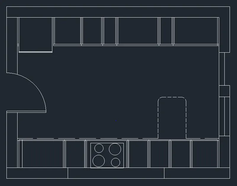
- Select line command and create a door outside the plan and copy it in middle point of both the plans
- In both counter plans select all the inner lines and give offset distance as 30 on both sides of the lines
- Select Trim and trim all the excess lines in the below counter plan
- Select the snack counter lines and change its line type to dotted line by right clicking to open the properties
- Using line command create windows as shown below
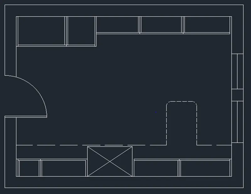
- Select the copy command and select the windows and dotted lines from snack counter and pick the base point and copy it to the above counter plan
- Select trim and select whole object and trim all the excess lines as shown below
- Select layer properties and create layers for text and Dimension
- After selecting text layer
- Enter Dt for single line text and MT for multi-layer text.
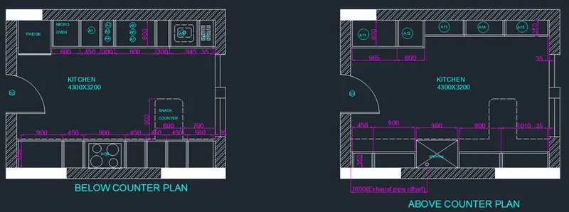
- Select Dimension layer and select linear and continuous dimension for respective length of dimension
Result:
- The result is obtained from the above procedure.
- The column details:
Aim:
To create the column details using Auto CAD.
Introduction:
The following commands and tools are used in this Auto CAD drawing,
- Line: It helps to create a line between two points
- Rectangle: It helps to create a four-sided geometry with a desired length and width.
- Offset: It helps to offset an object at a particular distance.
- Move: It helps to move an already existing object from one point to the other by picking a base point.
- Copy: It helps to copy an already existing object from one point to the other by picking a base point.
- Trim: It helps to trim off the extra lines or objects of a selected object which is created while using other tools.
- Break at point: It helps to break the selected object at a single point
- Erase: It helps to erase a selected object.
- Hatch: It helps to hatch a select closed objects in different patterns
- DT: single text: It helps to enter the single line text
- MT: Multi-line text: It helps to type multi line text or paragraphs
- MTEXTED: Text edit: It helps to edit the typed texted.
Note:
- Keep Ortho on and Object snap on which are in the status bar throughout the drawing which helps to find midpoint, center point and so on.
Procedure:
- In command: units
- The drawing units dialog box appears, in that select Decimal as type and precision as 0.00, intersection scale as millimeters and click OK.
- In command: limits
- Specify lower left corner: 0’.0.0”,0’.0.0”
- Specify upper right corner: 50’,50’
- Enter zoom and enter all in the command.
- Select Rectangle command and give dimension length as 24” and width as 24’
- Select offset and give offset distance as 1” and select the square
- Select line command and pick the mid-point of the inner square and draw 2 perpendicular lines
- Select line command and pick mid- point of the midpoint and draw 2 lines on both sides
- Select circle command and draw a circle of diameter 1” outside of detail
- Select copy command and select the circle and press multiple and place it in 4 inside the 4 corners of the inner square as shown below
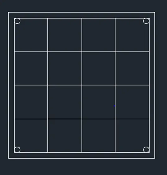
- Select copy and select all the lines of P1 and click multiple and paste it 2 times near it as P2, P3.
- Select circle command and select diameter and create 2 more circles of diameter 20 and 16mm.
- Select 12no. of 16mm Ø circle and it in the sides of the square other than corner
- Select line command draw lines connecting circles and lines
- Select copy and click multiple and select the 16mm Ø circle and copy it in the sides and corners of the square of P2 by the tangent of the circle touching the lines.
- Select copy and click multiple and select the 25mm Ø circle and copy it corners of the square of P3 by the tangent of the circle touching the lines.
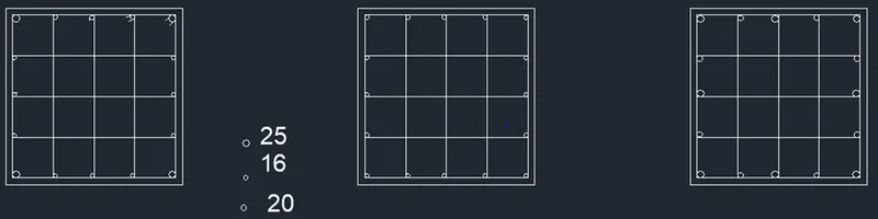
- Select copy and click multiple and select the 25mm Ø circle and copy it in the corners and mid lines of the square of P3 by the tangent of the circle touching the lines.
- Select copy and click multiple and select the 20mm Ø circle and copy it the mid lines of the of the midlines of the sides of square P3 by the tangent of the circle touching the lines.
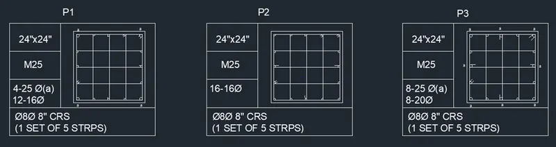
- Select line command and in some bars extend the lines around the circle but picking the tangent point of the circle in P1, P2, P3.
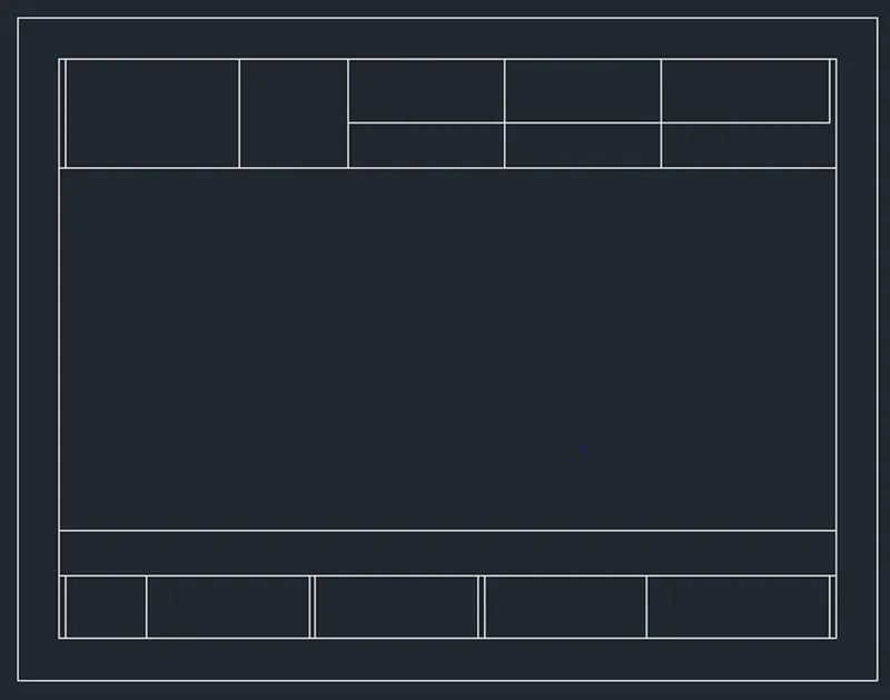
- Select rectangle command and create a random rectangle around the column details
- Select line command draw table by picking the mid-points
- Select copy command and select the table and click multiple and paste it to P2 and P3.
- Select DT for single text by giving the text height and angle as 0
- Select MT for multi text by clicking the starting and end point
Result:
- The result is obtained from the above procedure.
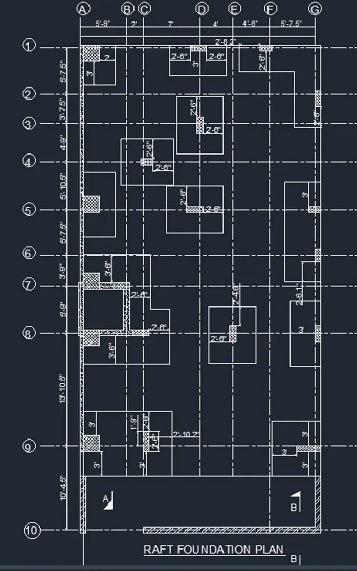
- The raft layout:
Aim:
To create the raft layout using Auto CAD.
Introduction:
The following commands and tools are used in this Auto CAD drawing,
- Line: It helps to create a line between two points
- Rectangle: It helps to create a four-sided geometry with a desired length and width.
- Offset: It helps to offset an object at a particular distance.
- Move: It helps to move an already existing object from one point to the other by picking a base point.
- Copy: It helps to copy an already existing object from one point to the other by picking a base point.
- Trim: It helps to trim off the extra lines or objects of a selected object which is created while using other tools.
- Break at point: It helps to break the selected object at a single point
- Erase: It helps to erase a selected object.
- Hatch: It helps to hatch a select closed objects in different patterns
- DT: single text: It helps to enter the single line text
- MT: Multi-line text: It helps to type multi line text or paragraphs
- MTEXTED: Text edit: It helps to edit the typed texted.
Note:
- Keep Ortho on and Object snap on which are in the status bar throughout the drawing which helps to find midpoint, center point and so on.
Procedure:
- In command: units
- The drawing units dialog box appears, in that select Decimal as type and precision as 0.00, intersection scale as millimeters and click OK.
- In command: limits
- Specify lower left corner: 0’.00”,0’.00”
- Specify upper right corner: 50’,50’
- Enter zoom and enter all in the command.
- Select rectangle command and pick a point and give dimension as 29’7.4” and width as 60’0.1”
- Enter xl and select vertical line and place it on the left vertical length of the rectangle.
- Enter o and select the above line and give offset distance as 5’9”
- Enter o and select the above line and give offset distance as 2’
- Enter o and select the above line and give offset distance as 7’
- Enter o and select the above line and give offset distance as 4’
- Enter xl and select horizontal line and place it in the top horizontal length of the rectangle as temporary line
- Enter o and select the above line and give offset distance as 4’5”
- Delete the first horizontal xl
- Enter o and select the above line and give offset distance as 4’6”
- Enter o and select the above line and give offset distance as 3’7.5”
- Enter o and select the above line and give offset distance as 10’7.5”
- Enter o and select the above line and give offset distance as 5’7.5”
- Enter o and select the above line and give offset distance as 3’9”
- Enter o and select the above line and give offset distance as 13’10.5”
- Enter o and select the above line and give offset distance as 10’4.5”
- Select all xl and select line type in the property and change it to ACAD_ISO08W100 like shown below
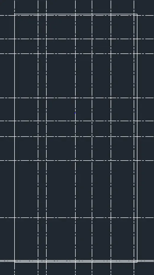
- Enter rec and create a temporary rectangle outside the first rectangle
- Enter tr and select all the object and trim the line outside the outer rectangle and delete the outer rectangle
- Using DT and name each vertical xl from A to G and name each horizontal xl from 1 to 10
- Enter O and select the first vertical line and give offset distance as4.3” and create an offset
- Change the above created line property to by layer
- Enter rec and pick the top end point of the second vertical line and give dimension, length as 4’ and width as 5’
- Enter rec and pick the same starting point and give dimension as 2’ and 2’
- Select line command and pick the starting point as the end of the above drawn top right end of the rectangle move cursor to 0 angle and enter 6’8”
- Move cursor to 270 angle and enter 3’9”
- Move cursor to 0 angle and enter 7’
- Move cursor to 90 angle and enter 3’9”
- Enter L and pick the intersection point od D and top length of rectangle and move cursor to the left and enter 1’2.5”
- Enter L and pick the intersection point of D and top length of rectangle and move cursor to the right and enter 9.6”
- Move cursor to 270 angle and enter 9”
- Move cursor to 0 angle and enter 2’
- Move cursor to 90 angle and enter 9”
- Select line command and pick the starting point as the end of the above drawn top right end of the rectangle move cursor to 0 angle and enter 1’7”
- Move cursor to 270 angle and enter 3’3”
- Move cursor to 0 angle and enter 6’9”
- Move cursor to 270 angle and enter 6’10.5”
- Move cursor to 0 angle and enter 3’3”
- Enter L and pick the intersection point of F and top length of rectangle and move cursor to the left and enter 1’1.5”
- Enter L and pick the intersection point of F and top length of rectangle and move cursor to the right and enter 4.5”
- Move cursor to 270 angle and enter 9”
- Move cursor to 180 angle and enter 1’6”
- Move cursor to 90 angle and enter 9”
- Enter L and pick the intersection point of 2 and top right width of rectangle and move cursor to the top and enter 4.5”
- Enter L and pick the intersection point of 2 and top right width of rectangle and move cursor to the bottom and enter 4.5”
- Move cursor to 180 angle and enter 9”
- Move cursor to 270 angle and enter 2’
- Move cursor to 0 angle and enter 9”
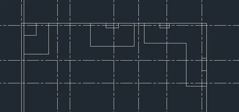
- Select L and pick intersection of 3 and D move left and enter 2’10.5”
- Move cursor to the top and enter 3’3”
- Move cursor to the right and enter 5’9” and click close
- Select L and click same intersection point and move cursor down and enter 1’3”
- Move cursor to the left and enter 4.5”
- Move cursor to the top and enter 2’
- Move cursor to the right and enter9”
- Move cursor to the bottom and enter 2’ and join the rectangle
- Select L and pick intersection of 4 and C move top and enter 2’10.5”
- Move cursor to the left and enter 2’.9”
- Move cursor to the bottom and enter 5’9”
- Move cursor to the right and enter 6’6”
- Move cursor to the top and enter 5’9”
- Move cursor to the left and enter 3’.9”
- Select L and pick the same intersection and move top and enter 4.5”
- Move cursor to the right and enter 1’3”
- Move cursor to the bottom and enter 9”
- Move cursor to the left and enter 1’.6”
- Move cursor to the top and enter 9” and join the rectangle
- Select L and pick intersection of 5 and vertical offset line move top and enter 4’7.5”
- Move cursor to the right and enter 4’
- Move cursor to the bottom and enter 8’
- Move cursor to the left and enter 4’ and join the rectangle
- Select L and pick the same intersection and move top and enter 1’7.5”
- Move cursor to the right and enter 2’
- Move cursor to the bottom and enter 2’
- Join it to the vertical line
- Select L and pick intersection of 5 and D move top and enter 2’10.5”
- Move cursor to the right and enter 4’1.5”
- Move cursor to the bottom and enter 5’9”
- Move cursor to the left and enter 7’
- Move cursor to the top and enter 5’9” and join the rectangle
- Select L and pick the same intersection and move top and enter 4.5”
- Move cursor to the left and enter 1’7.5”
- Move cursor to the bottom and enter 9”
- Move cursor to the right and enter 2’
- Move cursor to the top and enter 9” and join the rectangle
- Select L and pick intersection of 5 and the right side of the rectangle line and move top and enter 3’4.5”
- Move cursor to the left and enter 4’6”
- Move cursor to the bottom and enter 12’3.1”
- Move cursor to the right and enter 4’6” and join the rectangle
- Select L and pick intersection of 5 and the right side of the rectangle line and move top and enter 4.5”
- Move cursor to the left and enter 1’6”
- Move cursor to the bottom and enter 9”
- Join the rectangle
- Select L and pick intersection of 6 and the second vertical line from the left and move top and enter 1.5”
- Move cursor to the right and enter 8’3”
- Move cursor to the bottom and enter 6’9”
- Move cursor to the right and enter 2’4.5”
- Move cursor to the bottom and enter 6’9”
- Join it to the line
- Select L and pick intersection of 7 and the left side of the rectangle line and move top and enter 1’7.5”
- Move cursor to the right and enter 2’
- Move cursor to the bottom and enter 1’3”
- Move cursor to the right and enter 3’9”
- Move cursor to the bottom and enter 5’9”
- Move cursor to the right and enter 2’4.5”
- Move cursor to the bottom and enter 9”
- Move cursor to the left and enter 6’1.5”
- Move cursor to the bottom and enter 1’3”
- Move cursor to the left and enter 2’
- Select L and pick intersection of 8 and E move top and enter 2’10.5”
- Move cursor to the top and enter 10.4”
- Move cursor to the right and enter 4.5”
- Move cursor to the bottom and enter 2’
- Move cursor to the left and enter 9”
- Move cursor to the top and enter 2’
- Join it to the line
- Select the same intersection point and move to the top and enter 3’3”
- Move cursor to the right and enter 2’10.5”
- Move cursor to the bottom and enter 7’
- Move cursor to the left and enter 5’9”
- Move cursor to the top and enter 7’
- Join it to the line
- Select L and pick intersection of 8 and the right side of the rectangle line and move top and enter 3’10.5”
- Move cursor to the left and enter 3’9”
- Move cursor to the bottom and enter 8’
- Join it to the line
- Select the same intersection point and move to the top and enter 10’4”
- Move cursor to the left and enter 9”
- Move cursor to the bottom and enter 2’
- Move cursor to the right and enter 9”
- Join it to the line
- Select L and pick intersection of 9 and second vertical line and move cursor up and enter 4’3”
- Move cursor to the right and enter 10’11.9”
- Move cursor to the bottom and enter 8’
- Join it to the line
- With the same intersection draw 2’x2’ rectangle
- Enter l and in the intersection of 9 and c move cursor to the top and enter 1’9”
- Move cursor to the right and enter 9”
- Move cursor to the bottom and enter 2’6”
- Join it to the line
- Select L and pick intersection of 5 and the right side of the rectangle line and move top and enter 3”
- Move cursor to the left and enter 5’3.1”
- Move cursor to the bottom and enter 6’9”
- Join the rectangle
- With the same intersection draw 3’x9” rectangle
- Enter h to hatch the selected object
- Select linear and continuous dimension to dimension the object
Result:
- The result is obtained from the above procedure.