Creating a Wardrobe detailed drawing, Floor Plan, Kitchen Layout and Column Detail using AutoCad
1
Aim:
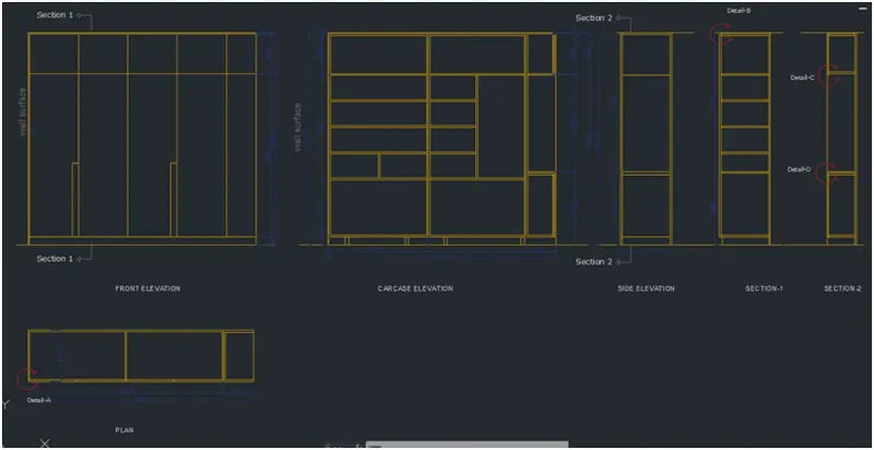
Sketch the cabinet and mention the dimensions and texts
- In command prompt type (startup:1)
- Then file>new
- Then create new drawing window select metric in default settings
- In advanced setup in units check on the decimal, angle in degrees, then ok
- In command prompt type (xl enter h enter v) construction line horizontal and vertical respectively is obtained
- Next, In command prompt type(o and specify distance of offset as 100) and offset the horizontal line to top
- Next, In command prompt type(o and specify distance of offset as 2100) and offset the horizontal line to top
- Next, In command prompt type(o and specify distance of offset as 488) and offset the horizontal line to top
- Next, In command prompt type(o and specify distance of offset as 12) and offset the horizontal line to top
- Next, In command prompt type(o and specify distance of offset as 1223) and offset the vertical line to right
- Next, In command prompt type(o and specify distance of offset as 1200) and offset the vertical line to right
- Next, In command prompt type(o and specify distance of offset as 365) and offset the vertical line to right
- Now select all created objects and in command prompt type tr and then trim all the unwanted lines
- Select all the exterior lines of the cabinet and with copy command move a copy to right.
- Next, In command prompt type(o and specify distance of offset as 100) and offset the horizontal line to top
- Next, In command prompt type(o and specify distance of offset as 12) and offset the horizontal line to top
- Next, In command prompt type(o and specify distance of offset as 680) and offset the horizontal line to top
- Next, In command prompt type(o and specify distance of offset as 12) and offset the horizontal line to top
- Next, In command prompt type(o and specify distance of offset as 300) and offset the horizontal line to top
- Next, In command prompt type(o and specify distance of offset as 12) and offset the horizontal line to top
- Next, In command prompt type(o and specify distance of offset as 300) and offset the horizontal line to top
- Next, In command prompt type(o and specify distance of offset as 12) and offset the horizontal line to top
- Next, In command prompt type(o and specify distance of offset as 300) and offset the horizontal line to top
- Next, In command prompt type(o and specify distance of offset as 12) and offset the horizontal line to top
- Next, In command prompt type(o and specify distance of offset as 488) and offset the horizontal line to top
- Next, In command prompt type(o and specify distance of offset as 12) and offset the horizontal line to top
- Next, In command prompt type(o and specify distance of offset as 300) and offset the horizontal line to top
- Next, In command prompt type(o and specify distance of offset as 1223) and offset the vertical line to right
- Next, In command prompt type(o and specify distance of offset as 1200) and offset the vertical line to right
- Next, In command prompt type(o and specify distance of offset as 365) and offset the vertical line to right
- Now select all created objects and in command prompt type tr and then trim all the unwanted lines
Side elevation
- In command promt l and wake line command and draw line of 630 horizontal and 2600 vertical
- Next, In command prompt type(o and specify distance of offset as 630) and offset the vertical line to right
- Next, In command prompt type(o and specify distance of offset as 100) and offset the horizontal line to top
- Next, In command prompt type(o and specify distance of offset as 12) and offset the horizontal line to top
- Next, In command prompt type(o and specify distance of offset as 800) and offset the horizontal line to top
- Next, In command prompt type(o and specify distance of offset as 12) and offset the horizontal line to top
- Next, In command prompt type(o and specify distance of offset as 1180) and offset the horizontal line to top
- Next, In command prompt type(o and specify distance of offset as 12) and offset the horizontal line to top
- Next, In command prompt type(o and specify distance of offset as 520) and offset the horizontal line to top
- Next, In command prompt type(o and specify distance of offset as 12) and offset the horizontal line to top
- Now select all created objects and in command prompt type tr and then trim all the unwanted lines
Section 1
- Select all the side elevation and paste and offset all the required lines in the middle.
- Similarly to the side elevation create the section 2 with first 365 horizontal line.
- And for the plan, copy all the vertical lines and the bottom horizontal line of the carcase elevation and place them below front elevation
- Next, In command prompt type(o and specify distance of offset as 12) and offset the horizontal line to top
- Next, In command prompt type(o and specify distance of offset as 630) and offset the horizontal line to top
- Next, In command prompt type(o and specify distance of offset as 12) and offset the horizontal line to top
- Trim all the unwanted lines
- Create the all required layer and select everything and add to the cabinet layer with yellow colour
- Select dim laver and type dim in prompt command or select linear dimension in the annotation bar and measure the dimension
- Then type dimcon and do the dimension continuously
- Select all dimension and type DIMSPACE and provide the equal spacing for all the dimensions
- By typing dtext provide the heading for all the drawings and select the layer as the anno
Result:
cabinet with the dimensions and texts were drawn
2
Aim:
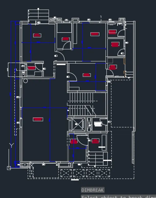
Sketch the dimensions and the missing texts in the floor plan
- In command prompt type (startup:1)
- Then file>new
- Then create new drawing window select metric in default settings
- In advanced setup in units check on the decimal, angle in degrees, then ok
- In command prompt type (xl enter h enter v) construction line horizontal and vertical respectively is obtained
- Go to insert toolbar and select the import pdf option and
- Import the required pdf
- Select the whole imported file and type scale in prompt bar to activate the scale option
- By keeping the exterior wall as the reference calculate the scale factor
- Now select the basepoint
- And enter the scale factor enter
- Now create a layer naming the reference and draw the lines and arc over the layout for the required floor plan with the help of the snapping
- Type qselect and select the layer of the reference and move them separately
- Hence the floor plan is obtained
- Add a layer by name dim in blue colour and with dimcont measure the all required dimensions
- For the interior dimensions of the show with dimlinear and the use the dimension break command for removing the over laying of the dimension linesalso use dimension baseline for the measurement of the dimensions reference to baseline
- Add other layer with the for the annotation of red colour and provide all the namings of the floor plan
- Create the new layer for the dotted line and select all the lines that is to be dotted and assing that layer properties
Result :
Required floor plan is obtained
3
Aim:
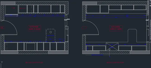
Draw kitchen layout with dimensions and annotation
- In command prompt type (startup:1)
- Then file>new
- Then create new drawing window select metric in default settings
- In advanced setup in units check on the decimal, angle in degrees, then ok
- Go to insert toolbar and select the import pdf option and
- Import the required pdf
- Select the whole imported file and type scale in prompt bar to activate the scale option
- By keeping the exterior wall as the reference calculate the scale factor
- Now select the basepoint
- And enter the scale factor enter
- Now create a layer naming the reference and draw the lines and arc over the layout for the required floor plan with the help of the snapping
- Type qselect and select the layer of the reference and move them separately
- Hence the floor plan is obtained
- Add a layer by name dim in blue colour and with dimcont measure the all required dimensions
- For the interior dimensions of the show with dimlinear and the use the dimension break command for removing the over laying of the dimension linesalso use dimension baseline for the measurement of the dimensions reference to baseline
- Add other layer with the for the annotation of red colour and provide all the namings of the floor plan
- Type ha in the command prompt and wher hatch option is popped
- Select the required hatch and hatch the required area
- Now select the hatched region and change the scale of the hatched portion in the properties toolbar.
Result :
Kitchen layout is drawn
4
AIM:
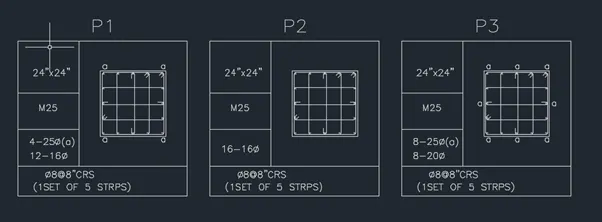
Sketch of the table of the column schedule
- In command prompt type (startup:1)
- Then file>new
- Then create new drawing window select metric in default settings
- In advanced setup in units check on the architectural, angle in degrees, then ok
- In command prompt type (xl enter h enter v) construction line horizontal and vertical respectively is obtained
- Next, in command prompt type(mtext) and write the texts by leaving the spaces for the diagrams and complete all the small sized text that was to written and enter
- Select the craeted horizontal construction line and copy to the desired positions
- Similarlly, Select the craeted vertical construction line and copy to the desired positions
- In command prompt type (tr enter) select all the lines and trim off all the unwanted lines and form the desired shape of the table
- For the heading use DTEXT and type at the required points
- Similarly type dtext and rotate the ‘terrace of unity text’ for 90 degrees
- Draw all the diagrams with help of the line and circle commands and
- Scale the m to required sizes and move them to their respective positions
Result:
Table of the column schedule was obtained
5
Aim:
Draw the detailed raft foundation with column report with dimensions
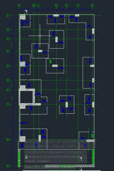
- In command prompt type (startup:1)
- Then file>new
- Then create new drawing window select metric in default settings
- In advanced setup in units check on the architectural, angle in degrees, then ok
- In command prompt type (xl enter h enter v) construction line horizontal and vertical respectively is obtained
- First draw the outline of the raft i.e., boundary
- And draw all the column as the dimentions are measured
- And by keeping these columns as the reference draw all the foundation lines with help of the snapping option
- Trim all the excess lines
- Type xl and place construction line on the origin horizontal an vertical
- And then trim the both lines and select them under the layer of the centre line in line type and in line colour provide green colour.
- Now as per the dimensions provided offset both the horizontal and vertical dotted lines.
- Type ha in the command prompt and wher hatch option is popped
- Select the required hatch and hatch the required area over the column sections
- Now select the hatched region and change the scale of the hatched portion in the properties toolbar.
- Add a layer by name dim in blue colour and with dimcont measure the all required dimensions
- For the interior dimensions of the show with dimlinear and the use the dimension break command for removing the over laying of the dimension lines also use dimension
- Under the layer of the centre line draw the circle and insert the dtext inside the circle
- Select the whole circle and co as endpoint of the circle as the basepoint
- Copy these to and endpoint of the centre line and scale this for the required measurement
- Now copy the scaled circle and attach to all the centreline endpoint
- And then provide the respective naming in the every circle.
Result:
Detailed raft report was drawn.