Creating a Residence Layout, Seating plan, Toilet and Utility room plan using AutoCad
Challenge: -1
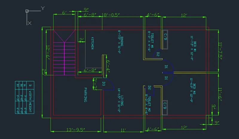
Aim: to sketch a residential plan using AutoCAD software.
Procedure:
- First create a new AutoCAD file with metric settings.
- Set the limits by using LIMITS command specify the left corner point and then the right corner point and enter zoom all the press z enter then a enter.
- Draw the construction lines by command "XL-V" for vertical and "XL-H" for horizontal.
- Now using trim command trim the left side and the top side of the construction line.
- First, we draw the bedroom 1:
- We take an offset of 9" of both the construction lines by using the offset command.
- Then take a offset of 11'7.5" in the horizontal direction and offset of 12' downwards from the horizontal construction line.
- Again, give offset of 4.5" to both lines so that wall thickness is created.
- Trim the extra lines.
- Now we draw the bedroom 2: Now we give an offset of 11'6" from the wall of bedroom 1 in the horizontal direction.
- Offset this wall to 9" on the right side.
- Now using the extend Command: extend the 12' line from bedroom 1 to this line.
- Trim off the rest of the line in horizontal and vertical direction.
- For trim command press TR and double enter.
- Now for Drawing toilet 1:
- Using the offset command: we offset 4'6" downwards and then offset the 4.5" wall
- Now we extend the left side wall towards the line 4'5" and the wall.
- Now from that line offset 8'3" towards +x direction and offset the wall of 4.5"
- Trim off the extra lines using trim command.
- Now for Drawing toilet 2:
- Using extend command: extend the wall thickness of bedroom 2 to 4'6" line.
- Now using offset command: offset a distance of 8'1.5" in -x direction and also 4.5" wall thickness.
- Trim the extra lines using trim command.
- Now we draw dining and living room:
- Now using offset command: give offset of 11' from the wall of toilet and also the wall of 9"
- Now using extend command: extend the left wall towards the 11' and 9" line.
- Now using fillet command: join this line and the wall of toilet 2.
- Now give an offset of 8'7.5" to understand the partition between the dinning and living room.
- Trim off the extra lines of dinning and offset it as 4.5".
- Now we draw the kitchen:
- Using offset command: give an offset from the dinning wall of 6'8" and give an offset of 9" for the wall thickness.
- Extend the wall towards this line.
- Now give an offset of 11" towards + x direction and offset the wall thickness as 9".
- Now we draw parking and staircase room:
- We draw an offset of 12'6" to draw the parking and then give an offset of 9" towards inside.
- Now give an offset of 13'9.5" from the living wall in the downwards direction.
- Extend both the lines towards this line and extend outer wall of kitchen so that the staircase room is defined.
- Now we draw the staircase:
- Size of thread: 1' Size of rise: 6"
- Give a wall thickness of 9" for the staircase room.
- For dividing the staircase give an offset of 3' from the front wall thickness.
- Give offset of 1'(thread) to draw the stairs in plain view.
- Draw 9 offsets as there are 9 risers for 8 steps.
- Trim the lines between handrails and give the other side as dotted line which indicates it is 1st floor stairs which is not visible when viewing ground floor plan view.
- Now we draw the doors:
- Create the opening for respective doors using the width given in the table.
- Draw doors by creating an hinge of 0.5" from the midpoint of both the wall,then drawing a circle with one point on the midpoint of hinge and other at the midpoint of another hinge.
- Now for the windows:
- For living room take an offset of 1'3" as given in the figure.
- Using line command draw a line of 6' from the centre of offseted line inside the wall thickness.
- Trim all the extra line using trim command.
- Now draw kicthen slab and cupboards:
- Offset a distance of 2' to make the kitchen slab.
- Draw the cupboard by creating a rectangle specifying the base point and give dimensions as 5'X2'.
- Copy this rectangle to the other bedroom.
- Now place each component in layers
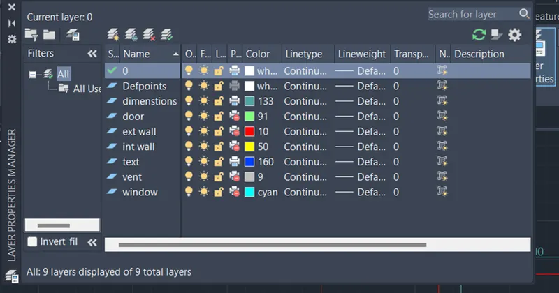
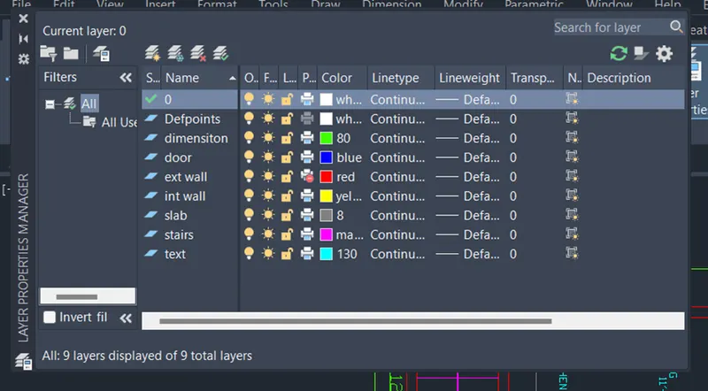
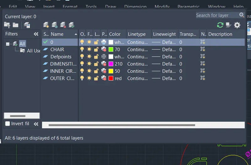
- For layer creation: from layer property create new layer, create 6 layers each for wall, doors, windows, kitchen slab and cupboard, dimensions and stairs.
- Give different colours so that it can distinguished easily.
- Now select the objects and place it in individual layers.
Result: the plan is drawn.
Challenge: 2
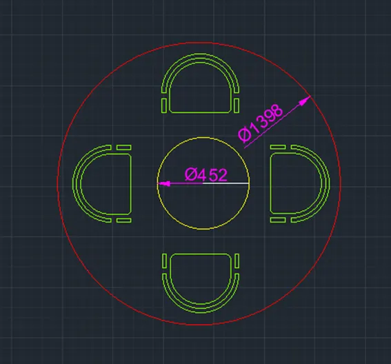
Aim: to sketch the seating plan for an outdoor canopy.
Procedure:
- First create a new AutoCAD file with metric settings.
- Set the limits by using LIMITS command specify the left corner point and then the right corner point and enter zoom all the press z enter then a enter.
- Draw a circle using circle command of radius 1398mm.
- Draw another circle with same centre of radius 452mm.
- Draw an offset of 180mm from inner circle.
- Now draw line along the diameter of bigger circle.
- Now for drawing chairs: Draw a rectangle of length 400mm and width 200mm
- Now draw an arc with start-centre end with the endpoints and centre of the length of the rectangle.
- Now we give two offsets of 50mm using offset command from the arc and join the end points of the offset arc.
- Draw another rectangle of length 70mm and width 50mm using rectangle command.
- Copy this rectangle to another side using rectangle command.
- Now using fillet command fillet the corner of bigger rectangle giving fillet radius 50mm and trim the extra lines.
- Now we move the chair and place it in such a way that it touches the off-setted 180mm circle and the reference diameter line.
- Using move command: select the base point and move to the required place.
- Using mirror command: mirror the chair to the opposite side by selecting base point.
- Now using rotate command: rotate the chair and move it to the left side by selecting the base point
- Again mirroring it to create the chair in the right side.
- Now dimension the circles and trim off extra lines.
Result: the geometry is drawn.
Challenge: 3
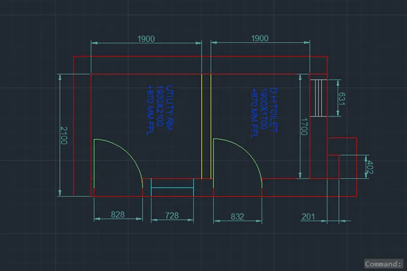
Aim: to sketch the part plan for the toilers and utilities room.
Procedure:
- First create a new AutoCAD file with metric settings.
- Set the limits by using LIMITS command specify the left corner point and then the right corner point and enter zoom all the press z enter then a enter.
- Draw the construction lines by command "XL-V" for vertical and "XL-H" for horizontal.
- Now using trim command trim the left side and the bottom-side of the construction line.
- First we draw the utility room:
- Draw an offset of 300mm from the left side of vertical construction line and an offset of 150mm from the bottom construction line.
- Now draw an offset of 2100mm upwards and offset of 1900mm towards the right side and give the wall thickness as 150mm.
- Now we draw the DH toilet:
- Draw an offset of 1700mm upwards and wall thickness of 300mm using offset command.
- Trim the extra lines using trim command.
- Now we draw the doors: for the utility room take offset distance from the wall and then give an offset of 828mm.
- Trim the extra lines and the opening is created.
- Similarly for the toilet give an offset of 100mm from the wall and then another offset of 832mm.
- Trim the extra lines and the opening is created.
- Now we create the doors: Create a hinge of 25mm and then draw a circle to the midpoint of other side of wall.
- Trim the extra circle to form an arc.
- Now we draw the window of 728mm in the utility room and a ventilator of 631mm in the toilet room.
- Draw the duct behind the toilet by offsetting 201mm and 150mm wall thickness upwards.
- Now extend the wall of toilet towards it and offset 402mm, again offset wall thickness as 150mm.
- Now dimension the lines and trim off extra lines.
Result: the geometry is drawn