Creating a Residence Layout, Seating plan, Toilet and Utility room plan using AutoCad
CREATING A RESIDENCE LAYOUT, SEATING PLAN, TOILET AND UTILITY ROOM PLAN USING AUTOCAD.
1. RESIDENCE PLAN
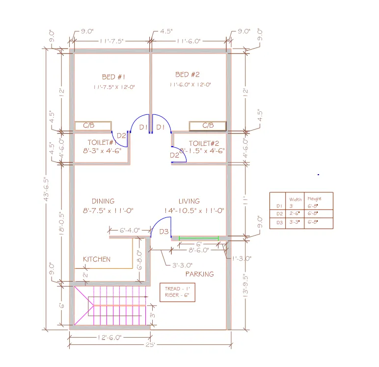
AIM-
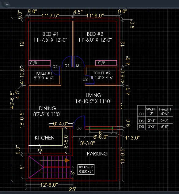
To Draft a layout of Residence Plan as shown in above figure using AutoCAD.
INTRODUCTION -
The residence plan layout is draft using a AutoCAD software using many tools.The plan is drafted with some procedure, so all the step by step procedure is mention below with diagrams and final result is given.
TOOLS USED-
- LINE
- XL LINE
- TRIM
- ARC
- DIMENSION
- OFFSET
- FILLET
- LAYERS
PROCEDUR -
STEP 1
START AUTOCAD
- Go to START MENU, and select AutoCAD.
- The User Interface of AutoCAD is OPEN.
- Click the start Drawing tab
- The workspace of AutoCad is open,
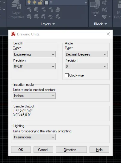
- Enter UNITS in the command box.
- Select ENGINEERING in TYPE, 0'-0.0" in PRECISION, and INCHES in UNITS TO SCALE INSERTED CONTENT.
- Select Angle type as DECIMAL DEGREE, and precision is 0 and direction are Anti-clockwise.
- Press OK.
STEP 2
CREATING LAYERS -
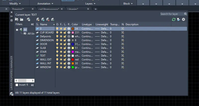
- Click on LAYER PROPERTIES tool or type LA and press ENTER
- A Layer Dialog box will open.
- Click on CREATE NEW LAYER and give a name to layer
- Here, I create a 9 new layer with proper name
- Then, assign a differnt color for differnt layer accourding to our used.
STEP 3
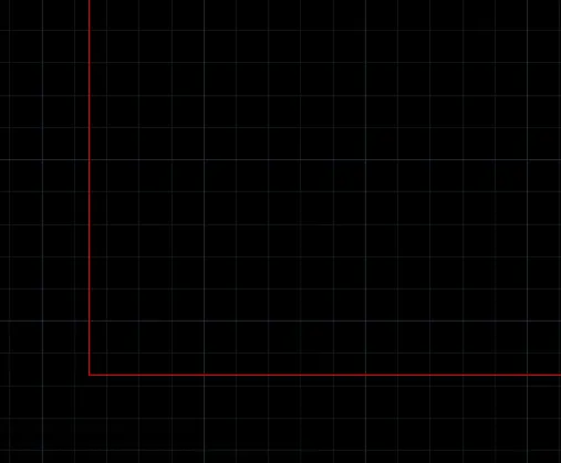
CONSTRUCTION LINE
- Comman for construction line is XL and press ENTER
- Type XL ENTER and V ENTER for vertical line
- Type XL ENTER and H ENTER for horizontal line
- Select a TRIM tool or type TR and press ENTER.
- TRIM the unwanted line
STEP 4
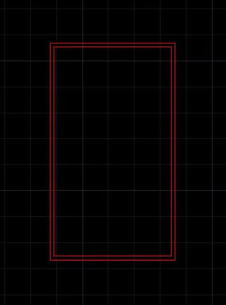
CREATING OUTER LAYOUT
- Select a OFFSET tool or type O and ENTER.
- Select a Through in the command line
- Now, select a vertical line and give offset as 9" in right side.
- Select same line and give of offset as 25' on the right side
- Now select a last line and give an offset on the inner side of 9".
- Press ESC
- Select a OFFSET tool or type O and ENTER.
- Select a Through in the command line
- Now, select a horizontal line and give offset as 9" on the upper side.
- Select same line and give of offset as 43'6.5" in the upper side
- Now select a last line and give an offset on the lower side of 9".
- Press ESC
- Select a TRIM tool or type TR and press ENTER.
- TRIM the unwanted line
STEP 5
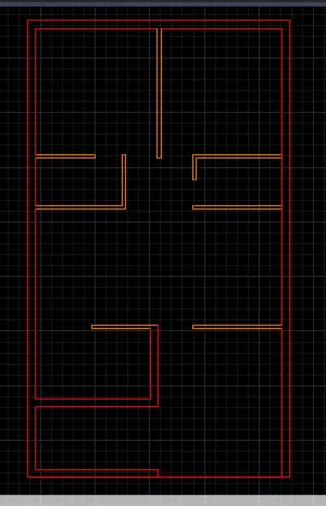
CREATING INNER WALLS
- Select the INNER WALL LAYER
- Select a OFFSET tool or type O and ENTER.
- Select a Through in the command line
- Now, select a vertical line and give offset as 11'-75" in right side.
- Select offset line and give of offset as 4.5" on the right side
- Press ESC
- Select a OFFSET tool or type O and ENTER.
- Select a Through in the command line
- Now, select a top horizontal line and give offset as 12' on the lower side.
- Select new line and give of offset as 4.5" in the l0wer side
- Now select a last line and give an offset on the lower side of 4'-6".
- Select new line and give of offset as 4.5" in the l0wer side
- Press ESC
- Select a TRIM tool or type TR and press ENTER.
- TRIM the unwanted line
- Now we get two toilet and two bedroom
- Select a OFFSET tool or type O and ENTER.
- Select a Through in the command line
- Now, select a vertical line and give offset as 12'-6.0" in right side.
- Select offset line and give of offset as 9" on the left side
- Press ESC
- Select a OFFSET tool or type O and ENTER.
- Select a Through in the command line
- Now, select a horizontal line and give offset as 6' on the upper side.
- Select same line and give of offset as 9" in the upper side
- Select a last line and give an offset on the upper side of 6'8.0".
- Now select a last line and give an offset on the upper side of 4.5".
- Press ESC
- Select a TRIM tool or type TR and press ENTER.
- TRIM the unwanted line
STEP 6
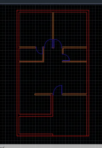
CRETATING DOOR
- Select the DOORS LAYER
- Door D3 is created at the entrance with a width of 3'3".
- Door D1 is created at the entry of each BEDROOM with a width of 3'.
- Door D2 is created at the entry of each TOILET with a width of 2'6".
- Select a line tool or type L and press ENTER.
- Create a hinge of 2' by 3'
- Now create a Line as a width of door
- Select a ARC tool from the ribbion and select a Start,End,Direction and create a arc which a swing of Door.
STEP 7
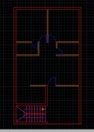
CREATING STAIRCASE
- Select the STAIR LAYER
- Select a OFFSET tool or type O and ENTER.
- Select a Through in the command line
- Now, select a HORZONTAL bottom line and give offset as 3' on the upper side.
- Press ESC
- slect a line tool or type L and press ENTER.
- DRAW a 6' line and give offset of 1'
- Create a 8 step of stair
- And , give the direction for flight.
STEP 8
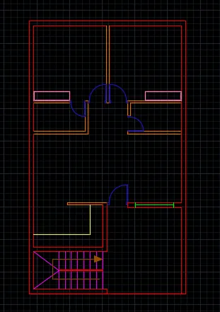
CREATING CUPBOARD AND KITCHEN SLAB
- Select a CUBBOARD LAYER
- Select a RECTANGLE tool or type REC and press ENTER
- Click on DIMENSION
- Specify a length of rectangle as a length of wall.
- and specify the width of rectangle as 1'6"
- Select the OFFSET tool and give some offset in inner side of rectangle
- Select a COPY tool or type CO and press ENTER.
- Select a RECTANGLE and copy on another side.
- Select a SLAB LAYER
- Select OFFSET tool or type a O and press ENTER
- Specify offset distance as 2'
- Now TRIM the LINES.
STEP 9
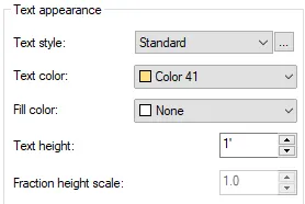
- Open a dimension-style dialog box by pressing DIMSTY in the command line.
- Click on the Modify tab.
- Now go to the text and change the text heightand color as per Requirement.
- Here, I used a 1' unit for a text height
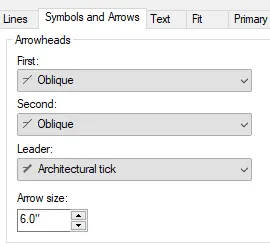
- Open a dimension-style dialog box by pressing DIMSTY in the command line.
- Click on the Modify tab.
- Now go to the text and change the arrow size and color as per Requirement.
- Here, I used a 6" unit for a text height
- Give the all dimension for the drawing as shown in fig.
- For liner dimension, Enter DIMLIN
- For angular dimension,Enter DIMANG
- And for diameter, Enter DIMDIA
RESULT -
2.SEATING PLAN FOR OUTDOOR CANOPY
AIM-
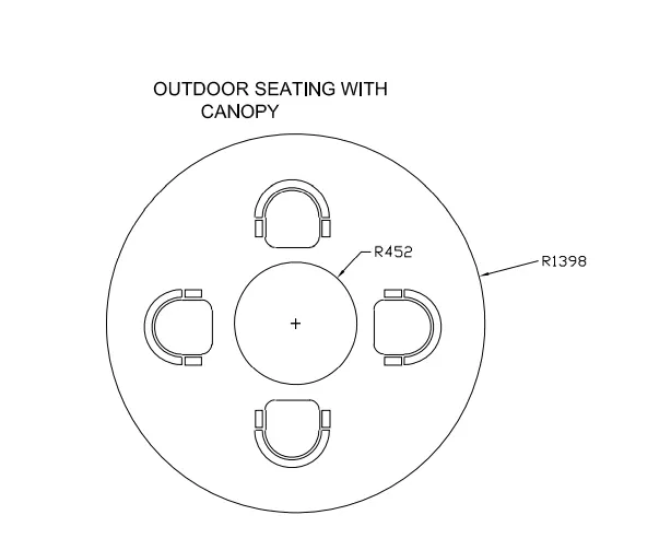
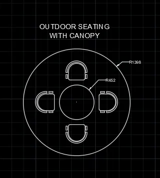
To Draft a layout of seating plan for outdoor canopy as shown in above figure using AutoCAD.
INTRODUCTION -
The layout of seating for outerdoor conopy is draft using a AutoCAD software using many tools.The plan is drafted with some procedure, so all the step by step procedure is mention below with diagrams and final result is given.
TOOLS USED-
- LINE
- XL LINE
- TRIM
- ARC
- DIMENSION
- OFFSET
- FILLET
- LAYERS
PROCEDUR -
STEP 1
- Go to START MENU, and select AutoCAD.
- The User Interface of AutoCAD is OPEN.
- Click the start Drawing tab
- The workspace of AutoCad is open,
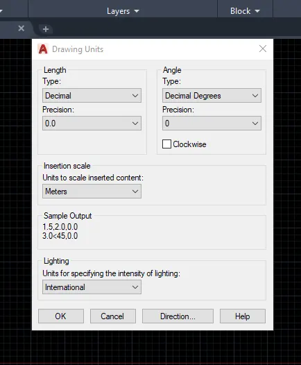
- Enter UNITS in the command box.
- Select DECIMAL in TYPE, 0.0 in PRECISION, and METERS in UNITS TO SCALE INSERTED CONTENT.
- Select Angle type as DECIMAL DEGREE, and precision is 0 and direction are Anti-clockwise.
- Press OK.
STEP 2
- Click on the Circle tool or type C and press ENTER.
- Select the Centre, Radius
- Specify the centre point of circle
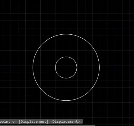
- Specify Radius of circle as 452.
- Again, click on the Circle tool or type C and press ENTER.
- Select the Centre, Radius
- Specify the centre point of circle as the same point of last circle
- Specify Radius of circle as 1398.
STEP 3
- select the Rectangle tool by entering RECTANG
- Specify the first point of the rectangle.
- Select Dimensions option in the command line.
- Specify length of rectangle
- Specify width of rectangle
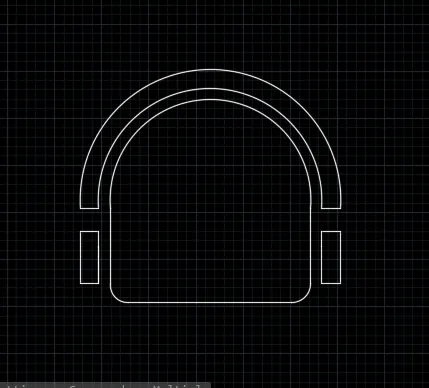
- Select the Fillet tool, by entering 'F' in the command tab.
- Selct the Radius option in the command line, and specify a radius
- Then select the lines to fillet the bottom two corners of the rectangle.
- Click on the CIRCLE tool in the ribbon and select the 2 POINT option from the drop down list.
- Create a cicle and then trim a semicircle
- Select the Offset tool by entering ‘OFFSET’ command in the command tab.
- Specify an offset distance
- Select the semi circle created earlier, and then click on the outside of the circle
- Press Esc to cancel the OFFSET command.
- Select the Line tool and draw lines to close the ends of the arcs.
- To draw the chair arms, select the Rectangle tool and draw rectangles of length and width
STEP 4
- Select a COPY tool or type CO and press ENTER
- Select a Chair and press ENTER
- Specify base point as Center of semi circle and place on between these two circle.
- Now select a SCALE tool and scale the chair according to drawing

STEP 5
- Select a chair and,
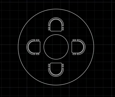
- Click on POLAR ARRAY
- Select a center of array is the center of circle
- Select a no of ITEMS as 4
- press ESC.
STEP 6
- Open a dimension-style dialog box by pressing DIMSTY in the command line.
- Click on the Modify tab.
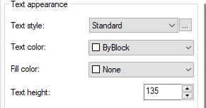
- Now go to the text and change the text heightand color as per Requirement.
- Here, I used a 135 unit for a text height
- Open a dimension-style dialog box by pressing DIMSTY in the command line.
- Click on the Modify tab.
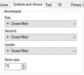
- Now go to the text and change the arrow size and color as per Requirement.
- Here, I used a 75 unit for a text height
- Give the all dimension for the drawing as shown in fig.
- For liner dimension, Enter DIMLIN
- For angular dimension,Enter DIMANG
- And for diameter, Enter DIMDIA
RESULT -
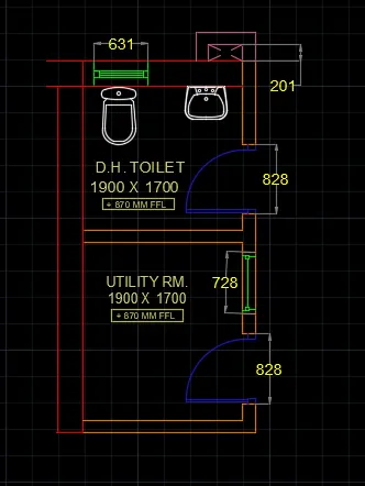
3. TOILERS AND UTILITIES ROOM
AIM-
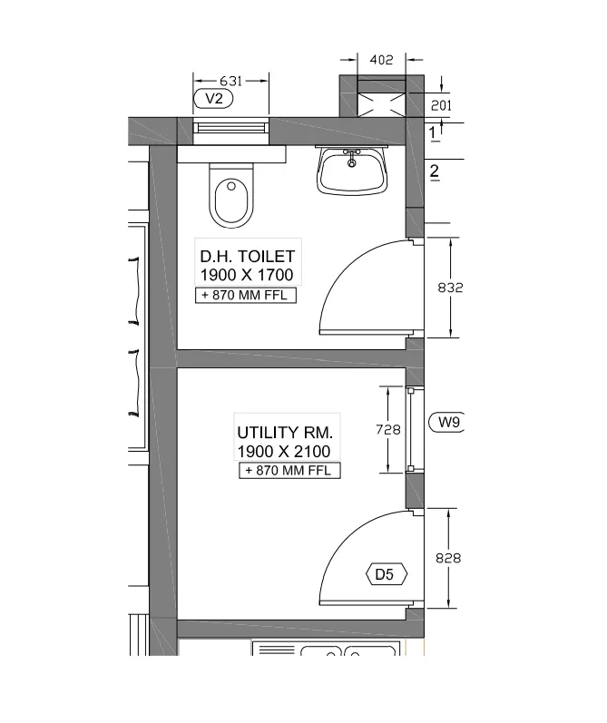
To Draft a layout of Residence Plan as shown in above figure using AutoCAD.
INTRODUCTION -
The residence plan layout is draft using a AutoCAD software using many tools.The plan is drafted with some procedure, so all the step by step procedure is mention below with diagrams and final result is given.
TOOLS USED-
- LINE
- XL LINE
- TRIM
- ARC
- DIMENSION
- OFFSET
- FILLET
- LAYERS
PROCEDUR -
STEP 1
START AUTOCAD
- Go to START MENU, and select AutoCAD.
- The User Interface of AutoCAD is OPEN.
- Click the start Drawing tab
- The workspace of AutoCad is open,
- Enter UNITS in the command box.
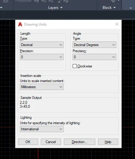
- Select DECIMAL in TYPE, 0 in PRECISION, and METERS in UNITS TO SCALE INSERTED CONTENT.
- Select Angle type as DECIMAL DEGREE, and precision is 0 and direction are Anti-clockwise.
- Press OK.
STEP 2
CREATING LAYERS
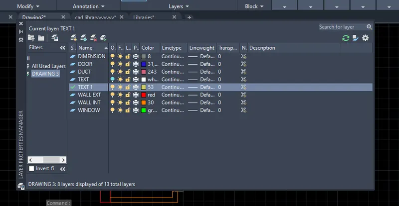
- Click on LAYER PROPERTIES tool or type LA and press ENTER
- A Layer Dialog box will open.
- Click on CREATE NEW LAYER and give a name to layer
- Here, I create a 7 new layer with proper name
- Then, assign a differnt color for differnt layer accourding to our used.
STEP3
CONSTRUCTION LINE
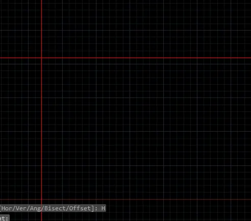
- Comman for construction line is XL and press ENTER
- Type XL ENTER and V ENTER for vertical line
- Type XL ENTER and H ENTER for horizontal line
- Select a TRIM tool or type TR and press ENTER.
- TRIM the unwanted line
STEP 4
CREATING OUTER WALLS
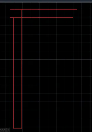
- Select a OFFSET tool or Type a O and press ENTER
- Specify a offset distance a 300 and
- Select Both the line one by one
STEP 5
CREATING INNER WALLS
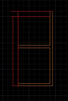
- Select a OFFSET tool or Type a O and press ENTER
- Specify a offset distance a 1900 and
- Select the VERTICAL line AND CLICK
- Select a OFFSET tool or Type a O and press ENTER
- Specify a offset distance a 150 and
- Select the line AND CLICK
- Press ESC
- Select a OFFSET tool or Type a O and press ENTER
- Specify a offset distance a 170 and
- Select the HORIZONTAL line AND CLICK
- Select a OFFSET tool or Type a O and press ENTER
- Specify a offset distance a 150 and
- Select the horizontal line AND CLICK
- Press ESC
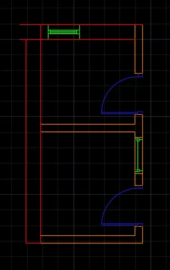
STEP 6
CREATING DOORS
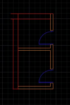
- Select the DOORS LAYER
- Door D5 is created with a width of 828.
- Create a hinge of 2' by 3'
- Now create a Line as a width of door
- Select a ARC tool from the ribbion and select a Start,End,Direction and create a arc which a swing of Door.
STEP 7
CREATING VENTILATOR AND WINDOW
- Select the WINDOWS LAYER
- Select a OFFSET tool or Type a O and press ENTER
- Specify a offset distance as 145 then 631 as a width of ventilator
- Select a OFFSET tool or Type a O and press ENTER
- Specify a offset distance as 112 then 728 as a width of window.
STEP 8
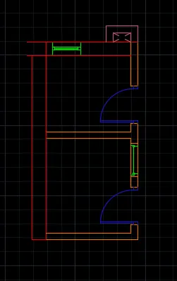
CREATING DUCT
- To draw the duct, select the Duct layer as the default layer in the Layer panel.
- Select the Rectangle tool or type REC and press ENTER
- Specify the first point as the top right outer corner of the Toilet.
- Select Dimensions option in the command line.
- Specify length of rectangle as 402
- Specify width of rectangle as 401
- Select the Offset tool or type O and press ENTER
- Specify an offset distance of 150.
- Select the rectangle drawn earlier.
- Specify the point on side to offset.
- Press Esc to cancel the Offset command.
STEP 9
- Open a dimension-style dialog box by pressing DIMSTY in the command line.
- Click on the Modify tab.
- Now go to the text and change the text heightand color as per Requirement.
- Here, I used a 135 unit for a text height
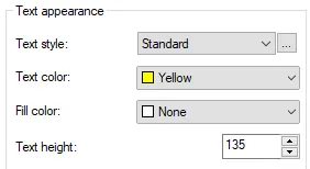
- Open a dimension-style dialog box by pressing DIMSTY in the command line.
- Click on the Modify tab.
- Now go to the text and change the arrow size and color as per Requirement.
- Here, I used a 75 unit for a text height
- Give the all dimension for the drawing as shown in fig.
- For liner dimension, Enter DIMLIN
- For angular dimension,Enter DIMANG
- And for diameter, Enter DIMDIA
RESULT -