Creating a Residence Layout, Seating plan, Toilet and Utility room plan using AutoCad
1. Residence Plan:
Sketch the layout of a residence as shown in the figure 1. Consider all the dimensions as reference to sketch the unit plan. Also the text in the layout are only for reference. Assume the missing dimensions. Also, refer the schedule for size of the doors.
AIM:
To draw the given residential plan with the details given.
INTRODUCTION:
- Residential layout is ideal for students and practitioners of urban design, planning, enginnering, architecture and landscape seeking a comprehensive guide to the theory and practice of designing and laying out residential areas.
- Commands used:
- Limmax command
- Limits command
- Zoom command
- Xline command
- Line command
- Dimlinear command
- Dimstyle command
- Units command
- Text command
- LW command
- Extend command
- Trim command.
PROCEDURE:
- First create a new AutoCAD file with imperial settings.
- Make sure that in units the type is "Engineering" (as the dimension is in feet and inches) and also set the precision.
- Set the limits with command "LIMITS" specify the left corner points and right corner points and Enter zoom all.
- Draw construction lines by command XL-V for vertical and XL-H for horizontal.
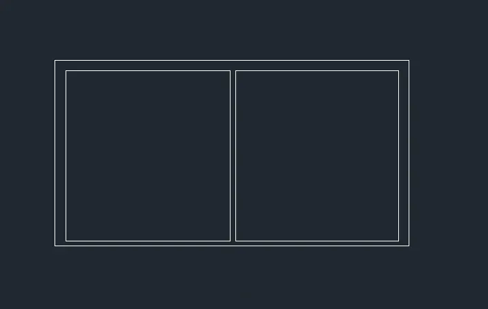
Drawing bed 1:
- Take offset of both construction lines of 9" by using command O give offset distance as 9" in the command box.
- Then take the offset of 11'-7.5" to the positive X-direction and offset of 12' in negative Y-direction so that the room is formed.
- Again, give offset to the both lines with 4.5" so that the wall thickness is created.
- Trim off the unwanted lines.
Drawing bed 2:
- Give offset from the wall thickness of bed 1 towards positive X-direction of 11'-6".
- Offset the 9" to create wall on right side.
- Extend the line of 12' from bed 1 towards this line. Command EX select the line to where it should be extended 4.5" offset line of bed 2.
- Trim off the rest of the lines.
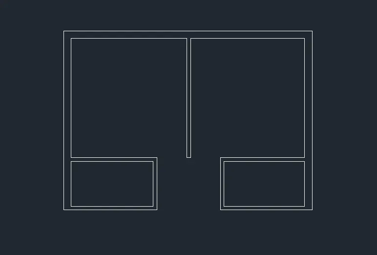
Drawing Toilet 1:
- Offset 4'-6" downward then also offset 4.5" wall.
- Extend the left side wall towards the line 4'-6" and the wall.
- From that line offset 8'-3" towards positive X-direction and offset the wall of 4'-5" also.
- Trim off the unwanted lines.
Drawing Toilet 2:
- Extend the wall thickness of bed 2 to the 4'-6" line.
- Offset a distance of 8'-1.5" towards positive X-direction and also 4'-5" wall thickness.
- Trim off the unwanted lines.
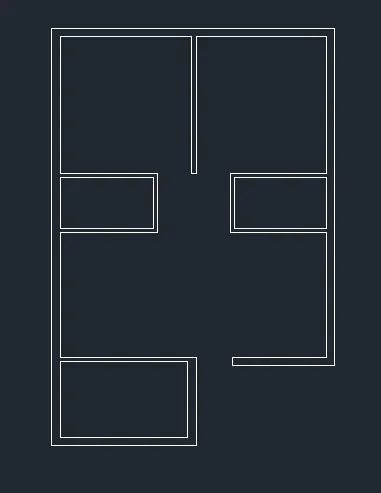
Drawing dining and living room:
- Give offset of 11' from the wall of toilet and also the wall of 9".
- Extend the left wall towards the 11' line and 9" line.
- Use fillet to join this line and the wall of toilet 2.
- Give an offset of 8'-7.5" to understand the partition between the dining and living.
- Trim off the wall thickness of dining and offset it as 4.5".
Drawing Kitchen:
- Give an offset from the dining wall of 6'-8" and give an offset of 9" for the wall thickness.
- Extend the left wall towards this line.
- Give an offset of 11" towards positive X-direction and offset the wall thickness as 9".
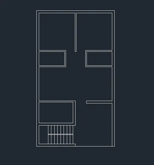
Drawing, Parking and Staircase:
- Draw offset of 12'-6" to draw the parking, then give offset of 9" towards inside.
- Give offset 13'-9.5" from the living wall towards downwards.
- Extend both side lines towards this line.
- Extend outer wall of kitchen, so that the staircase room is defined.
Drawing Staircase:
- Given: Thread = 1", Riser = 6"
- Give a wall thickness of 9" for the staircase room.
- Divide the staircase by giving offset of 3' from the front wall thickness.
- Give an offset of 1.96" to show the handrail (Assume 5 cm is usually given).
- Draw offset of 1' (thread) to draw the stairs in plain view.
- Draw nine offsets as there are nine risers for 8 steps.
- Trim of the lines between the handrails and give the other side as dotted lines (it indicates that it is the upward stairs, not visible when viewing ground floor plan).
- For that select the lines and change the line type to ISO dash.
- Mark the direction of stairs.
Drawing Doors:
- Trim all the door opening with their respective width D1=3', D2=2'-6", D3=3'-3'.
- For open kitchen, trim the line retaining a distance of 6'-4" from right side of kitchen.
- Draw doors creating a hinge of 0.5" from the midpoint of both the wall, then drawing a circle with one point on the midpoint of one hinge and other the midpoint of another hinge.
Place the Windows:
- For living, take an offset of 1'-3", this is where the window starts (as it is given).
- Using line command draw a line of 6' from the centre of offset line inside the wall thickness.
- Trim all the unwanted lines and fillet the corners with fillet radius zero.
- Command fillet "F" select both the lines.
Drawing the kitchen slab and cupboards:
- Offset a distance of 2' to make the kitchen slab.
- Draw the cupboard by creating a rectangle Command "REC"- specify base point- click on dimension- give dimension as 5'`times`2'.
- Copy the rectangle to another bedroom also.
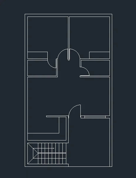
Placing each component in layer:
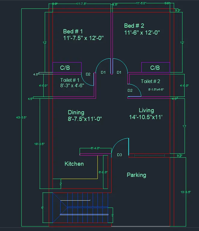
- From layer property- create new layer- create 8 layers each for wall, door, window, stairs, kitchen slab and cupboard.
- Nae each layer as well, door, window, stairs, kitchen slab, dimensions, text and cupboard and give different colours, so that it can be identified separately.
- Select the objects and place it in respective layers.
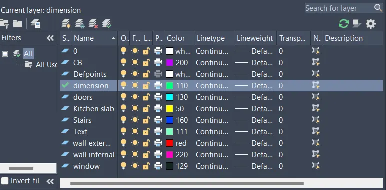
RESULT:
The layout of a residence plan is drawn.
2. Sketch the seating plan for an outdoor canopy. Assume the dimensions for seating. Also consider the dimension in mm.
AIM:
To draw the seating plan for an outdoor canopy.
Command used:
- Circle
- Offset
- Fillet
- Extend
- Trim.
PROCEDURE:
Creating circles:
- Select metric units as the dimensions is in mm
- Draw a circle with a command "C" select a centre point and give the radius as 1398 mm.
- Draw another circle with same centre with radius 452 mm.

- Next here we have to draw the rectangle inside the first circle, then we have to enter the fillet command and select the rectangle corner to fillet it.
- Next we select the arc command to create are left side of the rectangle.

- Copy the created chair and use array command.
- By using polar array and providing the number of items as 4 the chairs are created as shown below.
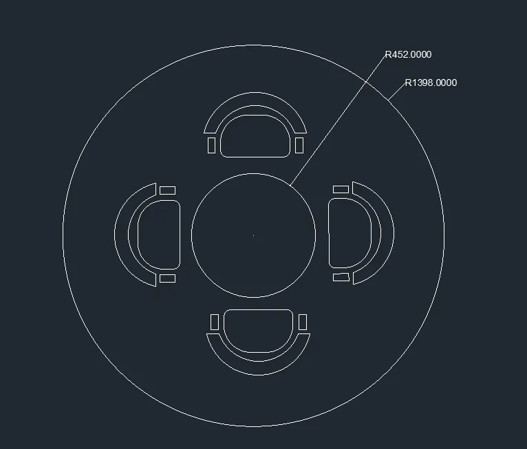
RESULT:
An outdoor canopy is created as per the details given using AutoCAD.
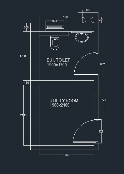
3. Sketch the part plan for the toilet and utilities room. Consider the outer wall thickness as 300 mm and inner wall thickness 150 mm. Also, assume the missing dimension, texts, dimensions and hatches are only for references. Also, symbols for toilets and w/c are also for references.
AIM:
To draw the part plan for the toilets and utilities in detail.
INTRODUCTION:
- A toilet room usually consists of obviously a toilet, lavatory and all the accessones, such as grab bars and dispensers.
- There are many layouts of this type but we will explore one very simple design and the code requirements for each.
- The utility room has several uses but typically functions as an area to do laundry.
- This room contains laundry equipment such as a washing machine, tumble dryer ironing board and clothes iron.
- The room is also used for closet organization and storage.
- The room would normally contain a second coat closet which is used to store seasonal clothing such as winter costs or clothing which are no longer used daily.
COMMAND USED:
- Limmax command
- Limits command
- Zoom command
- Line command
- Dimlinear command.
PROCEDURE:
- First create a new AutoCAD file with metric units.
- Set the limits with command "LIMITS".
- Specify the left corner points and right corner points and enter zoom all.
- Draw construction lines by command XL-V for vertical and XL-H for horizontal.
- Trim the left side and bottom position of the construction lines.
Drawing Utility room:
- Draw an offset of 300 mm from the left side of vertical construction line and an offset of 150 mm from the bottom horizontal line.
- Draw an offset of 2100 mm upwards and offset of 1900 mm towards the right side and give the wall thickness of 150 mm and 300 mm respectively.
Drawing DH Toilet:
- Draw an offset of 1700 mm upwards and wall thickness 300 mm as it is the external wall and a room is formed.
- Trim off the rest of the construction lines.
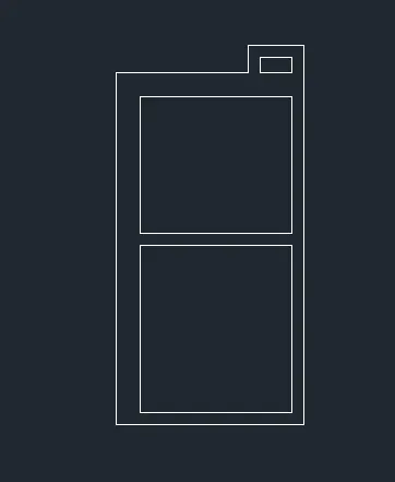
Create opening of doors:
- From toilet, after offset of 100 mm, give another offset of 832 mm and trim to form the door opening by creating 12.5 mm hinge and then draw circle to the midpoint of other side of wall. Trim off the rest of circle to form an arc.
- Draw window of 728 mm in the utility room and a ventilator of 631 mm in toilet room.
- Draw the duct shown behind the toilet room by offset at a distance of 201 mm and 150 mm wall thickness upwards.
- Extend the wall of toilet towards it and offset 402 mm, offset wall thickness as 150 mm.
- Fillet the corners of the room.
Drawing of utility symbols:
- In the command line enter DS and select en-us-home utility-select the symbols by draging them into AutoCAD screen and place where ever required.
RESULT:
The plan for the toilers and utilities room is drawn.