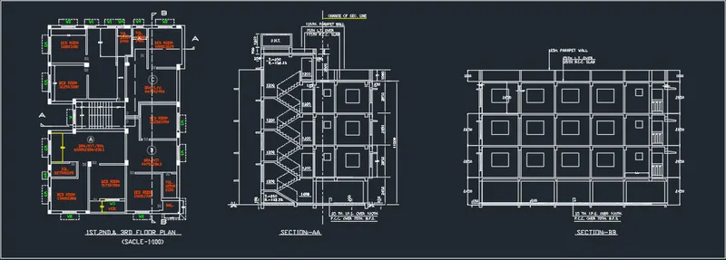
Creating a Layout, Section and Elevation with dimensions using AutoCad
1. Create the Plan and Sections as shown in the Figures. Use proper dimension techniques and dimension styles to document the project. Assume the sizes of the doors and windows as per construction standards. Refer to sections for stair details if required.
1.Aim:
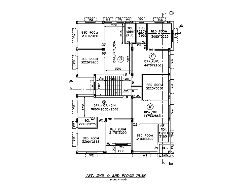
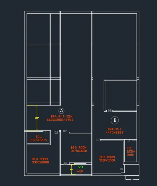
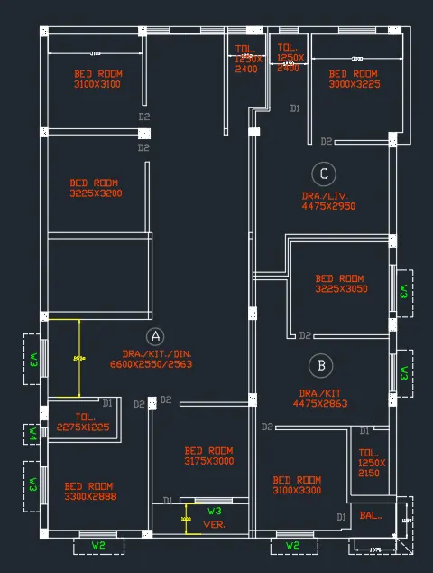
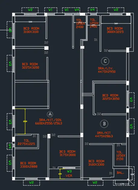
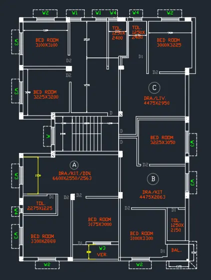
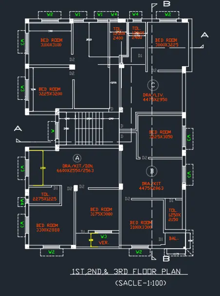
To Create a Floor Plan 1,2&3 by using Auto Cad.
INtroduction:
- To Create a Floor Plan 1,2&3 by using a various command.
- Now we see the Step by Step Producre to Create a Drawing.
Floor Plan 1,2&3:
- we create a Floor Plan 1,2&3 elevation,plan, and with section.
- First we need study the plan properly before start the plan.
- And we need Draw the plan as per dimension.
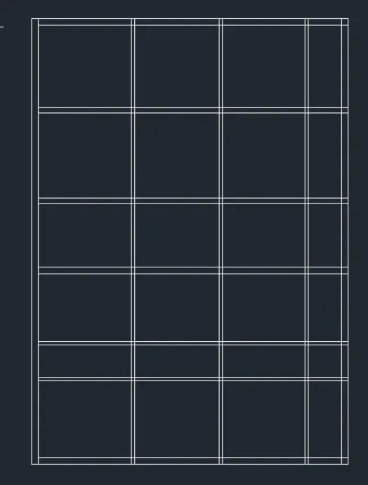
- Click 'REC' Rectangle command to draw the outer of the plan.
- And offset the 250mm of outer wall and inner wall 125mm.
- After Click 'L'Line command to draw the center line.
- And click 'OF'Offset commend to offset the Line.
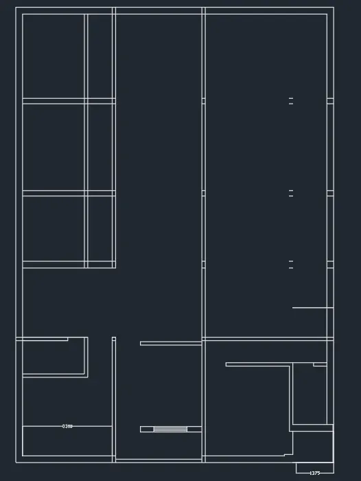
- Create a rooms as per dimensions using of ofset command.
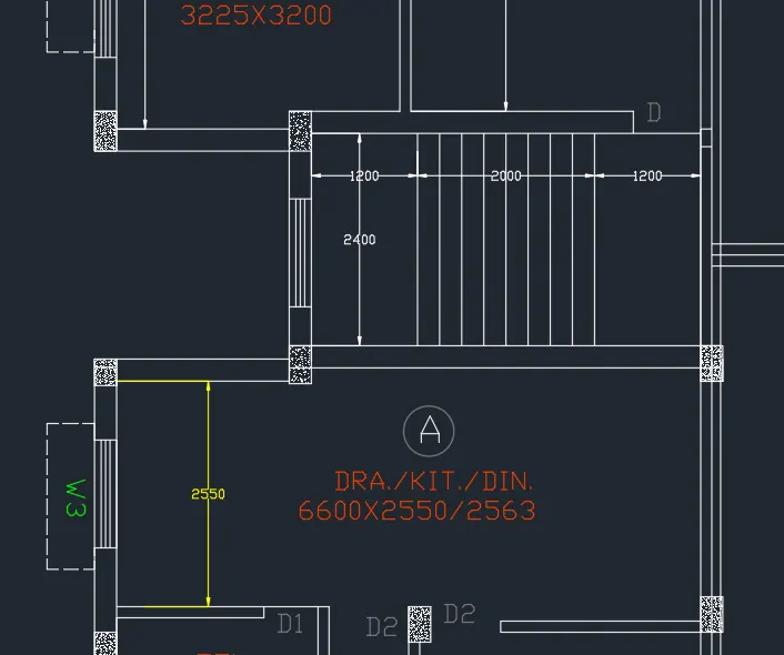
- And create a Staircase as per dimension with a 250mmouter wall.
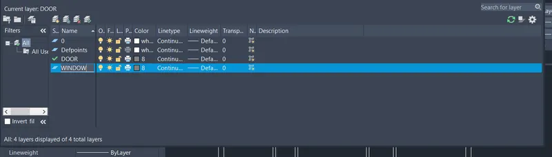
- Then we create a 'Layer Properties'with a different layer.
- Create a Layer for window,door,and dimension.
- Windows and door are create with standart size using in residencial building
- And cut the SectionAA and SectionBB in different side.
- Also insert text with help of Dtext command or Single Line text.
- Click "DTEXT" command to create the text.
- Thyen create the Room name given in plan.
- Click 'DIM'to create a dimension of the plan.
- And check the dimesnion before save.
- And Click "SAVE"command to save the Text.
- Finally we SNIPPING TOOL to screenshot the drawing.
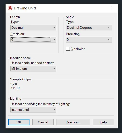

2.Aim:
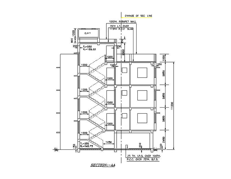
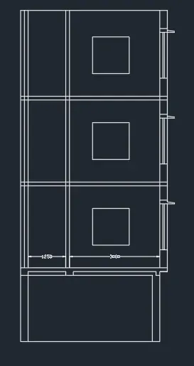
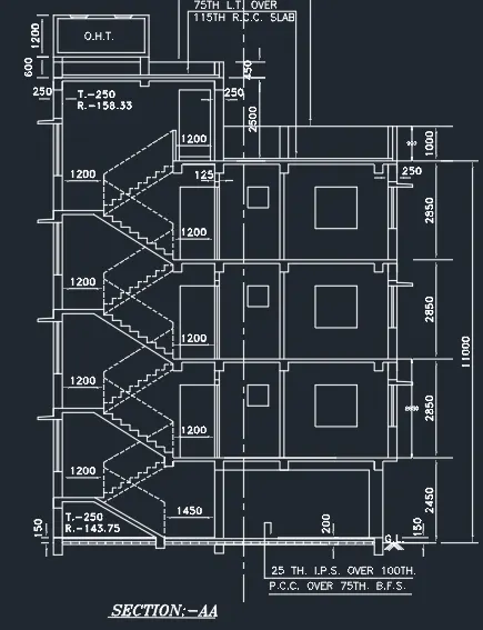
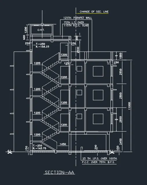
To Create a SectionAA by using Auto Cad.
INtroduction:
- To Create a SectionAA by using a various command.
- Now we see the Step by Step Producre to Create a Drawing.
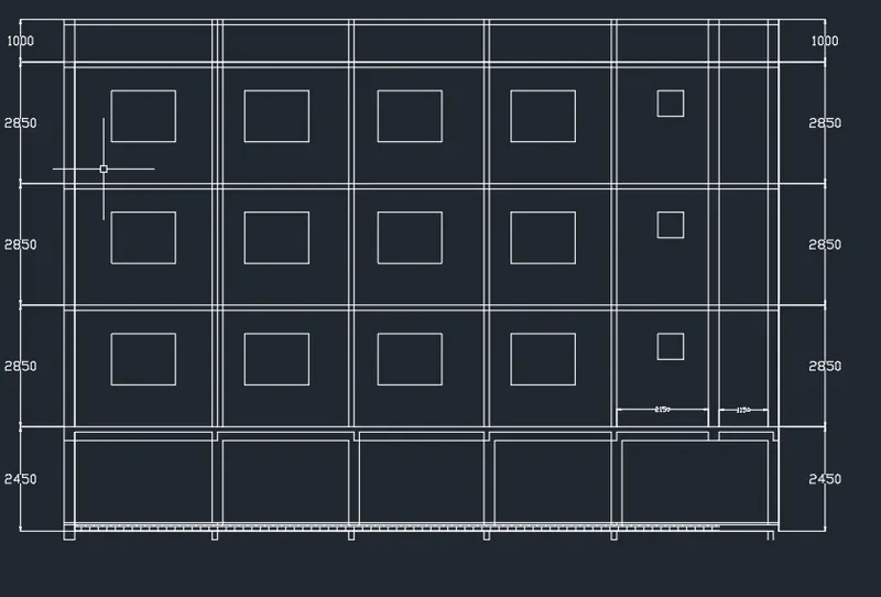
SectionAA:
- we create a SectionAA .
- First we need study the where we cut the sectionAA properly before start the plan.
- And we need Draw the plan as per dimension.
- Click 'REC' Rectangle command to draw the outer of the plan.
- And offset the 250mm of outer wall and inner wall 125mm.
- After Click 'L'Line command to draw the center line.
- And click 'OF'Offset commend to offset the Line.
- Create a rooms as per dimensions using of ofset command.
- And create a Staircase as per dimension with a 250mmouter wall.
- Windows and door are create with standart size using in residencial building
- Also insert text with help of Dtext command or Single Line text.
- Click "DTEXT" command to create the text.
- Click 'DIM'to create a dimension of the plan.
- And check the dimesnion before save.
- And Click "SAVE"command to save the Text.
- Finally we SNIPPING TOOL to screenshot the drawing.
3.Aim:
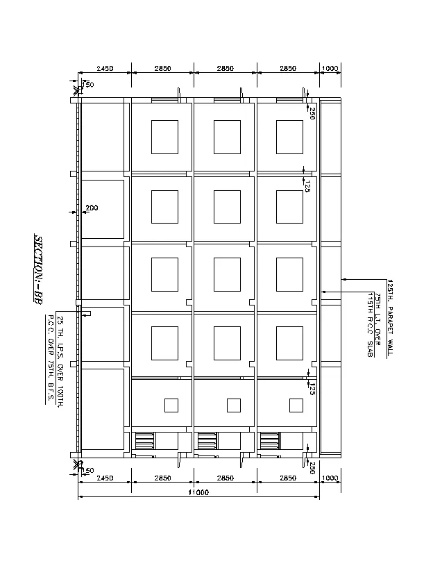
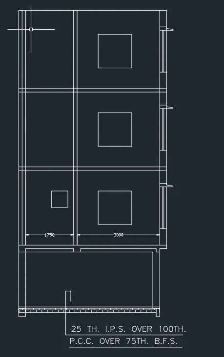
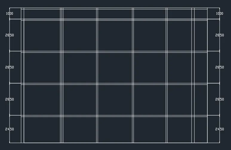
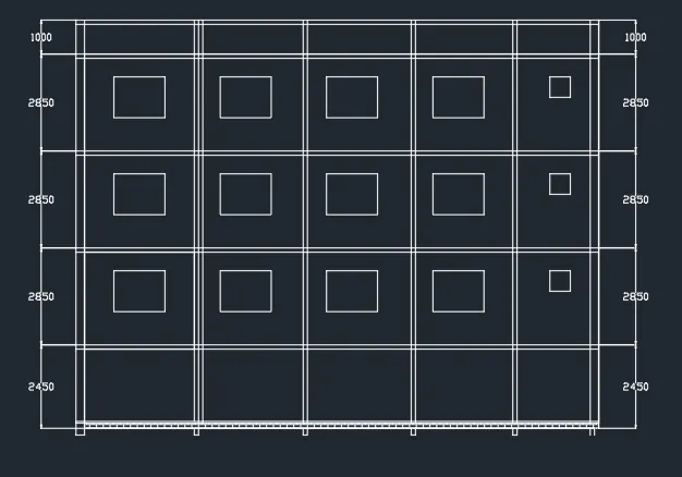
To Create a SectionBB by using Auto Cad.
INtroduction:
- To Create a SectionBB by using a various command.
- Now we see the Step by Step Producre to Create a Drawing.
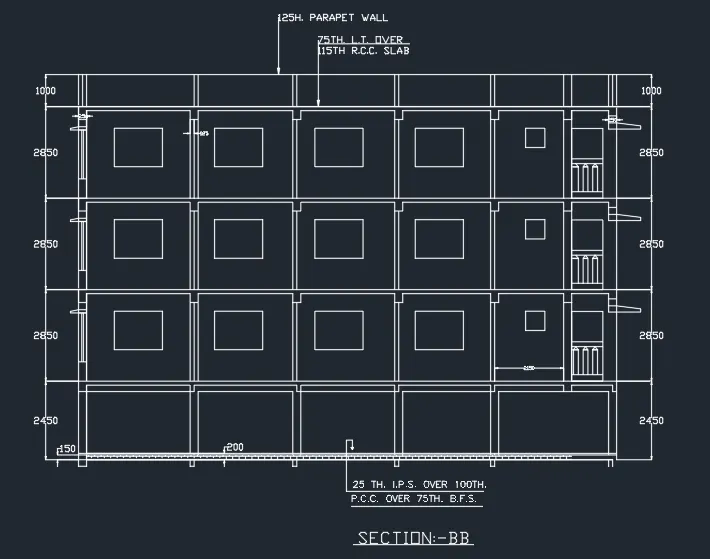
SectionBB:
- we create a SectionBB .
- First we need study the where we cut the sectionBB properly before start the plan.
- And we need Draw the section as per dimension.
- Click 'REC' Rectangle command to draw the outer of the plan.
- And offset the 250mm of outer wall and inner wall 125mm.
- After Click 'L'Line command to draw the center line.
- And click 'OF'Offset commend to offset the Line.
- Create a rooms as per dimensions using of ofset command.
- Windows and door are create with standart size using in residencial building
- Also insert text with help of Dtext command or Single Line text.
- Click "DTEXT" command to create the text.
- Click 'DIM'to create a dimension of the plan.
- And check the dimesnion before save.
- And Click "SAVE"command to save the Text.
- Finally we SNIPPING TOOL to screenshot the drawing.

RESULT:
Finally we learn about Plan of residensical building with sectionAA and BB.