Creating a Layout, Section and Elevation with dimensions using AutoCad
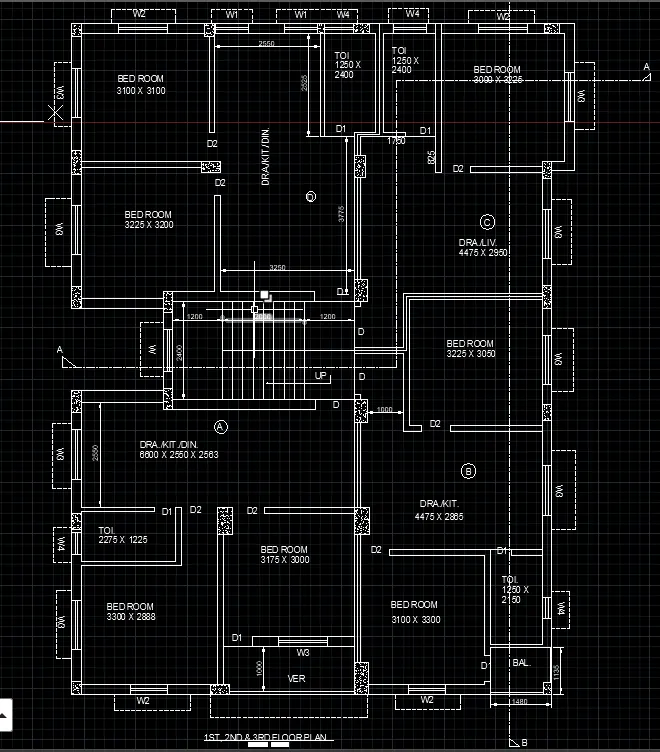
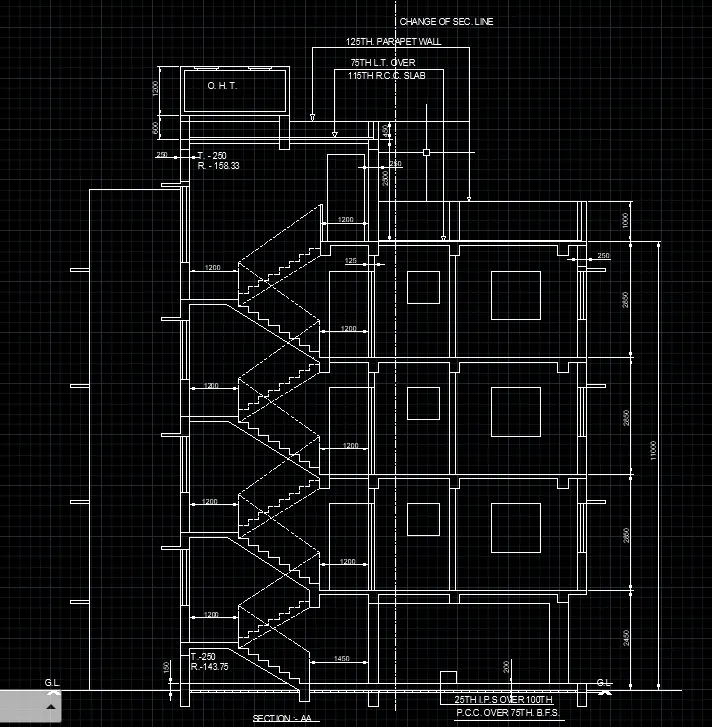
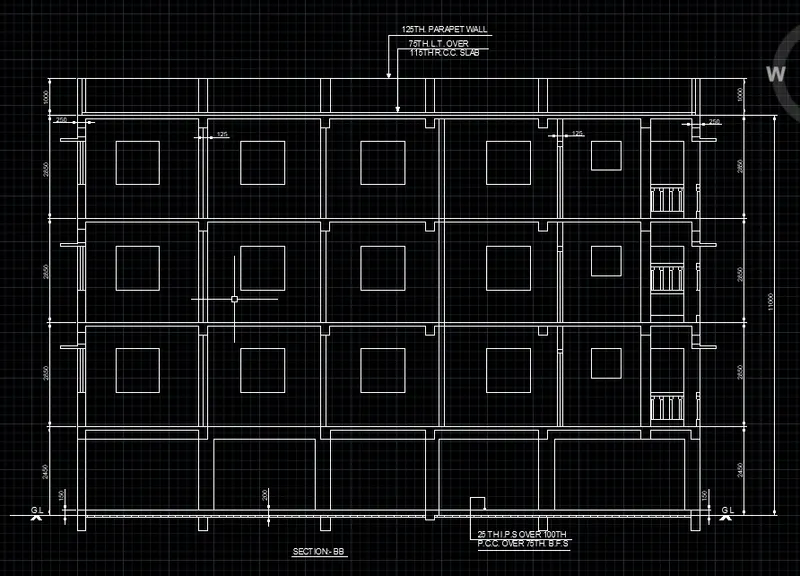
Aim: To create a plan sections as shown in fig.
Procedure:
- In command prompt type UNITS and change the unit to decimal.
- In command prompt type XLINE and draft one horizontal and vertical line and trim out the extra line remaining with one corner.
- In command prompt type OFFSET and take the offset of the lines according to the measurements given in the plan.
- In command prompt type RECTANGLE and place the columns at respective places according to plan.
- In command prompt type DTEXT and type the text whereever required in the plan.
- In command prompt type HATCH and select the concrete type and place the pattern in column areas.
- In command prompt type LINETYPE and load the line types and select long dash short dash patterns for section lines and dash patterns for window chhajas.
- For drawing section AA in command prompt type XLINE and take the projections of the floor plan.
- In command prompt type OFFSET and draft the floor slabs with the given height distance in floor plan.
- In command prompt type LINE and draw the doors and also use line command to draft the stairs according to given measurements.
- Use RECTANGLE command to draw the windows in the elevation by considering specific lintel height.
- In command prompt type LINE and draft the beams at respective locations.
- In command prompt type DIMLINEAR and show the linear distances.
- For Section BB make use of XLINE.
- Draft beams in section BB using LINE command.
- Take appropriate distances of the columns for ground floor in section BB.
- TRIM out the extra line parts.
- Show linear dimesnions using DIMLINEAR command.
RESULT: