Creating a Layout, Section and Elevation with dimensions using AutoCad
AIM - To draw a plan and two sectional views of a G + 3 storey building.
INTRODUCTION
1. The slab thickness is taken as 150mm.
2. The beam dimensions are taken as 250x400mm.
3. The door height is taken as 2.1m.
4. Rest all data is as per the data given in the challenge.
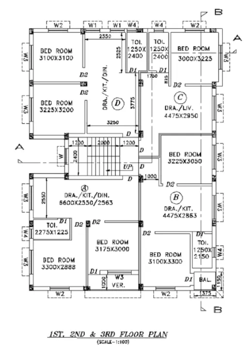
DRAWING 1 - PLAN VIEW
PROCEDURe
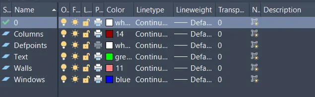
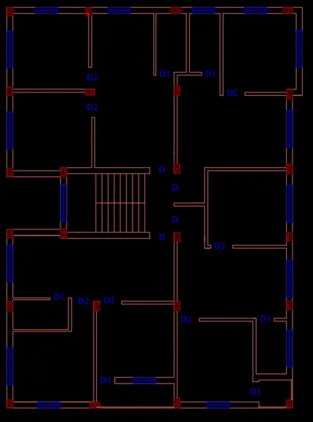
1. The following layers were made accordings to these layers drawings were drawn
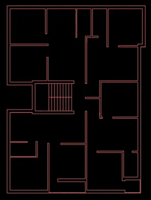
2. The wall layout was drawn. Outer wall is 250mm thk. and inner wall is 110mm thk.
3. Coulmns (with hatching), doors and windows were added using blocks
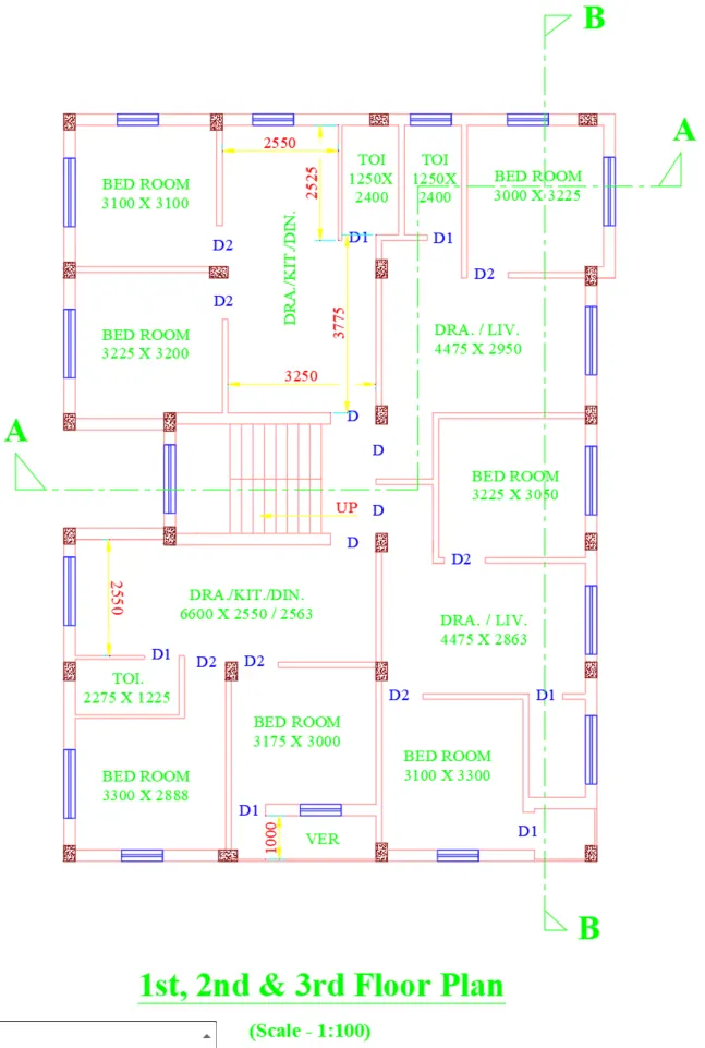
4. The two sections were made, the text was added and the required dimensions were given
NOTE: the lines were drawn using line command ,unknown dimensions were assumed ,using blocks we can create doors and and windows ,we can insert them ,creating the text were requried
result:
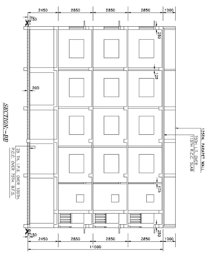
DRAWING 2 - SECTION B -B
PROCEDURE
1. The plan view was rotated as required and the following extension lines were made as per requried dimensions.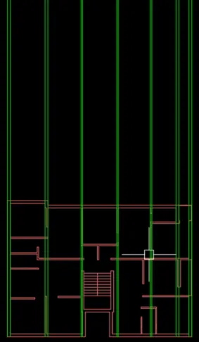
2. The following layout was made and the extension lines were removed and also we can trim them extra lines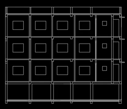
3. The dimensions, text and the leaders were added and the section was completed.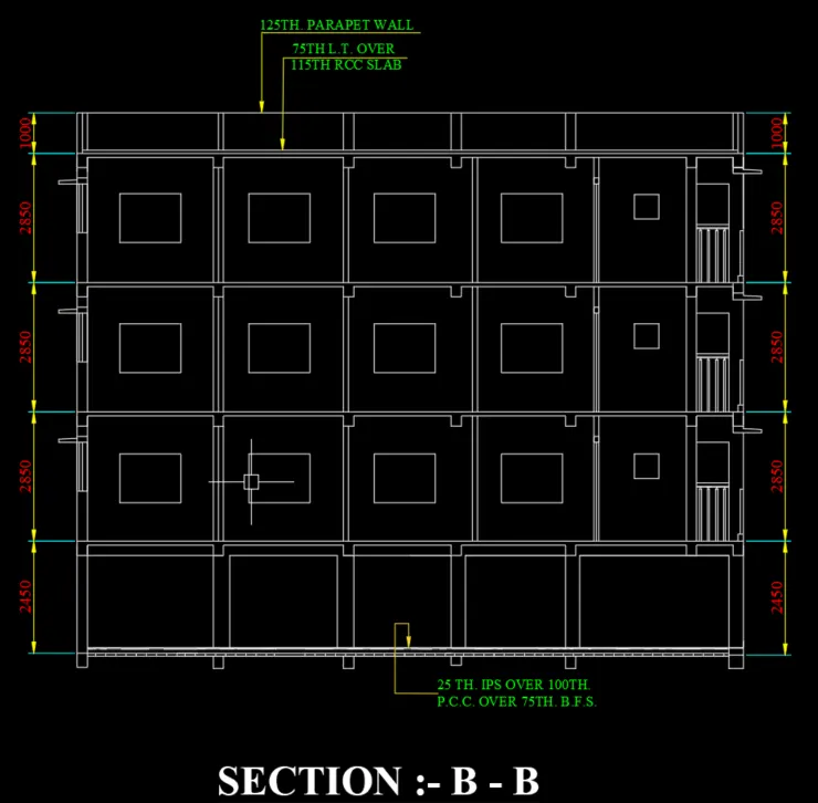
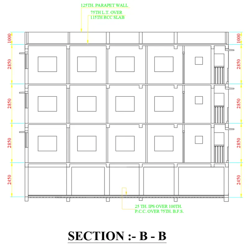
NOTE: the lines were drawn using line command ,unknown dimensions were assumed ,using blocks we can create doors and and windows ,we can insert them ,creating the text were requried
bu using excel command we can take the refrence lines,height of ground level and plinth level has to be taken properly ,weshould undderstand the section bb and draw according to that we should project the lines in a proper way unknown dimendsions has to be assumed.
after finching the one block we can copy them for remning similar blocks
RESULT:
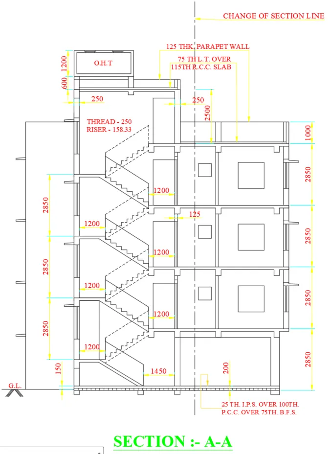
DRAWING 3 - SECTION A -A
PROCEDURE
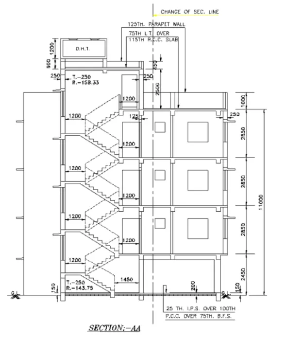
1. Extension lines were made from the plan view and the staircase for a floor was made.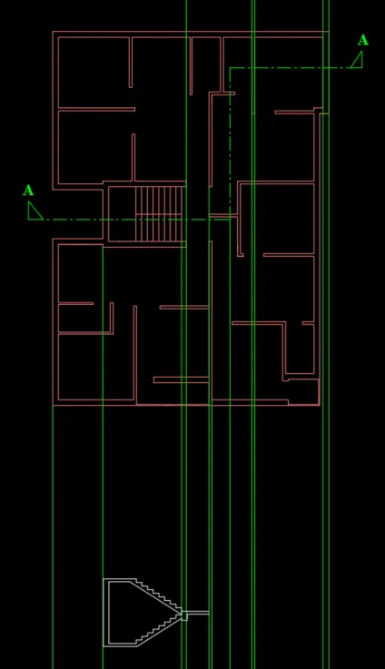
2. Section for a floor was drawn and was copied 2 times for the remaining two floors.
The extension lines that were not required anymore were removed.steps can be drawn with the requried rise step in the given data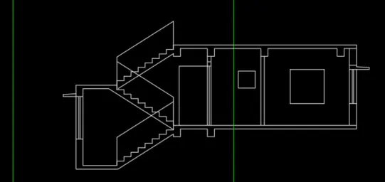
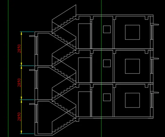
3. The basement and the terrace was made and also the parapet wall with the requried thickness.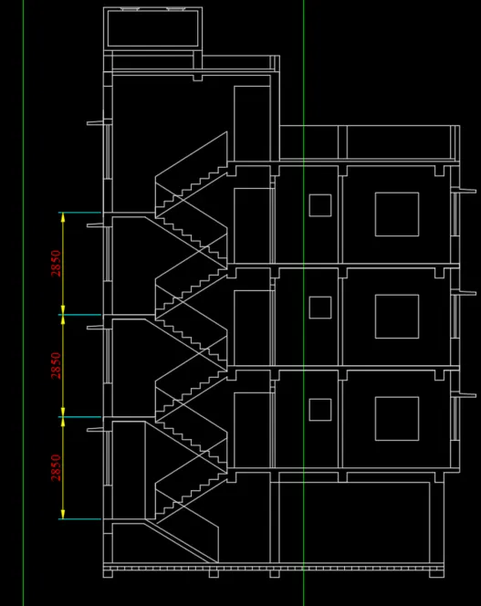
4. The text and the leaders were added and the section was given the dimensions.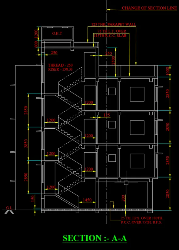
NOTE: the lines were drawn using line command ,unknown dimensions were assumed ,using blocks we can create doors and and windows ,we can insert them ,creating the text were requried
bu using excel command we can take the refrence lines,height of ground level and plinth level has to be taken properly ,weshould undderstand the section bb and draw according to that we should project the lines in a proper way unknown dimendsions has to be assumed.
after finching the one block we can copy them for remning similar blocks
RESULT: