Creating a Layout, Section and Elevation with dimensions using AutoCad
CREATING A LAYOUT,SECTION AND ELEVATION WITH DIMENSION USING AUTOCAD
1. LAYOUT
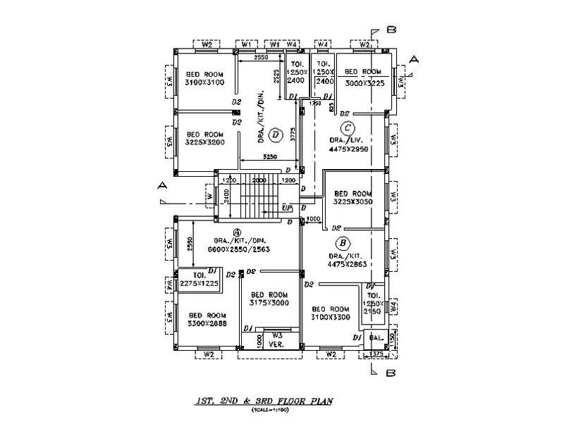
AIM- TO DRAFT THE LAYOUT OF FIRST, SECOND AND THIRD FLOOR PLAN USING AUTOCAD.
INTODUCTION-
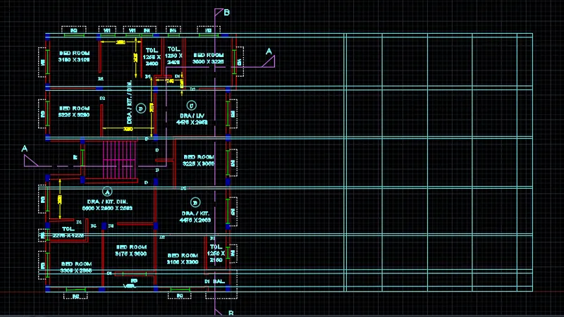
The layout drawing is created using AutoCAD software. The main purpose of this challenge is to be familiar with the annotation and dimension commands.So the layout is drafted step by step and procedure is mentioned below with diagrams and the final result is given.
TOOLS USED-
- LINE - Command for line is L
- CONSTRUCTTION LINE - Command for construction line is XL
- TRIM - Command for trim is TR
- TEXT- Command for text is DTEXT/MTEXT
- DIMENSION - Command for line is Dimension DIM
- OFFSET - Command for offset is O
- FILLET - Command for fillet is F
- SPLINE - Command for spline is SPL
- LAYERS -Command for layer is LA
- CIRCLE - Command for circle is C
- RECTANGLE - Command for the rectangle is REC
- HATCH - Command for hatch is H
- ARC - Command for arc is A
- ARROW - Command for arrow is LE
PROCEDURE-
STEP 1
- Go to START MENU, and select AutoCAD.
- The User Interface of AutoCAD is OPEN.
- Click the start Drawing tab
- The workspace of AutoCad is open,
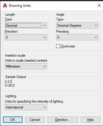
- Enter UNITS in the command box.
- Select DECIMAL in TYPE, 0 in PRECISION, and MILLIMETER in UNITS TO SCALE INSERTED CONTENT.
- Select Angle type as DECIMAL DEGREE, and precision is 0 and direction are Anti-clockwise.
- Press OK.
STEP 2
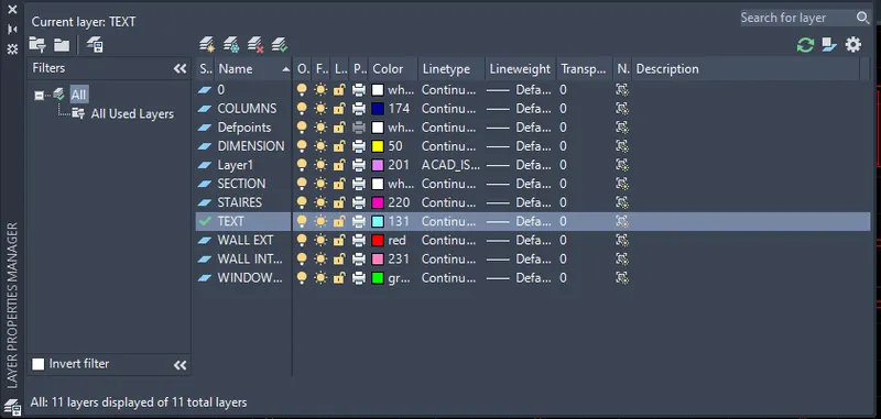
- Click on LAYER PROPERTIES tool or type LA and press ENTER
- A Layer Dialog box will open.
- Click on CREATE NEW LAYER and give a name to layer
- Here, I create a 9 new layer with proper name
- Then, assign a differnt color for differnt layer accourding to our used.
STEP 3
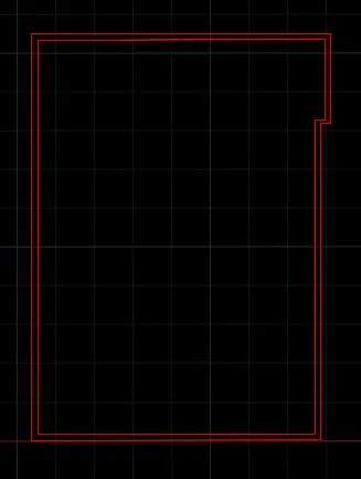
- To create a boundary wall first , select a wall layer from layer dialog box
- to create wall we willl use a construction line and command for construction line is XL ENTER.
- Then press v for vertical line and create one line at any point
- press ESC
- Again press XL and ENTER
- click on HORIZONTAL in command line amd click on screen to draw a one horizontal line
- Select a TRIM tool or press TR and ENTER
- Trim the line beyond the intersection point
- NOW, select a OFFSET tool or type O and press ENTER
- Click on THROUGH in the command line
- Select a horzontal line and Specify the offset distance as 16388
- Now select a vertical line and Specify the offset distance as 11700
- Select a TRIM tool or press TR and ENTER
- Trim the upper and right line just kept the box
- select a OFFSET tool or type O and press ENTER
- Specify offset distance as 250 as a WALL THICKNESS
- PRESS ESC.
STEP 4
- Select the OFFSET from the ribbion or type O and press EENTER
- Click on THROUGH on the command line
- Now click on MULTIPAL in the command line
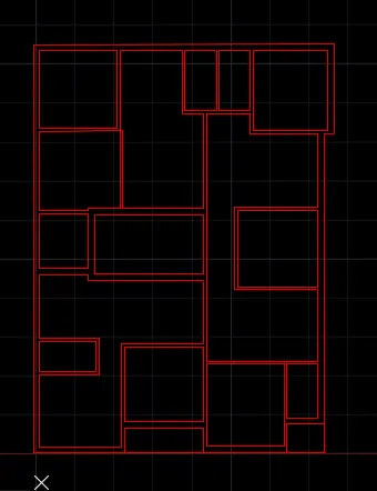
- Specify the Offset distance for first room 3300 in X DIRECTION and 2888 in Y DIRECTION
- To create a wall give the offset of 250mm for external wall and 125mm for internal wall
- Repeat the same process
- Specify the Offset distance for second room 3175 in X DIRECTION and 3000 in Y DIRECTION
- Specify the Offset distance fort third room 3100in X DIRECTION and 3300 in Y DIRECTION
- Specify the Offset distance for the fourth room 1250 in X DIRECTION and 2150 in Y DIRECTION
- Specify the Offset distance for fifth room 4475 in X DIRECTION and 2863 in Y DIRECTION
- Specify the Offset distance for the sixth room 3225 in X DIRECTION and 3050 in Y DIRECTION
- Specify the Offset distance for seventh room 4475 in X DIRECTION and 2950 in Y DIRECTION
- Specify the Offset distance for eight room 3000 in X DIRECTION and 3225 in Y DIRECTION
- Specify the Offset distance for ninh room 1250 in X DIRECTION and 2400 in Y DIRECTION
- Specify the Offset distance for tenth room 3100 in X DIRECTION and 3100 in Y DIRECTION
- Select the TRIM Ccommand from the ribbion and trim the unwanted lines.
STEP 5
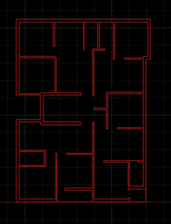
- CREATE A DOOR OPENING
- Select a LINE tool or type L and press ENTER
- Specify a first point as a staring point of door and second point is throught the wall
- Select the OFFSET from the ribbion or type O and press ENTER
- specify the offset distance as size of door and select the last created line
- SIZES OF DOORS ARE -
- D -1000
- D1 - 750
- D2 - 900
STEP 6
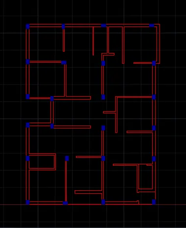
- Select a COLUMN LAYER
- Select a RECTANGLE tool or type a REC and press ENTER
- Click on DIMENSION in the command line
- Specify the length of rectangle is 250 and press enter
- Specif the width of rectangle is 400 and press enter
- Now click on upper click of model space
- Select a HATCH from the ribbion
- Now select the hatch type is soild and click on by layer and slect a layer as column
- now press inside the rectangle
- Now select the rectangle and press it in desired location as shown in image.
STEP 7
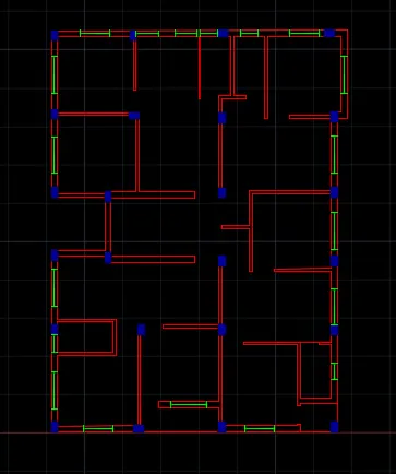
- Select a WINDOWS LAYER
- Select a RECTANGLE tool or type a REC and press ENTER
- Click on DIMENSION in the command line
- Specify the length of rectangle and press enter
- Specif the width of rectangle and press enter
- Select a LINE tool or type L and press ENTER
- Create a line from th mid point of rectangle and trim the length of rectangle
- Select a COPY tool or type CO and press ENTER
- Specify a base point as mid point and place the window at the center of wall.
- SIZES OF WINDOW ARE -
- W -1000
- W1 - 900
- W2 - 1200
- W3 - 1500
- W4 - 700
STEP 8
- Select a STAIR LAYER
- Select a LINE tool or type L and press ENTER
- Specify first point as 1200 from door and
- create a vertical line of 1200
- Select the OFFSET from the ribbion or type O and press ENTER
- specify the offset distance 250 and give it 8 times
- Select a LINE tool or type L and press ENTER
- Specify first point as a mid point of line and second point is mid point of last line
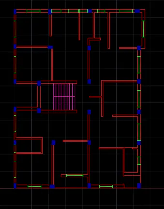
STEP 9
- Select a TEXT LAYER
- Select a multi line text from home > Annotate > multi line text or type MTEXT
- and crete a text accordlingly
- Specify a text font as ARIAL and text size as 250
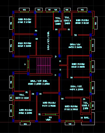
step 10
- Select a DIMENSION LAYER
- Go to dimension style by pessing DIMSTY
- ans Select a overall scal as 1000
RESULT-
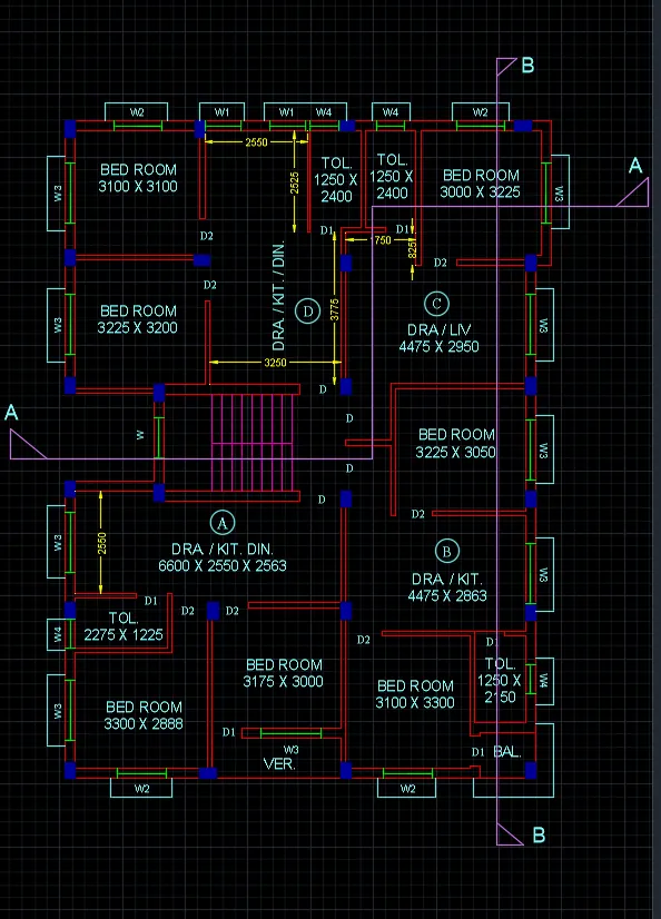
2.SECTION
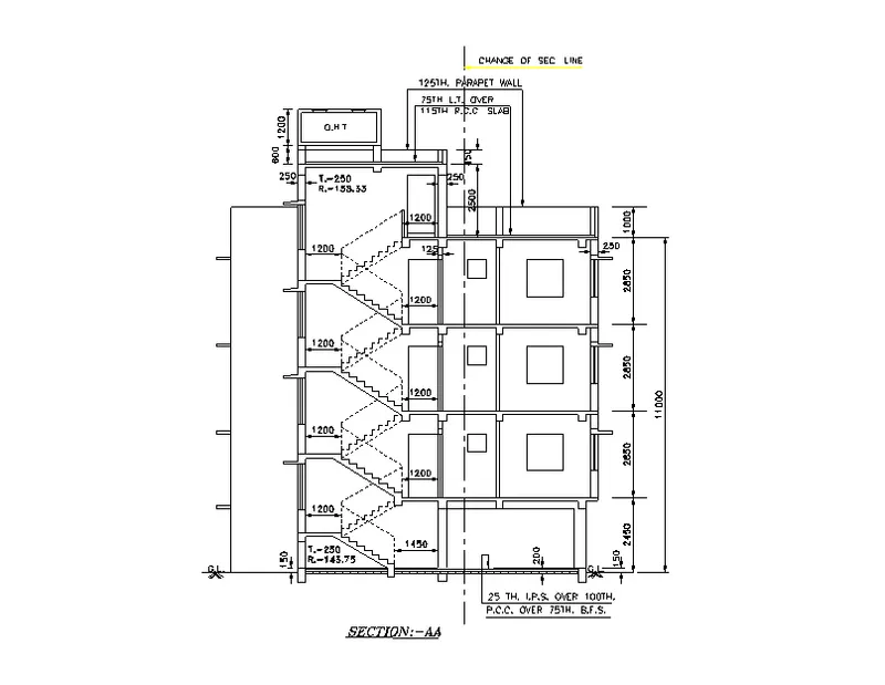
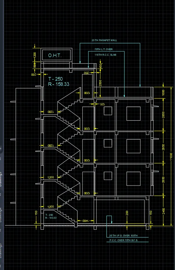
AIM- TO DRAFT THE SECTION AA OF THE FIRST, SECOND, AND THIRD FLOOR PLAN USING AUTOCAD.
INTODUCTION-
The section drawing is created using AutoCAD software. The main purpose of this challenge is to be familiar with the annotation and dimension commands.So the section is drafted step by step and procedure is mentioned below with diagrams and the final result is given.
TOOLS USED-
- LINE - Command for line is L
- CONSTRUCTTION LINE - Command for construction line is XL
- TRIM - Command for trim is TR
- TEXT- Command for text is DTEXT/MTEXT
- DIMENSION - Command for line is Dimension DIM
- OFFSET - Command for offset is O
- FILLET - Command for fillet is F
- SPLINE - Command for spline is SPL
- LAYERS -Command for layer is LA
- CIRCLE - Command for circle is C
- RECTANGLE - Command for the rectangle is REC
- HATCH - Command for hatch is H
- ARC - Command for arc is A
- ARROW - Command for arrow is LE
PROCEDURE-
STEP 1
- To create wall we willl use a construction line and command for construction line is XL ENTER.
- Then press v for vertical line
- press ESC
- Again press XL and ENTER
- click on HORIZONTAL in command line and click on screen to draw a horizontal line
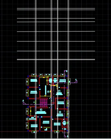
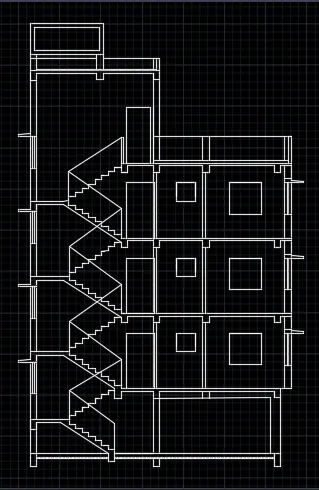
- Get all the projection to draw a section
- Slab thickness was taken as 125 mm
- The height of the floors was taken accordingly as in plan.
- G.F-2450mm
- 1st Floor-2850mm
- 2nd Floor-2850mm
- 3rd Floor-2850mm
STEP 2
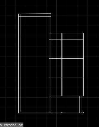
- Select a Trim tool or type TR and press ENTER
- Trime the unwanted lines
STEP 3
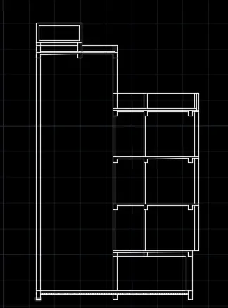
- give thickness to the slab as 125mm
STEP 4
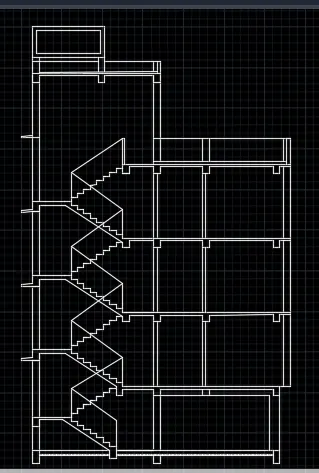
- Design stair
- DIMENSION OF STAIRS ARE -
- TREAD - 250 MM
- RISER - 143.75 ( FROM GROUND FLOOR TO 2ND FLOOR )
- RISER -158.33 ( FORM THIRED FLOOR )
STEP 5
- Creating of DOORS AND WINDOW
- Type XL ENTER nad take all the projection of door
- the window are draw from sill level that is 900
- and ventilator is draw form lentel leevele to downward that is 2100
- SIZES OF DORRS AND WINDOWS ARE -
- W2-1200x1200
- W4-700x500
- D-1000x2000
- Select a DIMENSION LAYER
- Go to dimension style by pessing DIMSTY
- ans Select a overall scal as 1000
RESULT-
3.ELEVATION
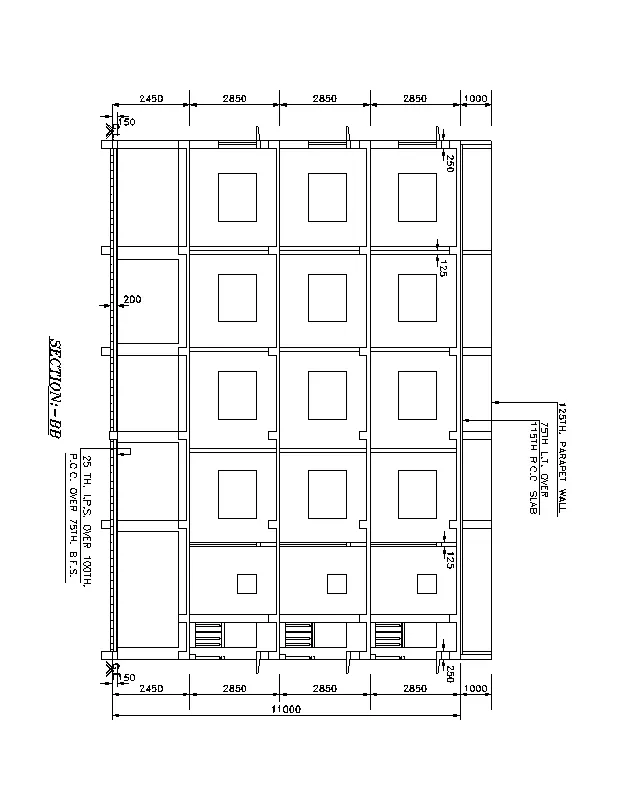
AIM- TO DRAFT THE SECTION BB OF FIRST, SECOND AND THIRD FLOOR PLAN USING AUTOCAD.
INTODUCTION-
The elevation drawing is created using AutoCAD software. The main purpose of this challenge is to be familiar with the annotation and dimension commands.So the elevation is drafted step by step and procedure is mentioned below with diagrams and the final result is given.
TOOLS USED-
- LINE - Command for line is L
- CONSTRUCTTION LINE - Command for the construction line is XL
- TRIM - Command for trim is TR
- TEXT- Command for text is DTEXT/MTEXT
- DIMENSION - Command for line is Dimension DIM
- OFFSET - Command for offset is O
- FILLET - Command for fillet is F
- SPLINE - Command for spline is SPL
- LAYERS -Command for layer is LA
- CIRCLE - Command for circle is C
- RECTANGLE - Command for the rectangle is REC
- HATCH - Command for hatch is H
- ARC - Command for arc is A
- ARROW - Command for arrow is LE
PROCEDURE-
STEP 1
- To create wall we willl use a construction line and command for construction line is XL ENTER.
- Then press v for vertical line
- press ESC
- Again press XL and ENTER
- click on HORIZONTAL in command line and click on screen to draw a horizontal line
- Get all the projection to draw a section
- Slab thickness was taken as 125 mm
- Height of floors are -
- G.F-2450mm
- 1st Floor-2850mm
- 2nd Floor-2850mm
- 3rd Floor-2850mm
STEP 2
- Select a Trim tool or type TR and press ENTER
- Trime the unwanted lines
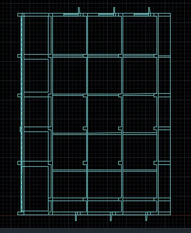
- Create a sunshade using line tool
STEP 3
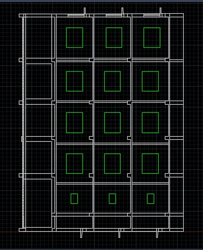
- Creating WINDOW
- Type XL ENTER nad take all the projection of door
- the window are draw from siLl level that is 900
- and ventilator is draw form lentel leevele to downward that is 2100
- SIZES OF WINDOWS ARE -
- W3-1500x1200
- W4-700x500
STEP 4
- Select a DIMENSION LAYER
- Go to dimension style by pessing DIMSTY
- ans Select a overall scal as 1000
RESULT-
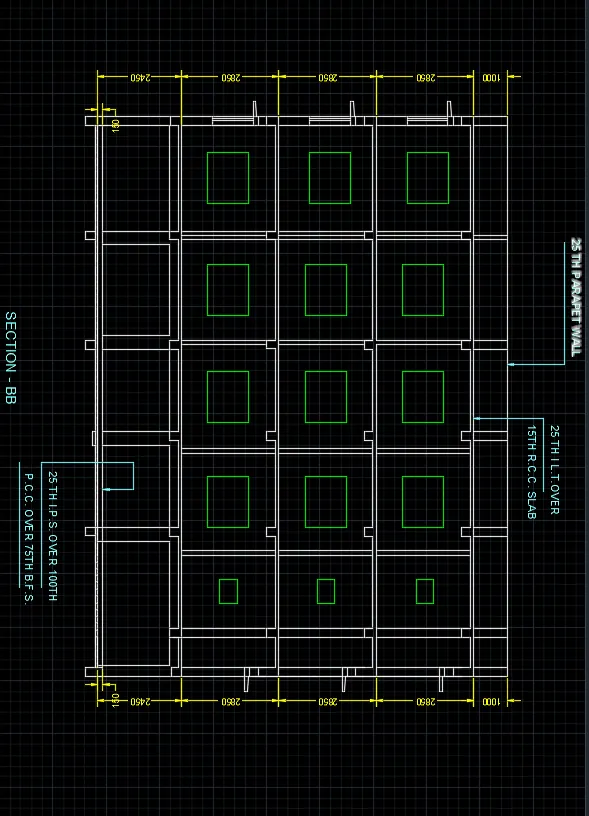
FINAL RESULT-