Creating a Layout, Section and Elevation with dimensions using AutoCad
1)
AIM:
To create the plan and sections as shown in the fiqure. Use proper dimension techniquesa and
dimension styles to document the project using AUTOCAD
PROCEDURE:
STEP 1:
- in the command prompt type units > mm.
- in the command prompt type limmax > 100,100
- in command prompt type limits > 0,0
- in the command prompt type zoom > a
STEP 2:
- in the command prompt type xl to draft the infinite line
- in the command prompt type offset to offset it to disired distance
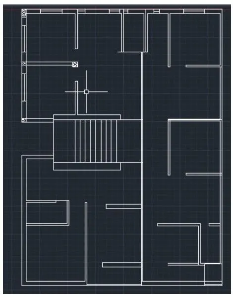
- with the command lines,offset and trim windows are drawn
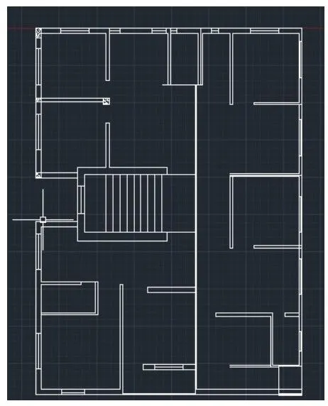
- in the ribbon tab > annotate > mtext ( to text the annotations )
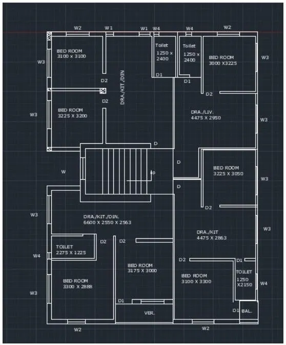
- in the command prompt type LN ( linetype ) to get dotted lines
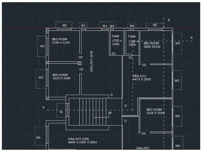
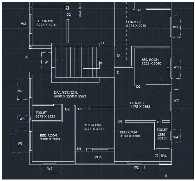
- in the ribbon bar > dimensions > to give the plan
- in the ribbon bar > hatch > sand
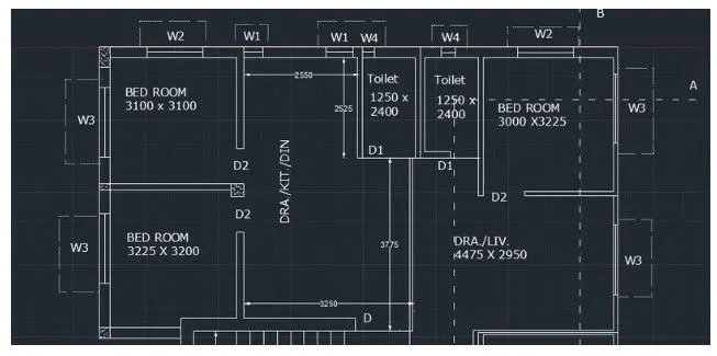
FINAL RESULT:
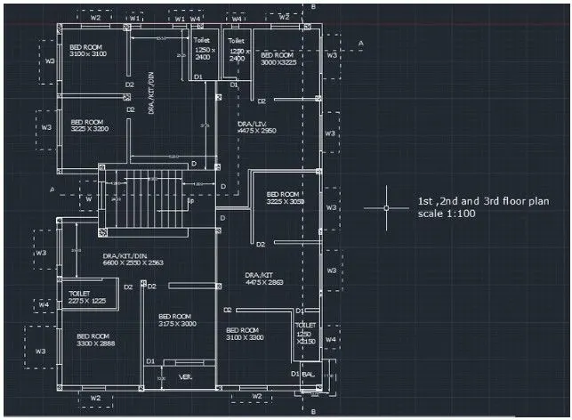
1)B
AIM:
- To create section A-A of the previous plan
PROCEDURE:
- in the command prompt type rec to draft the rectangle of dimensions 2745 x 1200
- in the command prompt type offset and offset it to the required distance
- in the command prompt type l to draft the required lines
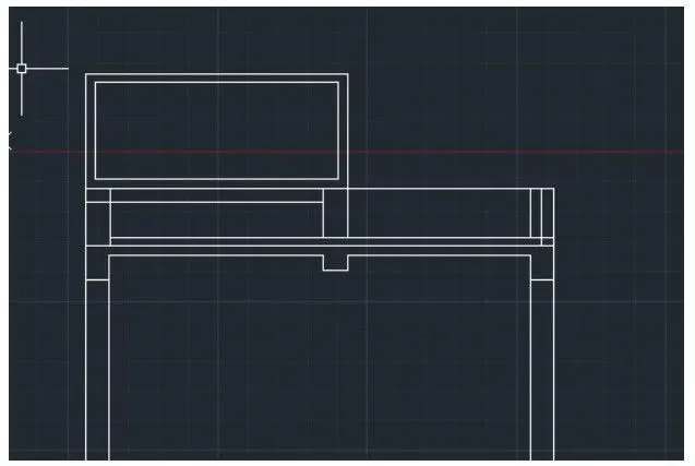
- in the command prompt type LT( to get the dotted lines )
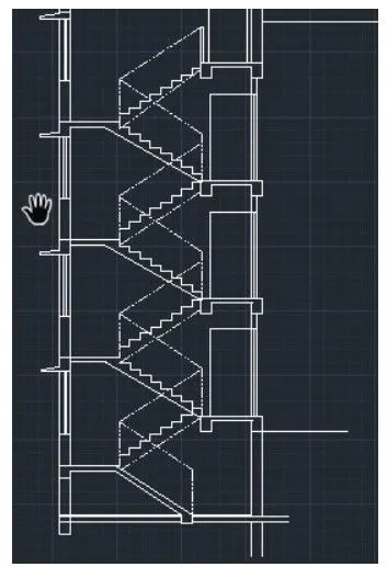
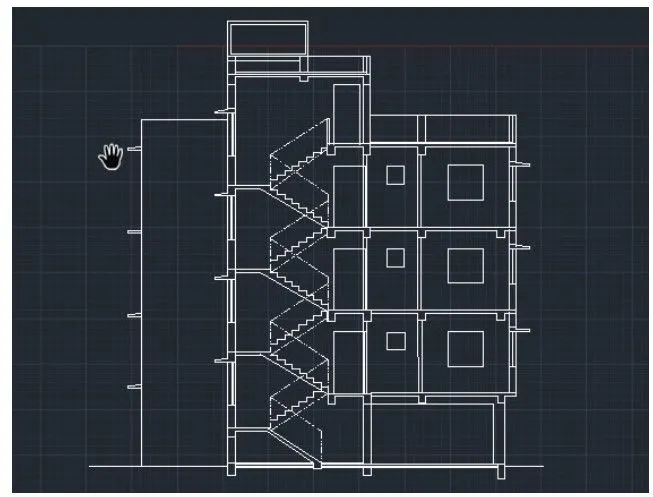
- in the ribbon tab > annotation > to text the plan
- in the ribbon tab > dimensions > to give the dimensions to the plan
- in the command prompt type leader to type the given text and dimensions
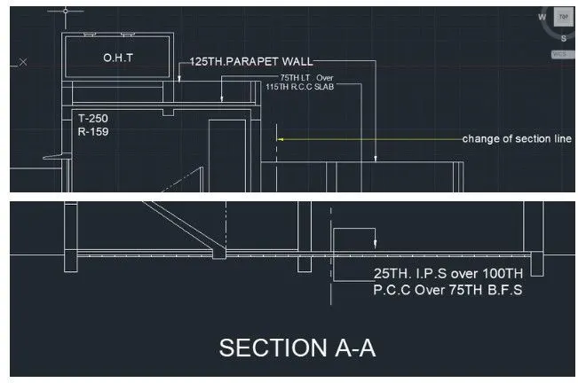
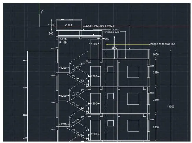
FINAL RESULTS:
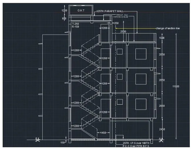
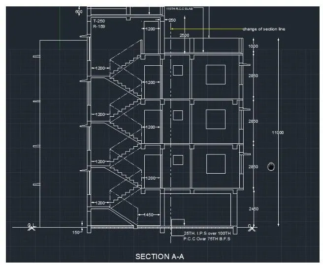
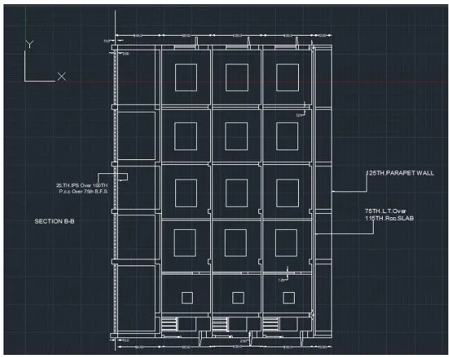
1)C
AIM:
- to create section B-b of the previous plan
PROCEDURE:
- in the command prompt type XL to draw the infinite lines
- in the command prompt type offset to offset the infinite lines for the desired distance
- in the command prompt type rec to draw the rectangle
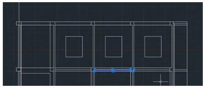
- in the command prompt type line to draft the desired lines
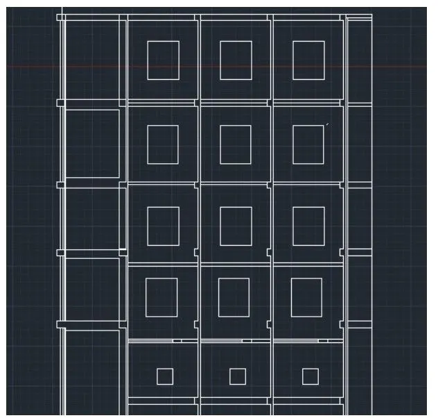
- in the command prompt type dimensions to give the dimensions
- in the command prompt type leader to give the annotations for the plan
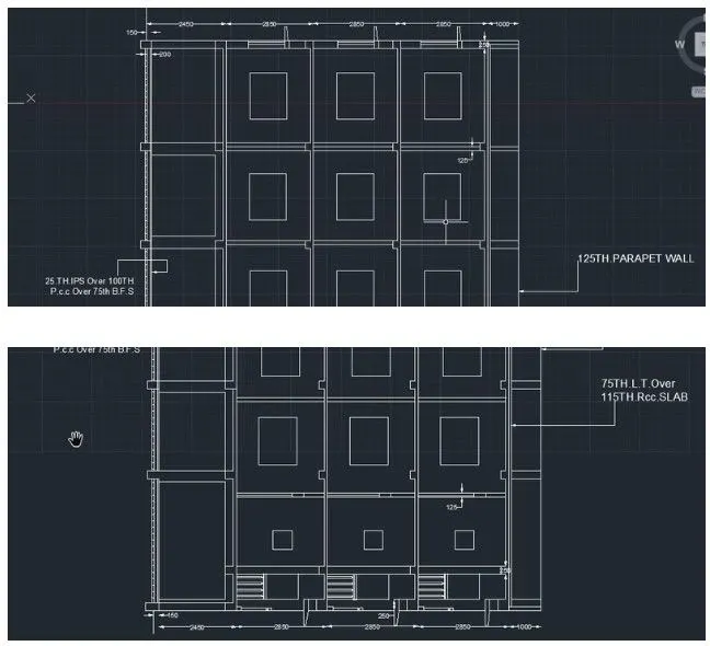
FINAL RESULT: