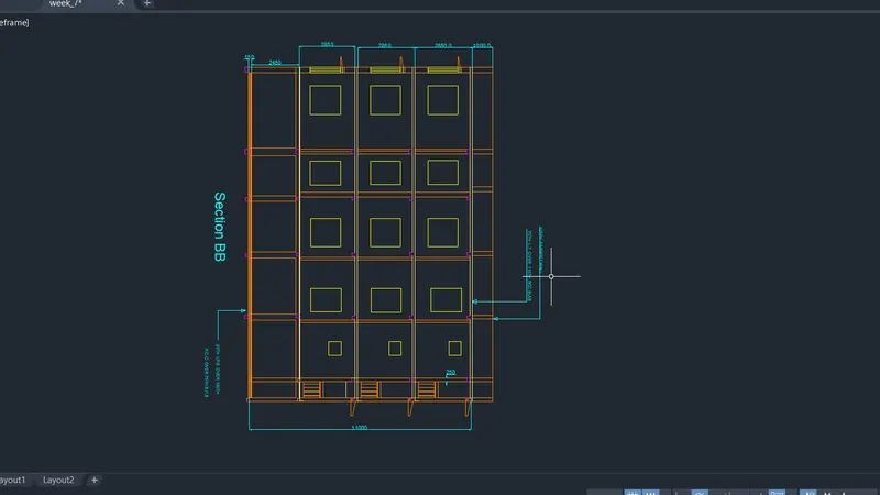
Creating a Layout, Section and Elevation with dimensions using AutoCad
Aim: To create the floor plan, section AA and section BB as shown in the figure
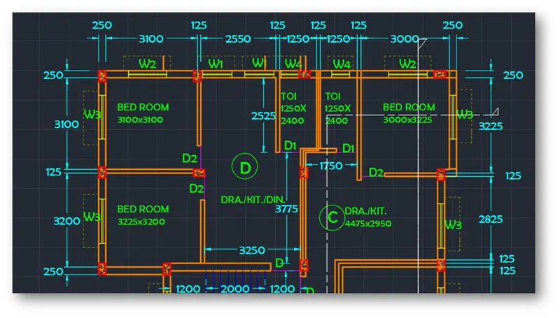
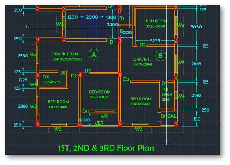
Introduction: The floor plan given is of an apartment building with same plan for 1st, 2nd and 3rd floors. Each floor consists of four houses, three two-bedroom flats and one single bedroom flat each with kitchen and living room. Each flat has only one common bathroom. Stairs connect all the floors. Stair dimensions are taken from stair section view. The top two flats are given as flat C and flat D respectively. The section views AA and BB are drawn using projection lines from plan drawing. Dimensions and text is placed accordingly. The dimensions of doors and windows are assumed as follows
- Main Door or D as 1000mm X 2200mm
- Door 1 or D1 as 700mm X 2000mm
- Door 2 or D2 as 800mm X 2000mm
- Window 1 or W1 as 1000mm X 1400mm
- Window 2 or W2 as 1300mm X 1400mm
- Window 3 or W3 as 1500mm X 1400mm
- Window 4 or W4 as 600mm X 700mm.
Procedure:
Open AutoCAD
In Startup settings start from scratch select metric (MilliMeters)
Open grid and snap settings
- Change snap and grid spacing to 100
- Change major line every grid line to 10
- Turnoff adaptive grid
Type ‘un’ in command box and press enter
Change units’ type to decimal and precision to 0.00 and insertion scale to millimeters
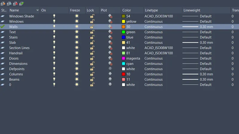
Step 1: Creating Layers
Open Layer properties and create new layers by clicking on new layer or right click on any layer and select new layer to create new layer
Layers are created as follows
Step 2: Creating Flat C and D
Type xline in command box and press enter
- Specify a point or [Hor: Ver: Ang: Bisect: Offset]: Click on hor and select any point on the screen
Type xline in command box and press enter
- Specify a point or [Hor : Ver : Ang : Bisect : Offset] : Click on ver and select any point on the horizontal xline
Type ‘o’ or offset and press enter or click offset from the modify tool bar
- Specify offset distance: Type 250 and press enter
- Select object to offset: Select horizontal xline and click on bottom
- Select object to offset: Select vertical xline and click on right
Type ‘o’ or offset and press enter or click offset from the modify tool bar
- Specify offset distance: Type 3100 and press enter
- Select object to offset: Select the vertical offset xline of wall thickness and click on right
Type ‘o’ or offset and press enter or click offset from the modify tool bar
- Specify offset distance: Type 125 and press enter
- Select object to offset: Select last offset to give wall thickness and click on right
Type ‘o’ or offset and press enter or click offset from the modify tool bar
- Specify offset distance: Type 2550 and press enter
- Select object to offset: Select the last vertical offset line and click on right
Type ‘o’ or offset and press enter or click offset from the modify tool bar
- Specify offset distance: Type 125 and press enter
- Select object to offset: Select last offset to give wall thickness and click on right
Type ‘o’ or offset and press enter or click offset from the modify tool bar
- Specify offset distance: Type 1250 and press enter
- Select object to offset: Select the last vertical offset line and click on right
Type ‘o’ or offset and press enter or click offset from the modify tool bar
- Specify offset distance: Type 125 and press enter
- Select object to offset: Select last offset to give wall thickness and click on right
Type ‘o’ or offset and press enter or click offset from the modify tool bar
- Specify offset distance: Type 1250 and press enter
- Select object to offset: Select the last vertical offset line and click on right
Type ‘o’ or offset and press enter or click offset from the modify tool bar
- Specify offset distance: Type 125 and press enter
- Select object to offset: Select last offset to give wall thickness and click on right
Type ‘o’ or offset and press enter or click offset from the modify tool bar
- Specify offset distance: Type 3000 and press enter
- Select object to offset: Select the last vertical offset line and click on right
Type ‘o’ or offset and press enter or click offset from the modify tool bar
- Specify offset distance: Type 250 and press enter
- Select object to offset: Select last offset to give wall thickness and click on right
Trim off outer portions and extra portions as shown in the figure
Type ‘o’ or offset and press enter or click offset from the modify tool bar
- Specify offset distance: Type 3100 and press enter
- Select object to offset: Select the horizontal offset xline of wall thickness and click on bottom
Type ‘o’ or offset and press enter or click offset from the modify tool bar
- Specify offset distance: Type 125 and press enter
- Select object to offset: Select horizontal offset xline to give wall thickness and click on bottom
Type ‘o’ or offset and press enter or click offset from the modify tool bar
- Specify offset distance: Type 3200 and press enter
- Select object to offset: Select the last offset line of wall thickness and click on bottom
Type ‘o’ or offset and press enter or click offset from the modify tool bar
- Specify offset distance: Type 250 and press enter
- Select object to offset: Select last offset line to give wall thickness and click on bottom
Draw a line connecting the two bathrooms
Type ‘o’ or offset and press enter or click offset from the modify tool bar
- Specify offset distance: Type 2400 and press enter
- Select object to offset: Select the line drawn above of wall thickness and click on bottom
Type ‘o’ or offset and press enter or click offset from the modify tool bar
- Specify offset distance: Type 125 and press enter
- Select object to offset: Select last offset line to give wall thickness and click on bottom
Type ‘o’ or offset and press enter or click offset from the modify tool bar
- Specify offset distance: Type 3775 and press enter
- Select object to offset: Select the last offset line of wall thickness and click on bottom
Type ‘o’ or offset and press enter or click offset from the modify tool bar
- Specify offset distance: Type 250 and press enter
- Select object to offset: Select the last offset line and give wall thickness and click on bottom
Extend that last two offset lines till the left most wall edge, so that it can be trimmed off later
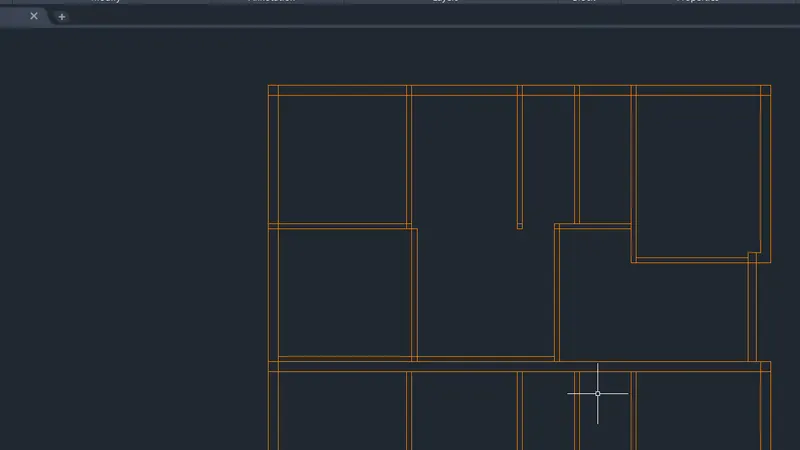
Draw a line at the inner top edge of bedroom of flat C
Type ‘o’ or offset and press enter or click offset from the modify tool bar
- Specify offset distance: Type 3225 and press enter
- Select object to offset: Select the line drawn earlier and click on bottom
Type ‘o’ or offset and press enter or click offset from the modify tool bar
- Specify offset distance: Type 125 and press enter
- Select object to offset: Select the last offset line and click on bottom
Type ‘o’ or offset and press enter or click offset from the modify tool bar
- Specify offset distance: Type 2950 and press enter
- Select object to offset: Select the last offset line and click on bottom
Type ‘o’ or offset and press enter or click offset from the modify tool bar
- Specify offset distance: Type 4475 and press enter
- Select object to offset: Select the left edge of the living room in flat C and click on right
Adjust the wall of flat C living room as shown in figure
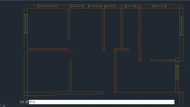
The final figure with door openings and windows is as follows
Step 3: Creating stairs and flat A and flat B
Stairs
Type ‘o’ or offset and press enter or click offset from the modify tool bar
- Specify offset distance: Type 2400 and press enter
- Select object to offset: Select the bottom outer wall edge of flat D and click on bottom
Type ‘o’ or offset and press enter or click offset from the modify tool bar
- Specify offset distance: Type 250 and press enter
- Select object to offset: Select the last offset line and click on bottom
Using line command draw lines connecting the edges of columns
Using line command draw a line at the left edge of stair way
Type ‘o’ or offset and press enter or click offset from the modify tool bar
- Specify offset distance: Type 1200 and press enter
- Select object to offset: Select the line drawn earlier and click on left
Type ‘o’ or offset and press enter or click offset from the modify tool bar
- Specify offset distance: Type 2000 and press enter
- Select object to offset: Select the line drawn earlier and click on left
Type ‘o’ or offset and press enter or click offset from the modify tool bar
- Specify offset distance: Type 250 and press enter
- Select object to offset: Select the last offset line and click on right
- Select object to offset: Select the last offset line and click on right
- Select object to offset: Select the last offset line and click on right
- Select object to offset: Select the last offset line and click on right
- Select object to offset: Select the last offset line and click on right
- Select object to offset: Select the last offset line and click on right
- Select object to offset: Select the last offset line and click on right
Draw a line connecting midpoints of the stairs
Using line command draw the left wall with respect to stairs
Change the layer to stairs layer in the layer dropdown
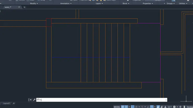
Flat A and B
Using line command draw the top wall of flat B starting from the middle of stairway
Offset the wall line drawn with 250 mm to bottom
Type ‘o’ or offset and press enter or click offset from the modify tool bar
- Specify offset distance: Type 3050 and press enter
- Select object to offset: Select the last offset line at top and click on bottom
Type ‘o’ or offset and press enter or click offset from the modify tool bar
- Specify offset distance: Type 125 and press enter
- Select object to offset: Select the last offset line and click on bottom
Type ‘o’ or offset and press enter or click offset from the modify tool bar
- Specify offset distance: Type 2863 and press enter
- Select object to offset: Select the last offset line at top and click on bottom
Type ‘o’ or offset and press enter or click offset from the modify tool bar
- Specify offset distance: Type 125 and press enter
- Select object to offset: Select the last offset line and click on bottom
Draw a line using line command at the right wall edge of top bedroom of flat B on vertical x line
Type ‘o’ or offset and press enter or click offset from the modify tool bar
- Specify offset distance: Type 3225 and press enter
- Select object to offset: Select the line drawn earlier at right wall and click on left
Type ‘o’ or offset and press enter or click offset from the modify tool bar
- Specify offset distance: Type 125 and press enter
- Select object to offset: Select the last offset line and click on left
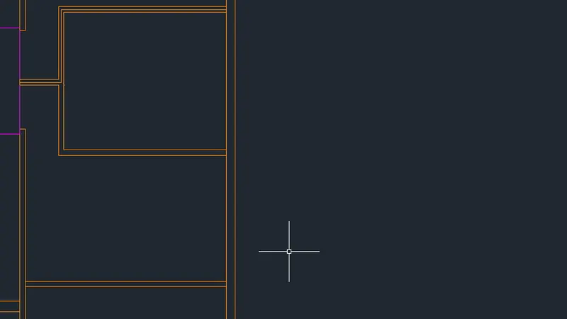
Type ‘o’ or offset and press enter or click offset from the modify tool bar
- Specify offset distance: Type 2563 and press enter
- Select object to offset: Select the bottom edge of stair way and click on bottom
Type ‘o’ or offset and press enter or click offset from the modify tool bar
- Specify offset distance: Type 125 and press enter
- Select object to offset: Select the last offset line and click on bottom
Type ‘o’ or offset and press enter or click offset from the modify tool bar
- Specify offset distance: Type 3000 and press enter
- Select object to offset: Select the bottom edge of stair way and click on bottom
Type ‘o’ or offset and press enter or click offset from the modify tool bar
- Specify offset distance: Type 250 and press enter
- Select object to offset: Select the last offset line and click on bottom
Type ‘o’ or offset and press enter or click offset from the modify tool bar
- Specify offset distance: Type 2550 and press enter
- Select object to offset: Select the bottom edge of wall left of stairway and click on bottom
Type ‘o’ or offset and press enter or click offset from the modify tool bar
- Specify offset distance: Type 125 and press enter
- Select object to offset: Select the last offset line and click on bottom
Trim off extra portions
Type ‘o’ or offset and press enter or click offset from the modify tool bar
- Specify offset distance: Type 1225 and press enter
- Select object to offset: Select the last offset line and click on bottom
Type ‘o’ or offset and press enter or click offset from the modify tool bar
- Specify offset distance: Type 125 and press enter
- Select object to offset: Select the last offset line and click on bottom
Type ‘o’ or offset and press enter or click offset from the modify tool bar
- Specify offset distance: Type 2888 and press enter
- Select object to offset: Select the last offset line and click on bottom
Type ‘o’ or offset and press enter or click offset from the modify tool bar
- Specify offset distance: Type 250 and press enter
- Select object to offset: Select the last offset line and click on bottom
Trim off extra portions of xlines drawn at different points
Draw line at the left inner wall edge of flat A
Type ‘o’ or offset and press enter or click offset from the modify tool bar
- Specify offset distance: Type 2275 and press enter
- Select object to offset: Select the line drawn earlier and click on right
Type ‘o’ or offset and press enter or click offset from the modify tool bar
- Specify offset distance: Type 125 and press enter
- Select object to offset: Select the last offset line and click on right
Type ‘o’ or offset and press enter or click offset from the modify tool bar
- Specify offset distance: Type 3300 and press enter
- Select object to offset: Select the line drawn earlier and click on right
Type ‘o’ or offset and press enter or click offset from the modify tool bar
- Specify offset distance: Type 125 and press enter
- Select object to offset: Select the last offset line and click on right
Trim extra portions of bathroom wall and main wall in the bedroom
Draw a line connecting right wall edge of bedroom in flat B
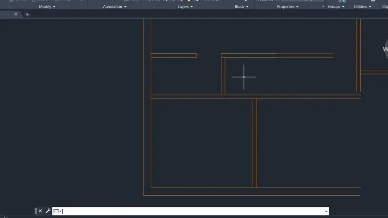
Create the door openings as per the dimensions from introduction
Create window openings as per step 4 and dimensions from the introduction
Assign layers accordingly as per layers cretaed
The final figure after creating walls and columns of flat A and B along with stairs is
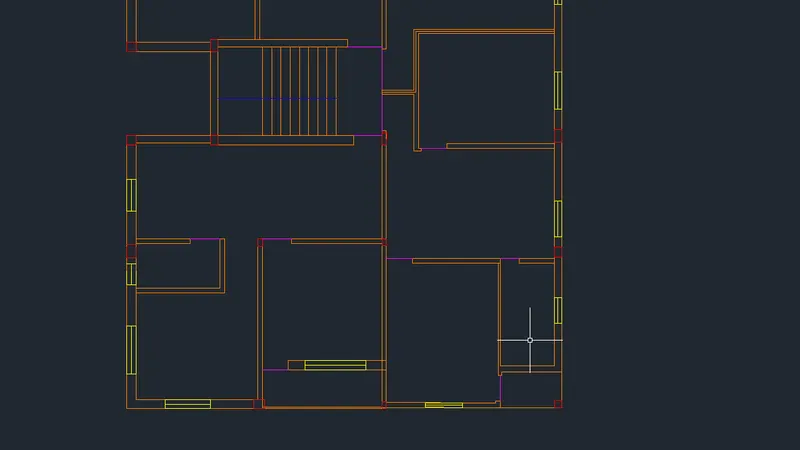
Step 4: Creating doors and windows
Creating Windows
Window 1
Using line command draw a line across the wall
Offset the line through a distance of 1000
Using line command draw two lines connecting the above drawn lines at the middle
All windows are created with same procedure and dimensions from the introduction
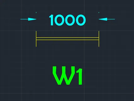
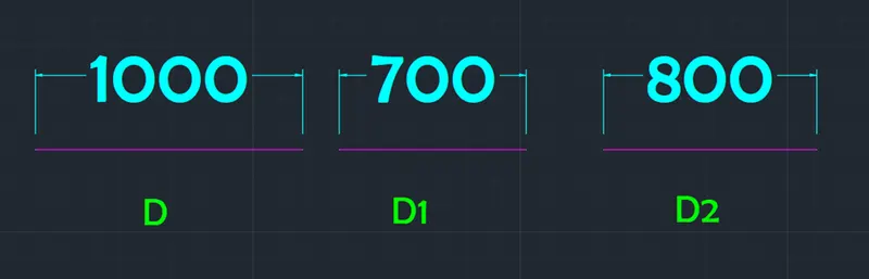
Doors and windows are copied from creation point and pasted where ever required
Use DIMBREAK command where ever dimensions are intersecting
Hatching is done for columns with hatch pattern AR-CONC
Window shades are created around all windows using ISO dash space - - - - - - - - line type
The final result of step 2, 3 and 4 is as follows
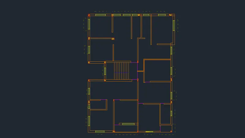
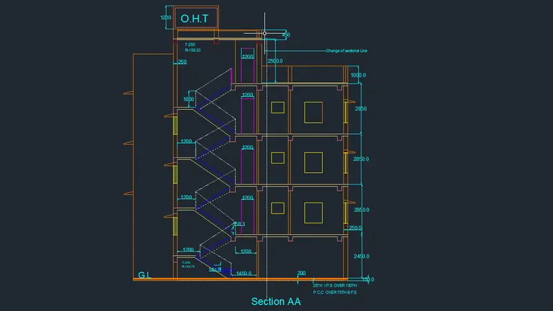
Step 5: Creating Section AA
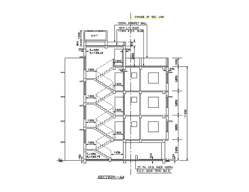
Using line command draw projection lines for all wall edges, window edges, and stairway limits along the section line AA as shown beloW
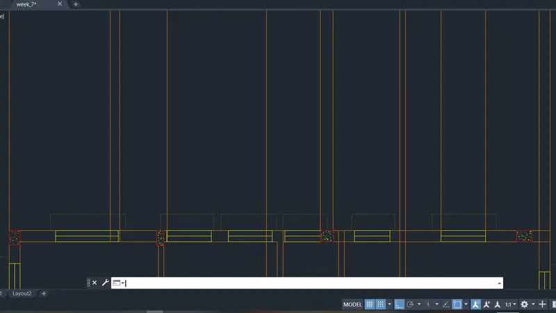
Using line command draw line at certain offset distance from the plan view, connecting all the projection lines
Type ‘o’ or offset and press enter or click offset from the modify tool bar
- Specify offset distance: Type 150 and press enter
- Select object to offset: Select the line drawn earlier and click on top
Type ‘o’ or offset and press enter or click offset from the modify tool bar
- Specify offset distance: Type 50 and press enter
- Select object to offset: Select the line drawn earlier and click on bottom
Type ‘o’ or offset and press enter or click offset from the modify tool bar
- Specify offset distance: Type 25 and press enter
- Select object to offset: Select the top offset line and click on bottom
Type ‘o’ or offset and press enter or click offset from the modify tool bar
- Specify offset distance: Type 100 and press enter
- Select object to offset: Select the top offset line and click on bottom
Type ‘o’ or offset and press enter or click offset from the modify tool bar
- Specify offset distance: Type 2450 and press enter
- Select object to offset: Select the line drawn at the beginning and click on top
Type ‘o’ or offset and press enter or click offset from the modify tool bar
- Specify offset distance: Type 2850 and press enter
- Select object to offset: Select the last offset line and click on top
- Select object to offset: Select the last offset line and click on top
- Select object to offset: Select the last offset line and click on top
Type ‘o’ or offset and press enter or click offset from the modify tool bar
- Specify offset distance: Type 115 and press enter
- Select object to offset: Select the last offset line and click on bottom
- Select object to offset: Select the last offset line and click on bottom
- Select object to offset: Select the last offset line and click on bottom
Trim off extra portions
Change the current layer to window layer
Draw a line connecting two window line projections at the first-floor level
Type ‘o’ or offset and press enter or click offset from the modify tool bar
- Specify offset distance: Type 800 and press enter
- Select object to offset: Select the line drawn and click on top
Using rectangle command draw a window with 1300X1400 as per W2 dimensions
Using rectangle command draw a window with 600X700 as per W4 dimensions
Copy the rectangles to all the floors as shown in figure
Trim off the outer extra potions
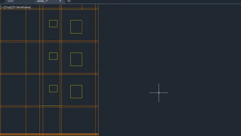
Using rectangle command draw beams of size 250X250 above all the walls
Draw the windows on the right wall in the plan according to step 4 window drawing method as shown in figure along with window shades
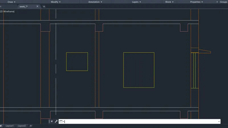
Change the layer to stairs
Draw an offset point of 1450mm from the right edge of stair way for the ground floor stairs
Draw an offset point of 1200mm from the left edge of stair way for the ground floor stairs
Type ‘l’ or line in command box and press enter
- Specify first point: Turn on OSNAP and click on the bottom point of the offset line drawn at 1450 from the right edge
- Specify next point: Turn on ortho mode and keep curser to top and type 143.75 and press enter
- Specify next point: Turn on ortho mode and keep curser to left and type 250 and press enter
- Specify next point: Turn on ortho mode and keep curser to top and type 143.75 and press enter
- Specify next point: Turn on ortho mode and keep curser to left and type 250 and press enter
Repeat the same process until landing is reached
Drawn land slab and stair way slab using line command
Type ‘l’ or line in command box and press enter
- Specify first point: Turn on OSNAP and click on the bottom point of the offset line drawn at 1200 from the right edge
- Specify next point: Turn on ortho mode and keep curser to top and type 143.75 and press enter
- Specify next point: Turn on ortho mode and keep curser to right and type 250 and press enter
- Specify next point: Turn on ortho mode and keep curser to top and type 143.75 and press enter
- Specify next point: Turn on ortho mode and keep curser to right and type 250 and press enter
Repeat the same process until first floor is reached
For the rest of the floor change the raiser height to 158.33
Using Line command drawn the hand rail using line type ISO dash space and line type scale 8.
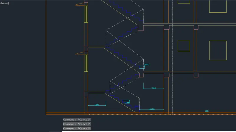
Using rectangle command draw door of flat D at each floor entrance as shown in the figure above
Type ‘o’ or offset and press enter or click offset from the modify tool bar
- Specify offset distance: Type 75 and press enter
- Select object to offset: Select the top edge and click on top
Type ‘o’ or offset and press enter or click offset from the modify tool bar
- Specify offset distance: Type 1000 and press enter
- Select object to offset: Select the top edge and click on top
Type ‘o’ or offset and press enter or click offset from the modify tool bar
- Specify offset distance: Type 2500 and press enter
- Select object to offset: Select the top edge and click on top
Type ‘o’ or offset and press enter or click offset from the modify tool bar
- Specify offset distance: Type 450 and press enter
- Select object to offset: Select the last offset line and click on top
Trim the right portions of lines right of roof stairs and door
Draw the top tank using rectangle command
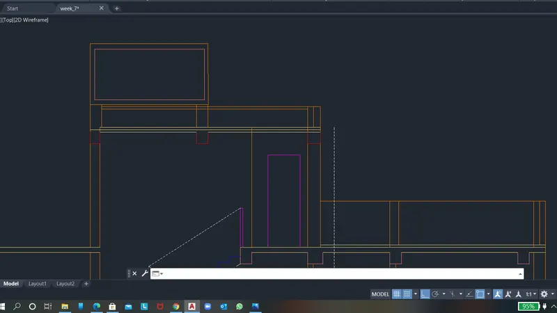
Trim off all the extra portions
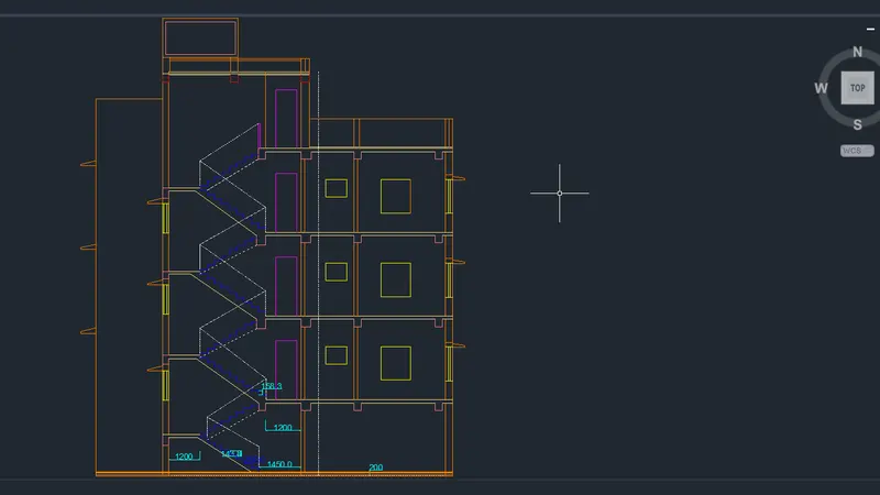
The final figure of section AA after assigning all the layers is as follows
Step 6: Section BB
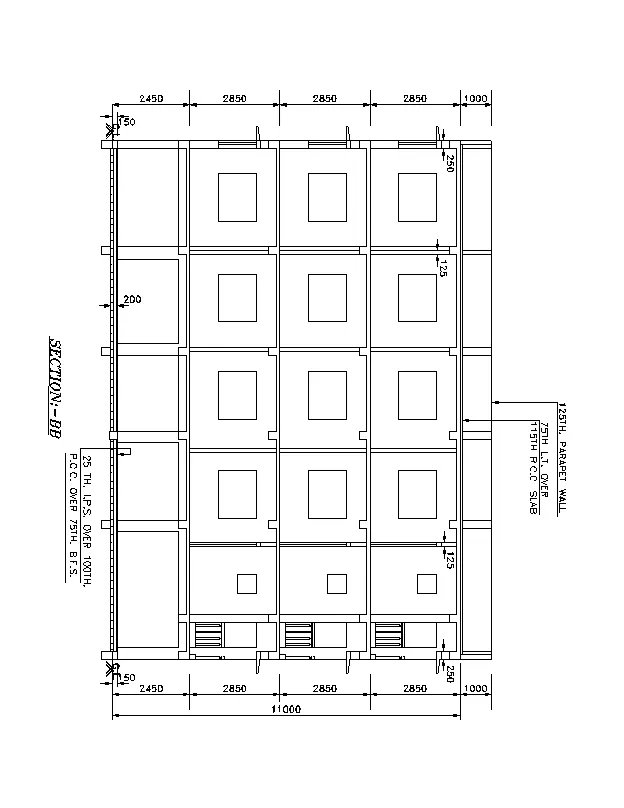
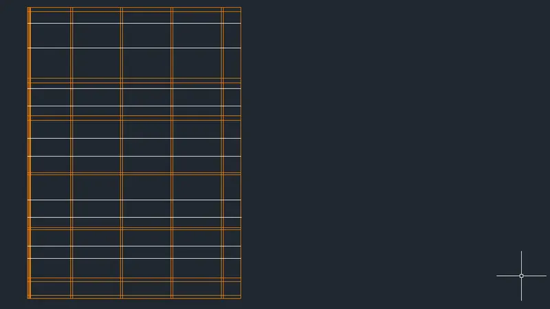
Using line command draw projection lines for all wall edges and window edges along the section line BB as shown below
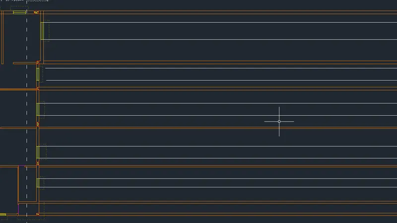
Using line command draw line at certain offset distance from the plan view, connecting all the projection lines
Type ‘o’ or offset and press enter or click offset from the modify tool bar
- Specify offset distance: Type 150 and press enter
- Select object to offset: Select the line drawn earlier and click on right
Type ‘o’ or offset and press enter or click offset from the modify tool bar
- Specify offset distance: Type 50 and press enter
- Select object to offset: Select the line drawn earlier and click on left
Type ‘o’ or offset and press enter or click offset from the modify tool bar
- Specify offset distance: Type 25 and press enter
- Select object to offset: Select the top offset line and click on left
Type ‘o’ or offset and press enter or click offset from the modify tool bar
- Specify offset distance: Type 100 and press enter
- Select object to offset: Select the top offset line and click on left
Type ‘o’ or offset and press enter or click offset from the modify tool bar
- Specify offset distance: Type 2450 and press enter
- Select object to offset: Select the line drawn at the beginning and click on right
Type ‘o’ or offset and press enter or click offset from the modify tool bar
- Specify offset distance: Type 2850 and press enter
- Select object to offset: Select the last offset line and click on right
- Select object to offset: Select the last offset line and click on right
- Select object to offset: Select the last offset line and click on right
Type ‘o’ or offset and press enter or click offset from the modify tool bar
- Specify offset distance: Type 115 and press enter
- Select object to offset: Select the last offset line and click on left
- Select object to offset: Select the last offset line and click on left
- Select object to offset: Select the last offset line and click on left
Type ‘o’ or offset and press enter or click offset from the modify tool bar
- Specify offset distance: Type 1000 and press enter
- Select object to offset: Select the left most edge and click on right
Trim off extra portions
Change the current layer to window layer
Type ‘o’ or offset and press enter or click offset from the modify tool bar
- Specify offset distance: Type 800 and press enter
- Select object to offset: Select the bottom floor line of first floor and click on top
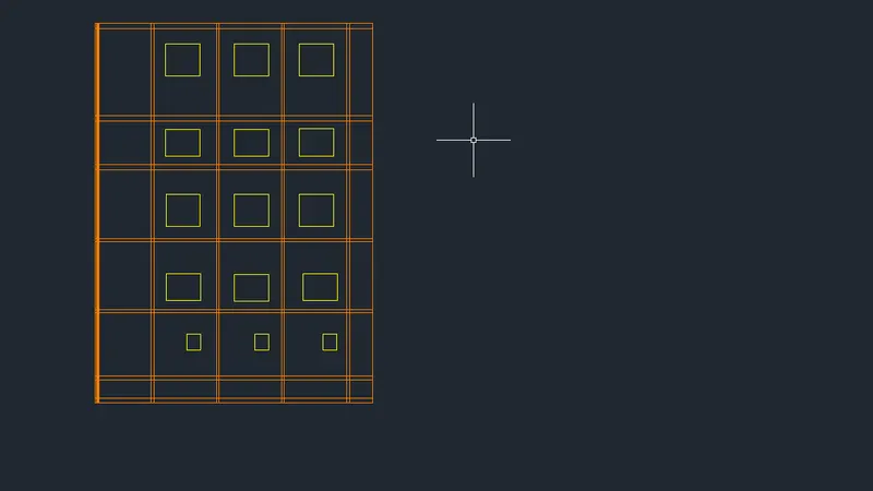
Using rectangle command draw a window with 1500X1400 as per W3 dimensions
Using rectangle command draw a window with 600X700 as per W4 dimensions
Copy the rectangles to all the floors as shown in figure
Trim off the outer extra potions and projection line of window
Using rectangle command draw beams of size 250X250 above all the walls
Draw the windows on the right wall in the plan according to step 4 window drawing method as shown in figure along with window shades
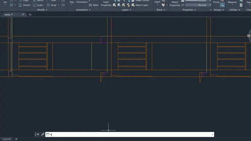
Type ‘o’ or offset and press enter or click offset from the modify tool bar
- Specify offset distance: Type 75 and press enter
- Select object to offset: Select the top edge and click on right
Trim off all the extra portions
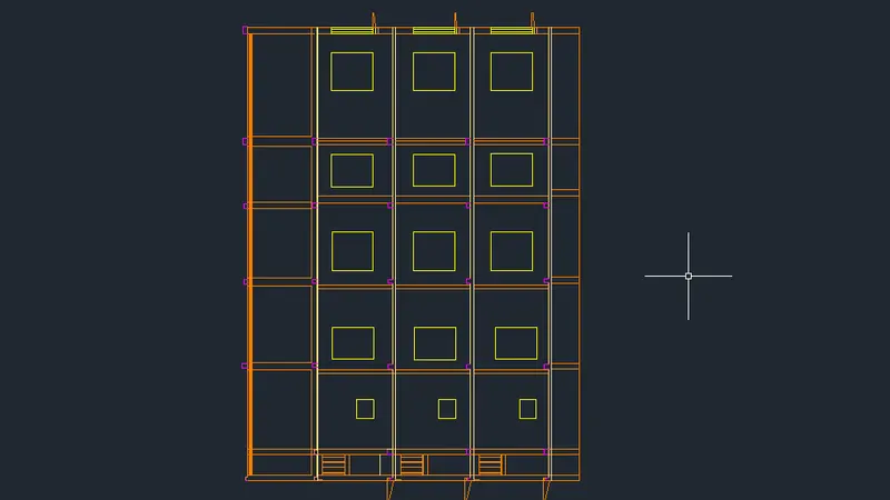
The final figure of section AA after assigning all the layers is as follows
Step 7: Adding text and dimensions
Text
Go to annotate tab and click on the arrow at the below to open the text properties
In the dialogue box click on new style
- Set style name to ‘New’
- Change Font Name to Berlin sans FB
- Change height to 200
- Click on set current and apply and close
Type ‘text’ in command box and press enter
- Specify start point of the text: Select inside the first box at the start point
- Specify rotation angle of text: Type 0o press enter
- Now the type 1ST, 2ND & 3RD Floor Plan in the first line and press esc
Follow the same procedure to all the horizontal text
Type ‘mtext’ in command box and press enter
- Specify start point of the text: Select inside the 3rd box at the start point
- Specify rotation angle of text: Type 90o press enter
- Now the type the BEDROOM press enter and type 3100X3100 and press esc
Follow the same procedure to all the multi text
Dimensions
- Dimlinear for linear dimnesion
- Dimcontinue for continue dimension for entire length
- Dimbreak for intersecting dimensions
- Mleader for adding floor layers specification
Result:
Floor plan of 1st, 2nd and 3rd floors with two section views from front side are drawn. Initially layers are created in step 1 to avoid confusion later. In the next step flat C and flat D are made as per dimensions from the plan. Then stairs are made with respective layers, where thread size is given as 250 and raiser as 143.75 for ground floor and 158.33 for rest of the floors. The dimensions and text are added according for plan after creating flats A and B. Section views are drawn from projection lines from the plan view. The result provided consists of pics dividing each drawing to parts if necessary.
- All the dimensions mentioned are in feet and inches
- Dimensions and text are assigned using dimension layer and text layers
- All components are assigned with respective layers and hatching is done for all columns and 75mm thick B.F.S.
- Floor Plan
- Section AA
3.Section BB.